Corona alternating current electrospinning: A combined approach for increasing the productivity of electrospinning
Farkas B., Balogh A., Cselko R., Molnár K., Farkas A., Borbas E., Marosi Gy., Nagy Z. K.
This accepted author manuscript is copyrighted and published by Elsevier. It is posted here by agreement between Elsevier and MTA. The definitive version of the text was subsequently published in [International Journal of Pharmaceutics, 561, 2019, DOI:
10.1016/j.ijpharm.2019.03.005]. Available under license CC-BY-NC-ND.
Powered by TCPDF (www.tcpdf.org)
1
Corona Alternating Current Electrospinning: A combined approach for
1
increasing the productivity of electrospinning
2
Balázs Farkasa, Attila Balogha,*, Richárd Cselkób, Kolos Molnárc,d, Attila Farkasa, Enikő 3
Borbása, György Marosia, Zsombor Kristóf Nagya 4
aBudapest University of Technology and Economics, Department of Organic Chemistry and 5
Technology, H-1111 Budapest, Hungary 6
bBudapest University of Technology and Economics, Department of Electric Power 7
Engineering, H-1111 Budapest, Hungary 8
cBudapest University of Technology and Economics, Department of Polymer Engineering, 9
H-1111 Budapest, Hungary 10
dMTA–BME Research Group for Composite Science and Technology, H-1111 Budapest, 11
Hungary 12
13
* Corresponding author at: Hungary, 1111 Budapest, Budafoki út 8. E-mail address:
14
baloghattila5@gmail.com (A. Balogh) 15
16
Keywords: corona electrospinning, polyvinylpyrrolidone, oral drug delivery, nanotechnology, 17
dissolution enhancement, solution conductivity, scale-up 18
Abstract 19
Corona alternating current electrospinning (C-ACES), a scaled-up productivity 20
electrospinning method was developed by combining the intense forces of the alternating 21
electrostatic field and a sharp-edged spinneret design with increased free surface. C-ACES 22
reached two orders of magnitude higher productivity (up to 1200 mL/h) than the classical single 23
needle direct current electrospinning (DCES) without any alteration of fiber properties.
24
Polyvinylpyrrolidone K90 (PVPK90), a water soluble high molecular weight nonionic polymer 25
2
was processed for the first time with single needle alternating current electrospinning (ACES) 26
and C-ACES in order to prepare fast dissolving amorphous solid dispersions of spironolactone 27
(SPIR), a poorly water-soluble antihypertensive model drug. The limited spinnability of 28
PVPK90 with AC high voltage could only be resolved by optimizing the solution conductivity 29
with organophilic salts such as sodium dodecyl sulfate (SDS) demonstrating the importance of 30
conductivity during ACES. The effects of varied solution properties (composition and 31
conductivity) and scaling-up were investigated by SEM imaging. Solid state analyses revealed 32
that SPIR was dispersed in an amorphous form in the fibrous mats. In vitro dissolution tests 33
showed ultrafast drug release in case of the amorphous formulations even when prepared with 34
scaled-up C-ACES. Besides the enhancement of conductivity SDS also prevents SPIR from 35
precipitation from the dissolution media due to its solubilization ability.
36
1. Introduction 37
The number of poorly water soluble drugs for the last decades has been growing in the 38
pharmaceutical industry. This phenomenon sets a great challenge for pharmaceutical 39
researchers since poor water solubility leads to low dissolution speed and therefore 40
unsatisfactory bioavailability levels. Therefore, the development of methods aiming to 41
overcome this hurdle is becoming more and more important (Kawabata et al., 2011, 42
Vasconcelos et al., 2007).
43 44
Dissolution properties can be enhanced by increasing the specific surface area and the 45
saturation solubility of the drug based on the Noyes-Whitney equation (Hörter and Dressman, 46
2001, Yu et al., 2018). For creating large surfaces particle size reduction methods such as 47
micronization and nanonization are applicable ways (Li et al., 2017). In addition, higher 48
dissolved drug concentration can be achieved by solubilizing the drug using surfactants or 49
complexing agents such as cyclodextrins (Borbás et al., 2015). Besides these approaches, the 50
3
amorphization of a drug by preparing amorphous solid dispersions (ASDs) allows much higher 51
drug concentration by reaching a supersaturated state (Yu et al., 2019, Zupančič et al., 2018a).
52
By forming a molecular dispersion of an active pharmaceutical ingredient (API) in a matrix 53
polymer, ASDs lead to an enhanced dissolution due to the higher energy state of the drug 54
amorphized this way (Škrlec et al., 2019). Moreover, it has been shown that not only the release 55
but the absorption is also assisted with ASDs due to the evolving supersaturated solution during 56
dissolution (Borbás et al., 2018, Frank et al., 2014). The number of marketed pharmaceutics 57
based on ASDs has almost doubled in the last five years indicating the importance of these 58
methods (Jermain et al., 2018).
59 60
The combination of the amorphous form of the API and increased specific surface area 61
results in even better dissolution. Electrospinning (ES) has gained great attention due to the 62
ability to form large surface area fibrous ASDs from polymeric solutions and melts under the 63
drawing force of the electrostatic field (Balogh et al., 2018, Balogh et al., 2014, Hirsch et al., 64
2018, Marosi et al., 2018, Zupančič et al., 2018b). Direct current electrospinning (DCES) is the 65
simplest and most common method for preparing electrospun ASDs with controlled drug 66
release (e.g., sustained (Angkawinitwong et al., 2017, Liu et al., 2018), targeted (Nagy et al., 67
2013) or ultrafast release (Farkas et al., 2018, Nagy et al., 2010)). Despite these advantages the 68
productivity of DCES is quite low (∼1–2 g/h) for industrial applications (Lukáš et al., 2009).
69
The simplest attempt for the scale up was the introduction of multiple spinnerets, although it 70
turned out to be challenging due to the perpetual clogging of the spinning tips (Theron et al., 71
2005). Therefore, needleless methods were developed to increase productivity such as free 72
surface ES (Persano et al., 2013). Even better results could be achieved with the combination 73
of the centrifugal force and the electrostatic field with a reported maximum of 1500 mL/h at 74
40,000 rpm (Kostakova et al., 2017, Nagy et al., 2015).
75
4 76
At corona ES the solution continuously exits a narrow, annular orifice (Molnar and 77
Nagy, 2016). The annulus is surrounded by a metal electrode having sharp edge from the 78
outside. The highest electrical charge density forms along the sharp edge (i.e., where the 79
solution is fed), which results in many Taylor-cones. The spinneret is rotated at moderate 80
angular velocity in order to homogeneously disperse the polymer solution along the annulus 81
and to prevent local overflows. Corona ES offers a much simpler mechanical design compared 82
to the high frequency versions and reaches a maximum productivity of 300 mL/h, thus, it could 83
offer a more desired choice for the scale up of electrospinning.
84 85
Novel alternating current electrospinning (ACES) also provides multiple times higher 86
productivities by simply replacing the direct current high voltage generator with an alternating 87
current power supply (Balogh et al., 2015a, Pokorny et al., 2014). During ACES multiple jets 88
are drawn from the droplet leaving the tip of the spinneret. As a result, a so-called nanofibrous 89
plume is generated from the polymeric solutions carried by the electric wind. Due to the 90
alternately charged plume the collection is implemented without a grounded surface making 91
the process simpler with similar fiber morphology compared to DCES. The productivity of 92
ACES could also be extended with the combination of the centrifugal force expecting even 93
higher throughputs compared to DC high voltage. However, ACES has never been connected 94
with a rotating-type spinneret so far.
95 96
Recent studies revealed that solution conductivity is an essential factor during ACES 97
besides the molecular weight of the applied polymer. Cellulose derivatives of low molecular 98
weight hydroxypropylmethylcellulose (HPMC 2910, Mw = 20 kDa) and 99
hydroxypropylmethylcellulose acetate succinate (HPMCAS LF, Mw = 18 kDa) were processed 100
5
with ACES for pharmaceutical uses (Balogh et al., 2017, Balogh et al., 2016). Both HPMC and 101
HPMCAS were found to be poorly electrospinnable regardless the type of the applied high 102
voltage. The addition of small amounts of polyethylene oxides as active fiber forming agents 103
resolved the issue of poor fibers with HPMC. In the case of HPMCAS the optimization of 104
solution conductivity was also required for defect-free AC electrospun fibers. For that purpose 105
SDS, NH4OAc and CaCl2 were suitable excipients and also well soluble in the used solvent 106
mixture (DCM-EtOH 1:1). A high molecular weight polymer never failing with DCES, 107
polyvinylpyrrolidone K90 (PVPK90) was also tested with ACES, but only low quality samples 108
could be obtained at higher feeding rates (Balogh et al., 2015a). Thus, the question arises 109
whether the optimization of solution conductivity would result in good quality fibrous mats 110
from PVPK90.
111 112
Accordingly, in this study we attempted to increase the productivity of ES with the 113
combination of ACES and the corona-type spinneret. Polyvinylpyrrolidone K90 (PVPK90) 114
was selected as fiber forming polymer considering that one third of the marketed ASDs are 115
based on polyvinylpyrrolidones. Relying on our earlier experiences the hurdle of poor ACES 116
electrospinnability of PVPK90 was attempted to be resolved by the optimization of solution 117
conductivity. Spironolactone (SPIR), an antihypertensive with limited water solubility 118
(28 µg/mL, (Nagy et al., 2012)) was chosen as the model drug. SPIR is known for being prone 119
to precipitation; this matter also had to be considered during formulation development. The 120
morphology of the fibrous samples was monitored with scanning electron microscopy (SEM).
121
The physical state of the drug was studied with differential scanning calorimetry (DSC), X- 122
ray powder diffraction (XRPD) and Raman mapping. In vitro dissolution tests were 123
6
performed in order to examine the characteristics of the drug release.
124
125
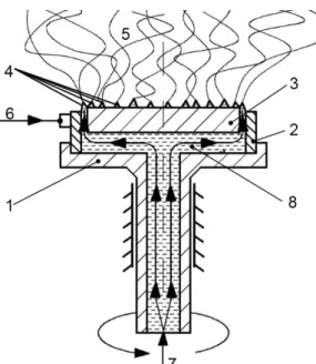
Figure 1. The corona electrospinning setup. 1) rotating spinneret, 2) high voltage 126
electrode, 3) inner part, 4) annular orifice with forming Taylor-cones, 5) forming fibers, 127
6) high voltage source, 7) solution feed, 8) distribution channel (Molnar et al. 2012) 128
129
2. Materials and methods 130
2.1. Materials 131
Polyvinylpyrrolidone K90 (PVPK90) with an average molecular weight of ∼1000 kDa was 132
received from BASF (Ludwigshafen, Germany). Spironolactone (SPIR) from Sigma-Aldrich 133
(Budapest, Hungary) was used as API. Organic and inorganic salts of sodium dodecyl sulfate 134
(SDS), anhydrous calcium chloride (CaCl2), and ammonium acetate (NH4OAc) were obtained 135
from Sigma-Aldrich. Absolute ethanol (EtOH) and dichloromethane (DCM) were purchased 136
from Molar Chemicals (Budapest, Hungary).Direct current electrospinning (DCES) 137
138
2.2. Direct current electrospinning (DCES) 139
The DCES tests were conducted using an NT-35 high voltage direct current supply 140
(MA2000; Unitronik Ltd, Nagykanizsa, Hungary). The electrical potential applied on the 141
7
spinneret electrode was 25 kV in all cases. A grounded aluminum plate covered with aluminum 142
foil was used as collector. The distance of the spinneret and the collector was 20 cm. Solutions 143
of the polymeric excipient and the drug were prepared for electrospinning using a magnetic 144
stirrer (600 rpm). The solutions were dosed by a SEP-10S Plus type syringe pump through a 145
needle spinneret (1 mm ID, 2 mm OD) at 10 mL/h rate.
146
2.3. Direct current corona electrospinning (C-DCES) 147
The C-DCES tests were conducted using an NT-35 high voltage direct current supply 148
(MA2000; Unitronik Ltd, Nagykanizsa, Hungary). The electrical potential applied on the 149
spinneret electrode was 40 kV in all cases. A grounded aluminum plate covered with aluminum 150
foil was used as collector. The distance of the spinneret and the collector was 20 cm. Solutions 151
of the polymeric excipient and the drug were prepared for electrospinning similarly to that of 152
the DCES experiments. The solutions were dosed by a SEP-10S Plus type syringe pump 153
through a corona spinneret (110 mm OD) at 100-300 mL/h rate.
154
2.4. Alternating current electrospinning (ACES) 155
The ACES experiments were conducted using an FME-24 voltage transformer 156
(24,000 V/100 V ratio) (Transzvill Ltd, Budapest, Hungary) fed by a 0–230 V variable 157
transformer. The electrical potential applied on the spinneret electrode was 25 kV (root mean 158
square, RMS) at the frequency of the mains voltage (50 Hz). The sinusoidal AC high voltage 159
was controlled by manual feedback using the variable transformer based on the measured output 160
signal of a high voltage probe connected to the electrode. Solutions of the polymeric excipient 161
and the drug were prepared for electrospinning using a magnetic stirrer (600 rpm). The solutions 162
were dosed by a Harvard Apparatus Model 33 type twin syringe pump (Harvard Apparatus Inc., 163
Holliston, Massachusetts, USA) through a needle spinneret (1 mm ID, 3 mm OD) at 164
predetermined flow rates. The flying fibers were collected in a basket fixed to an insulating 165
PVC rod positioned above the spinneret in 20–100 cm distances.
166
8
2.5. Corona alternating current electrospinning (C-ACES) 167
The corona alternating current electrospinning (C-ACES) experiments were performed 168
with a rotating corona spinneret set to 100 rpm ((Molnar and Nagy, 2016), Fig. 4). The diameter 169
of the annular orifice was 110 mm. The annulus was surrounded by a sharp-edged aluminum 170
part from the outside and a polyamide part from the inside. The gap size (gap between these 171
two parts, in which the solution leaves the spinneret) was 1 mm. The C-ACES experiments 172
were conducted using a TUR PEO 8/100A voltage transformer (200/100,000 V ratio, VEB 173
Transformatoren und Röntgenwerk Dresden) fed by a 0–230 V variable transformer. The 174
electrical potential applied on the corona spinneret electrode was 100 kV (root mean square, 175
RMS) at the frequency of the mains voltage (50 Hz). The sinusoidal AC high voltage was 176
controlled by manual feedback using the variable transformer based on the measured output 177
signal of a high voltage capacitive divider connected to the electrode. Polymeric solutions were 178
prepared similarly to the ACES experiments, and the same Harvard Apparatus Model 33 type 179
twin syringe pump was used for feeding the corona spinneret between 100 and 1500 mL/h rate.
180
For safety precautions, both the syringe pump and the corona spinneret were operated from a 181
12 V battery and placed in a Faraday-cage. The collection of the fibers was aided with a 182
grounded metal grid positioned 75 cm above the rotating spinneret.
183
2.6. Scanning electron microscopy (SEM) and fiber diameter analysis 184
Morphology of the samples was investigated by a JEOL 6380LVa (JEOL, Tokyo, 185
Japan) type scanning electron microscope. Each specimen was fixed by conductive double- 186
sided carbon adhesive tape and sputter coated with gold prior to the examination. Applied 187
accelerating voltage and working distance were 15–30 kV and 10 mm, respectively. A 188
randomized fiber diameter determination method was used based on scanning electron 189
microscopy imaging as described in our previous work (Balogh et al., 2015b), n = 100 190
measurements were made on each sample.
191
9 2.7. Differential scanning calorimetry (DSC) 192
Differential scanning calorimetry measurements were carried out using a Setaram 193
(Calure, France) DSC 92 apparatus (sample weight: ∼10–15 mg, open aluminum pan, nitrogen 194
flush). The temperature program consisted of an isothermal period, which lasted for 1 min at 195
25 °C, with subsequent linear heating from 25 °C to 250 °C at the rate of 10 °C/min. Purified 196
indium standard was used to calibrate the instrument.
197
2.8. X-ray powder diffraction (XRPD) 198
Powder X-ray diffraction patterns were recorded by a PANanalytical X’pert Pro MDP 199
X-ray diffractometer (Almelo, The Netherlands) using Cu-Kα radiation (1.542 Å) and Ni filter.
200
The applied voltage was 40 kV while the current was 30 mA. The untreated materials, a physical 201
mixture composition and the fibrous samples as spun were analyzed for angles 2θ between 4°
202
and 42°.
203
2.9. Raman mapping 204
Raman mapping was carried out using a Horiba Jobin–Yvon LabRAM (Longjumeau, 205
France) system coupled with an external diode laser source (785 nm, 80 mW) and an Olympus 206
BX-40 optical microscope. The fibrous samples were gently compressed into a flat tablet 207
(Camilla OL95; Manfredi, Torino, Italy) and the spectra were recorded with an objective of 208
50× (NA = 0.5) magnification. The measured area was 100 × 100 µm2 with 5 µm step size in 209
both directions meaning that 441 spectra were gathered from each sample. The component 210
concentrations were estimated with the classical least squares (CLS) method using the reference 211
spectra of the pure components collected on the same device under the same conditions.
212
Visualized score maps were created with LabSpec 5.41 (Horiba Jobin–Yvon).
213
2.10. In vitro dissolution measurement 214
The dissolution studies were performed using a Pharmatest PTWS 600 dissolution tester 215
(USP II apparatus (paddle); Hainburg, Germany). Samples equivalent to 25 mg of SPIR were 216
10
added directly into the dissolution vessel containing 900 mL of dissolution liquid (pH = 6.8 217
100 mM phosphate buffer prepared according to USP). Electrospun samples were used for 218
dissolution tests as spun. The temperature was maintained at 37 ± 0.5 °C and stirred at 100 rpm.
219
An on-line coupled Agilent 8453 UV–Vis spectrophotometer (Palo Alto, CA) was used to 220
measure the concentration of dissolved SPIR at a wavelength of 244 nm. Percentage of 221
dissolution was readily calculated according to the calibration curve of SPIR due to the lack of 222
absorption peaks of the applied excipients in this range.
223 224
3. Results and discussion 225
3.1.Processing PVPK90 with ACES 226
PVPK90 is known to be well processable with DCES. It was no different in this case since fine PVPK90 227
fibers could be electrospun from simple DCM-EtOH solutions at a throughput rate of 10 mL/h utmost. In 228
contrast as described in the introductory part PVPK90 could not be processed with ACES at increased 229
throughput rates (>10 mL/h) during an earlier study from simple ethanol-based solutions (Balogh et al., 230
2015a). To begin with, the optimization of polymer concentration and conductivity was performed in order 231
to obtain AC electrospun PVPK90 nanofibers at elevated productivity. A 42 full factorial design of 232
experiments (DoE) was carried out, the amount of PVPK90 and the solution conductivity were set on four 233
levels (see Table 1 for exact values). SDS was selected to adjust conductivity as an organic salt well soluble 234
in DCM-EtOH solvent mixtures. The concentration of SDS was exponentially increased so that its effect on 235
fiber morphology could be investigated in a wider range. The concentration of PVPK90 was varied based 236
on earlier experiments with pure ethanol (Balogh et al., 2015a, Vigh et al., 2013). The mixture of DCM- 237
EtOH (50:50 vol/vol%) was used as it is able to dissolve both hydrophobic and hydrophilic components 238
while high volatility aids fiber formation and minimizes residual solvent content.
239
Table 1. The 42 design table for solution compositions tested with ACES of PVPK90. The optimal 240
composition is marked with green.
241
PVPK90-SDS compositions dissolved in 10 mL pure DCM-EtOH 1:1
PVPK90 SDS and solution conductivity
7,5 mg (~34 µS/cm) 15 mg (~52 µS/cm) 30 mg (~75 µS/cm) 60 mg (~103 µS/cm) 250 mg Mainly beads and
droplets, few fibers
Mainly beads and droplets, few fibers
Mainly beads and droplets, few fibers
Mainly beads and droplets, few fibers
11
Fig. 2a 500 mg Beads and droplets,
more fibers
Beads and droplets, more fibers
Beads and droplets, more fibers
Fig. 2b
Beads and droplets, more fibers 750 mg
Less beads and droplets, more fibers
Fig. 2e
Less beads and droplets, more fibers
Fig. 2f
No beads, no droplets, decent fibers
Fig. 2c
More beads and droplets, poor fibers
Fig. 2 g 1,000 mg More beads and
droplets, poor fibers
More beads and droplets, poor fibers
More beads and droplets, poor fibers
Fig. 2d
More beads and droplets, poor fibers As it can be seen in Fig. 1, SDS is an effective conductivity enhancer since a 7-fold increase in 242
solution conductivity could be observed even when added in low concentrations (∼34 µS/cm 243
in the 7.5 mg/10 mL solution compared to the initial solution with no SDS (∼5 µS/cm)).
244
Concentrations over 60 mg/10 mL resulted in regressively increasing conductivity thereby also 245
approaching the solubility limit of SDS. This range of conductivity proved to be feasible during 246
earlier studies to examine the effect of solution conductivity on fiber morphology in case of 247
ACES (Balogh et al., 2017).
248
249
Figure 1. Conductivity as a function of dissolved SDS in 10 mL DCM-EtOH 1:1. The value of conductivity 250
was found to be independent from the concentration of dissolved PVPK90.
251
12 252
Figure 2. Scanning electron microscopic images of AC electrospun PVPK90 fibers as a function of (a-d) 253
polymer concentration at fixed conductivity (optimal 75 µS/cm) and (e-h) SDS concentration at fixed 254
polymer concentration (optimal 750 mg/10 mL pure solvent). Images c and g show the same overall 255
optimum. (DCM-EtOH 1:1, 25 kVRMS, 60 mL/h) 256
257
The DoE study provided the following results: Beads and droplets appeared among the fibers 258
spun at low polymer concentrations (250 mg or 500 mg PVPK90 in 10 mL DCM-EtOH 1:1) 259
regardless the applied amount of SDS (Fig. 2a and b). However, with an increased conductivity 260
the amount of beads and droplets notably reduced. Increasing the concentration of PVPK90 to 261
750 mg/10 mL and setting SDS to 30 mg/10 mL (∼75 µS/cm) resulted in bead- and droplet- 262
free, excellent quality fibers (Fig. 2c and g) giving the optimal composition.
263
264
13
Figure 3. Comparison of AC electrospun PVPK90 samples (a) without SDS added in the solution and (b) 265
with SDS introduced in the solution (25 kVRMS, 60 mL/h).
266
The remarkable difference between the AC electrospun PVPK90 samples without and 267
with adjusting conductivity can be seen in Fig. 3. Without adding SDS into the polymer solution 268
the ACES resulted in the spattering of the liquid with little amount of fibers formed making the 269
product practically non collectible (Fig. 3a). In comparison a loose, easily collectible fibrous 270
plume could be obtained when the solution conductivity was optimized with SDS (Fig. 3b).
271
That result provided satisfactory evidence to our primary hypothesis that the processability of 272
PVPK90 with ACES can be resolved simply with optimized conductivity and without the need 273
for other polymeric excipients such as PEO.
274
The determined optimal conductivity value (∼75 µS/cm) resembles with our earlier 275
findings with HPMCAS solutions indicating a more general correlation between solution 276
conductivity and AC electrospinnability (Balogh et al., 2017). Presumably, ionic additives aid 277
faster charge transfer rates when polarity changes periodically on the polymeric liquid, thus, at 278
an optimum conductivity value the full potential of ACES can be reached in terms of defect- 279
free fiber morphology and increased throughput rates. When either the polymer concentration 280
or the conductivity was increased any further from the optimum values the quality decreased as 281
it can be seen in Fig. 2d and h. Adding the components over their optimum values larger droplets 282
appeared and the fibers thickened (Fig. 2h). It could be also observed that the fibrous samples 283
had become more brittle due to the contaminating particles with larger dimensions.Scaled up 284
productivity C-ACES experiments 285
14 286
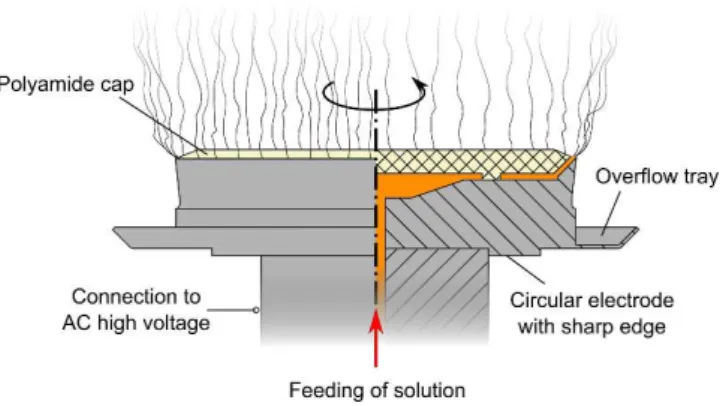
Figure 4. The schematic drawing of the C-ACES method with the corona spinneret (OD=110 mm) coupled 287
with AC high voltage. The application of a grounded surface is also recommended for proper fiber 288
formation (not shown here).
289
After the optimization of the production of PVPK90 with ACES, scaled-up preparation of 290
fibrous mats was attempted with C-DCES and the novel C-ACES method (Fig. 4). According 291
to previous studies the application of a corona spinneret usually requires higher DC voltage 292
(∼40 kV) compared to a single needle spinneret (25 kV) (Molnar and Nagy, 2016). C-DCES 293
could be operated at ten times higher throughput rate when processing the optimized PVPK90- 294
SDS solution compared to single needle DCES without any alteration in fiber morphology (Fig.
295
5a). However, the increase of feeding rate to 300 mL/h resulted in significantly deteriorated 296
fiber morphology with large droplets among the fibers (Fig. 5b). Also at this throughput range 297
a part of the solution sputtered and drained into the overflow tray of the corona plate indicating 298
that the maximum productivity in this case is around 100 mL/h.
299
300
15
Figure 5. SEM images of C-DCES placebo fibers prepared at (a) 100 mL/h and (b) 300 mL/h (25 kV).
301
For C-ACES a higher AC voltage of at least 75 kVRMS was needed to promote fiber production.
302
In comparison, the single needle ACES method only requires high voltages above 10 kVRMS. 303
Another notable aspect of using the corona spinneret with AC high voltage was the application 304
of a grounded surface in front of the spinneret to aid fiber formation. While ACES with a 305
needle- or rod-type spinneret operates readily without a grounded counterpole (known as 306
collectorless operation), during C-ACES without the grounded surface the fibrous plume was 307
flying too slowly and the fibers started to soak and stick to the cap of the spinneret.
308
The C-ACES experiments were executed at throughput rates gradually increased from 309
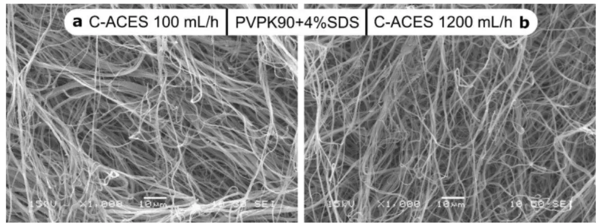
100 mL/h to 1200 mL/h by 100 units (Fig. 6). In the mentioned throughput range smooth fiber 310
formation could be observed. When increasing the flow rate to 600 mL/h (Fig. 6b) and further 311
to 1200 mL/h (Fig. 6c), the fibrous plume expanded and the formation of fibers became more 312
intense. Over 1200 mL/h the fibers started to get wet on the collector and the excess solution 313
spattered out of the plate of the spinneret. SEM revealed same C-ACES fiber quality as in case 314
of ACES since no droplets or bead-on-string structures were observable in the images (Fig. 2c 315
and Fig. 7). Increasing the high voltage over 100 kVRMS did not result in any significant 316
improvement in either fiber quality or productivity. C-ACES comes close to the most 317
productive yet simple ES method with a 20-fold throughput increase compared to single needle 318
16
ACES (60 mL/h) and with two orders of magnitude higher productivity compared to single 319
needle DCES (∼10 mL/h).
320
321
Figure 6. Production of PVPK90 fibers with C-ACES at (a) 100 mL/h, (b) 600 mL/h and (c) 1,200 mL/h (100 322
kVRMS, 75 cm spinneret-collector distance). 1 – Corona spinneret (110 mm OD); 2 – Fibrous plume 323
(highlighted); 3 – Grounded grid; 4 – Measuring capacitor; 5 – High voltage power supply.
324
325
Figure 7. SEM images of C-ACES placebo fibers prepared at (a) 100 mL/h and (b) 1,200 mL/h feeding rates 326
(100 kVRMS).
327
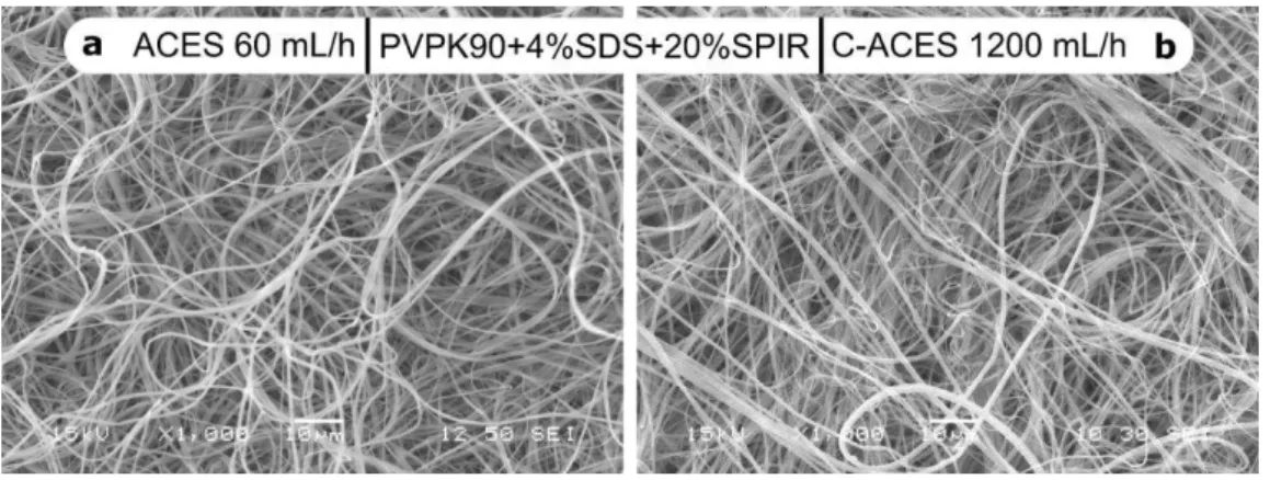
3.2.Preparing drug-loaded scaled up productivity C-ACES fibers 328
After the optimization of the composition, drug-loaded PVPK90 fibers with 20% SPIR content 329
(w/w) were attempted to prepare using these methods in order to enhance the dissolution 330
properties of SPIR. The high throughput rate of C-ACES could be maintained even in the 331
presence of the active substance. As it can be seen in Fig. 8, excellent quality drug-loaded 332
17
PVPK90-SDS-SPIR fibers could be obtained with both ACES and C-ACES possessing large 333
surfaces thereby an enhanced drug dissolution is expected.
334
335
Figure 8. PVPK90-based nanofibers with SPIR content prepared with (a) ACES (60 mL/h) and (b) C-ACES 336
(1,200 mL/h).
337
3.3.Fiber diameter analysis 338
Fiber diameter analysis was carried out in order to investigate the effects of the preparation 339
methods and drug loading on fiber thickness. Table 2 shows that the average diameters of the 340
placebo PVPK90 + 4%SDS fibers are similarly around 1 µm regardless the type of high voltage 341
or the spinneret used. The results with PVPK90 fibers without any other components show 342
negligible effect of SDS on the average fiber diameter. The multiple times higher throughput 343
of C-ACES and C-DCES did not result in thicker fibers either. In case of the AC electrospun 344
fibers with SDS and 20% SPIR content, the average diameter is about 20% thinner than that of 345
the placebo samples. This fiber thinning phenomenon has already occurred in previous cases 346
when SPIR was applied as active compound (Balogh et al., 2017, Balogh et al., 2016). A 347
different conclusion could be drawn when SDS was replaced to CaCl2 and NH4OAc in ACES 348
fibers (see more in Section 3.6), in these cases the SPIR-loaded PVPK90 samples occurred to 349
be thicker than the placebo fibers if they contained NH4OAc or CaCl2 (Fig. 9). Thus, further 350
18
investigation is needed to fully explain the dependence of AC electrospun fiber diameter on the 351
composition of the polymer solution.
352
Table 2. Mean fiber diameters of DC (10 mL/h, 25 kV), C-DC (100 mL/h, 40 kV), AC (60 mL/h, 25 kVRMS) 353
and C-AC (1,200 mL/h, 100 kVRMS) electrospun PVPK90-based fibers with optimized amounts of salts (SDS, 354
CaCl2, NH4OAc) with and without SPIR.
355
Composition Mean fiber diameter (µm± SD) DCES
(10 mL/h)
C-DCES (100 mL/h)
ACES (60mL/h)
C-ACES (1,200 mL/h)
PVPK90 0.88±0.27 0.92±0.27 poor fibers poor fibers
PVPK90+4%SDS 0.93±0.35 0.87±0,39 1.14±0.46 1.07±0.55
PVPK90+4%SDS+20%SPIR - - 0.83±0.35 0.81±0.32
PVPK90+2.5%NH4OAc - - 0.72±0.22 -
PVPK90+2.5%NH4OAc+20%SPIR - - 1.07±0.45 -
PVPK90+0.5%CaCl2 - - 1.00±0.59 -
PVPK90+0.5%CaCl2+20%SPIR - - 1.67±0.69 -
3.4.Physical characterization of the electrospun samples 356
357
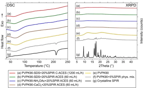
Figure 9. Differential scanning calorimetry thermograms (DSC) and X-ray powder diffraction patterns 358
(XRPD) of (a-d) AC and C-AC electrospun PVPK90-based SPIR-loaded nanofibers, (e) PVPK90, 359
(f) physical mixture of PVPK90 and 5% SPIR and (g) crystalline SPIR.
360 361
3.5. Physical characterization 362
19
In order to investigate the physical state of SPIR in the drug-loaded electrospun formulations 363
DSC measurements were carried out first (Fig. 10). The melting peak of the crystalline drug is 364
well observable around 210 °C in the curve of the pure crystalline SPIR and the 5% physical 365
mixture as well (Fig. 10f and g). In the cases of the drug-loaded electrospun samples no such 366
signs were detected suggesting the amorphization of SPIR, only the endothermic water loss of 367
PVPK90 can be seen between 50 °C and 100 °C (Fig. 10a–e). These results also confirm the 368
smooth operation of C-ACES regardless the much higher throughput rate applied compared to 369
ACES and conventional DCES.Additional measurements were recorded with XRPD, another 370
delicate method for identifying small traces of crystallinity. The sharp peaks of crystalline SPIR 371
is clearly visible, the most intense ones are at 8° and between 16° and 18° (Fig. 9f-g). PVPK90 372
as well as the drug-loaded samples were found to be amorphous. Thus, based on both the DSC 373
and XRPD measurements SPIR was dispersed in a fully amorphous form in the electrospun 374
formulations owing mainly to the fast drying effect of C-ACES and ACES.
375
20 376
Figure 10. Raman maps illustrating the distribution of SPIR in (a) PVPK90-crystalline SPIR reference and 377
(b) drug-loaded C-ACES fibers (1,200 mL/h, 100kVRMS). Calculated SPIR content is illustrated by different 378
colors in the maps from 0.0 (0%) to 1.0 (100%).
379
Additional measurements were recorded with XRPD, another delicate method for identifying 380
small traces of crystallinity. The sharp peaks of crystalline SPIR is clearly visible, the most 381
intense ones are at 8° and between 16° and 18° (Fig. 10f and g). PVPK90 as well as the drug- 382
loaded samples were found to be amorphous. Thus, based on both the DSC and XRPD 383
measurements SPIR was dispersed in a fully amorphous form in the electrospun formulations 384
owing mainly to the fast drying effect of C-ACES and ACES.
385
386
21
Raman mapping analyses were carried out in order to demonstrate the homogeneity of the drug 387
in the fibrous sample produced by C-ACES at high feeding rate (1200 mL/h). Raman 388
microspectroscopy is also an excellent method for identifying small traces of crystalline SPIR 389
because specific peaks of the crystalline and amorphous API distinctly differ (Patyi et al., 2010).
390
A casted PVPK90 + 20%SPIR film served as reference containing drug crystals since SPIR 391
tends to crystallize when the evaporation of the solvent is too slow. In Fig. 11a the 392
inhomogeneous distribution of SPIR is well observable in the casted film reference. The 393
brighter areas on the map represent nearly 100% SPIR content where the specific peak of 394
crystalline SPIR at 1690 cm−1 appeared in the Raman spectra. In contrast, all the drug-loaded 395
electrospun samples showed homogeneous distribution of SPIR based on the Raman results 396
(Fig. 11b). The merging of the peak at 1690 cm−1 with the adjacent peak signifies amorphous 397
SPIR content in the samples. To sum it up, Raman mapping revealed homogenous distribution 398
and amorphous SPIR content in the drug-loaded fibers in good accordance with the DSC and 399
XRPD measurements (Fig. 12).
400
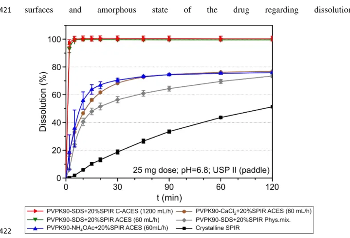
In vitro dissolution tests 401
In order to explore the drug release from the electrospun samples in vitro dissolution tests were 402
carried out. Only half of the 25 mg dose dissolved from the crystalline SPIR reference after two 403
hours indicating limited solubility. All the electrospun fibers showed enhanced drug release, in 404
the case of the electrospun fibers with SDS the release was complete within 5 min. The ACES 405
and C-ACES samples exhibited equally fast dissolution.
406
Further fibrous samples were prepared and tested to examine the importance of SDS during the 407
enhanced dissolution of SPIR. When SDS was replaced with NH4OAc or CaCl2 in the AC 408
electrospun fibers for conductivity adjustment, SPIR concentration slowly peaked at 75% after 409
90 min. This phenomenon is similar to what Vigh et al. experienced with amorphous SPIR- 410
loaded PVP webs (Vigh et al., 2013). Accordingly, SPIR immediately crystallizes from PVP 411
22
formulations in the absence of a surfactant or complexing agent due to temporary gelation and 412
therefore induced hindered drug diffusion. Thus, besides determining conductivity, SDS also 413
prevents SPIR from precipitation during dissolution.
414
Based on these findings regarding the role of SDS one could wonder whether the fast drug 415
release of SPIR can be attributed only to the solubilizing effect and the huge surface area and 416
the amorphous form are less important. Therefore, the dissolution of the physical mixture of 417
the optimal composition used in the ACES and C-ACES experiments 418
(PVPK90 + 4%SDS + 20%SPIR) was also measured. In this case the dissolution reached again 419
only 75% after two hours in spite of the applied SDS. This verifies the importance of large 420
surfaces and amorphous state of the drug regarding dissolution.
421
422
Figure 11. Dissolution profiles of SPIR from drug-loaded, PVPK90-based AC electrospun fibers (as spun) 423
containing 20%SPIR. The error bars indicate the standard deviations (n = 3) [25 mg dose, 900 mL pH = 6.8 424
100 mM phosphate buffer, USP Dissolution Apparatus 2 (paddle), 100 rpm, 37°C].
425 426
23 4. Conclusion
427
The poor processability of PVPK90 with ACES was addressed via a thorough 428
optimization of conductivity and polymer concentration of the spinning solution. Similarly to 429
our earlier findings conductivity was found to be an important factor for ACES in the case of 430
PVPK90. As a result, excellent quality fibrous material could be AC electrospun with 431
submicronic diameters. With the optimized composition an attempt was made to scale up 432
electrospinning. By replacing the needle to a 110 mm rotating corona spinneret C-ACES was 433
able to achieve two orders of magnitude higher productivity compared to single needle DCES 434
and a 10-fold and a 20-fold increase compared to C-DCES and ACES, respectively. Drug- 435
loaded fibers were also successfully prepared with C-ACES at scaled-up productivity 436
maintaining similar fiber morphology to that of DCES and ACES. The physical state of the 437
drug was investigated with DSC and XRPD, SPIR was dispersed in an amorphous state in the 438
PVPK90 matrix in all the drug-loaded fibrous formulations. Raman mapping revealed that SPIR 439
was embedded homogenously in the fibrous samples, no traces of crystallinity could be detected 440
either. Based on fiber diameter analysis no difference could be observed between ACES and C- 441
ACES reference fibers despite the several times higher throughput of the corona spinneret.
442
When SPIR was added together with SDS the reduction of fiber diameter could be observed. In 443
turn, applying CaCl2 or NH4OAc with SPIR resulted in the thickening of the fibers compared 444
to the reference samples. In vitro dissolution studies showed ultrafast drug release in the case 445
of PVPK90-SDS-SPIR ACES and C-ACES samples. A suspected precipitation occurred with 446
CaCl2 and NH4OAc-loaded samples. These results indicate a double role of SDS: it increases 447
the conductivity of the electrospinning solution and hinders the precipitation of SPIR in the 448
dissolution media due to its solubilization ability. In summary, a new method was constructed 449
for a two orders of magnitude scale-up of conventional electrospinning with C-ACES also 450
capable to produce fibrous drug-loaded ASDs.
451
24 5. Acknowledgements
452
This work was supported by the National Research Development and Innovation in the frame 453
of FIEK_16-1-2016-0007 (Higher Education and Industrial Cooperation Center) project.
454
Supported by OTKA 121051, ÚNKP-18-3, ÚNKP-18-4-BME-95. New National Excellence 455
Program of the Ministry of Human Capacities and the János Bolyai Research Scholarship of 456
the Hungarian Academy of Sciences. Supported by Gedeon Richter’s Talentum Foundation.
457
References 458
Angkawinitwong, U., Awwad, S., Khaw, P.T., Brocchini, S., Williams, G.R., 2017. Electrospun 459
formulations of bevacizumab for sustained release in the eye. Acta Biomater. 64, 126–136.
460
https://doi.org/10.1016/j.actbio.2017.10.015 461
Balogh, A., Cselkó, R., Démuth, B., Verreck, G., Mensch, J., 2015a. Alternating current 462
electrospinning for preparation of fibrous drug delivery systems. Int. J. Pharm. 495, 75– 463
80. https://doi.org/10.1016/j.ijpharm.2015.08.069 464
Balogh, A., Domokos, A., Farkas, B., Farkas, A., Rapi, Z., Kiss, D., Nyiri, Z., Eke, Z., Szarka, 465
G., Örkényi, R., Mátravölgyi, B., Faigl, F., Marosi, G., Nagy, Z.K., 2018. Continuous end- 466
to-end production of solid drug dosage forms: Coupling flow synthesis and formulation 467
by electrospinning. Chem. Eng. J. 350, 290–299. https://doi.org/10.1016/j.cej.2018.05.188 468
Balogh, A., Drávavölgyi, G., Faragó, K., Farkas, A., Vigh, T., Sóti, P.L., Wagner, I., Madarász, 469
J., Pataki, H., Marosi, G., Nagy, Z.K., 2014. Plasticized drug-loaded melt electrospun 470
polymer mats: Characterization, thermal degradation, and release kinetics. J. Pharm. Sci.
471
103, 1278–1287. https://doi.org/10.1002/jps.23904 472
Balogh, A., Farkas, B., Faragó, K., Farkas, A., Wagner, I., Van Assche, I., Verreck, G., Nagy, 473
Z.K., Marosi, G., 2015b. Melt-blown and electrospun drug-loaded polymer fiber mats for 474
dissolution enhancement: A comparative study. J. Pharm. Sci. 104, 1767–1776.
475
25 https://doi.org/10.1002/jps.24399
476
Balogh, A., Farkas, B., Pálvölgyi, Á., Domokos, A., Démuth, B., Marosi, G., Nagy, Z.K., 2017.
477
Novel alternating current electrospinning of hydroxypropylmethylcellulose acetate 478
succinate (HPMCAS) nanofibers for dissolution enhancement : The importance of 479
solution conductivity. J. Pharm. Sci. 106, 1634–1643.
480
https://doi.org/10.1016/j.xphs.2017.02.021 481
Balogh, A., Farkas, B., Verreck, G., Mensch, J., Borbás, E., Nagy, B., Marosi, G., Nagy, Z.K., 482
2016. AC and DC electrospinning of hydroxypropylmethylcellulose with polyethylene 483
oxides as secondary polymer for improved drug dissolution. Int. J. Pharm.
484
https://doi.org/10.1016/j.ijpharm.2016.03.024 485
Borbás, E., Balogh, A., Bocz, K., Müller, J., Kiserdei, É., Vigh, T., Sinkó, B., Marosi, A., 486
Halász, A., Dohányos, Z., Szente, L., Balogh, G.T., Nagy, Z.K., 2015. In vitro dissolution- 487
permeation evaluation of an electrospun cyclodextrin-based formulation of aripiprazole 488
using μFluxTM. Int. J. Pharm. 491, 180–189. https://doi.org/10.1016/j.ijpharm.2015.06.019 489
Borbás, E., Nagy, Z.K., Nagy, B., Balogh, A., Farkas, B., Tsinman, O., Tsinman, K., Sinkó, B., 490
2018. The effect of formulation additives on in vitro dissolution-absorption profile and in 491
vivo bioavailability of telmisartan from brand and generic formulations. Eur. J. Pharm.
492
Sci. 114, 310–317. https://doi.org/10.1016/j.ejps.2017.12.029 493
Farkas, B., Balogh, A., Farkas, A., Domokos, A., Borbás, E., Marosi, G., Nagy, Z.K., 2018.
494
Medicated straws based on electrospun solid dispersions. Period. Polytech. Chem. Eng.
495
62, 310–316. https://doi.org/10.3311/PPch.11931 496
Frank, K.J., Westedt, U., Rosenblatt, K.M., Hölig, P., Rosenberg, J., Mägerlein, M., Fricker, 497
G., Brandl, M., 2014. What is the mechanism behind increased permeation rate of a poorly 498
soluble drug from aqueous dispersions of an amorphous solid dispersion? J. Pharm. Sci.
499
26
103, 1779–1786. https://doi.org/10.1002/jps.23979 500
Hirsch, E., Nacsa, M., Ender, F., Mohai, M., Nagy, Z.K., Marosi, G.J., 2018. Preparation and 501
Characterization of Biocompatible Electrospun Nanofiber Scaffolds. Period. Polytech.
502
Chem. Eng. 62, 1–9. https://doi.org/10.3311/PPch.12854 503
Hörter, D., Dressman, J.B., 2001. Influence of physicochemical properties on dissolution of 504
drugs in the gastrointestinal tract. Adv. Drug Deliv. Rev. 46, 75–87.
505
https://doi.org/10.1016/S0169-409X(00)00130-7 506
Jermain, S. V, Brough, C., Williams, R.O., 2018. Amorphous solid dispersions and nanocrystal 507
technologies for poorly water- soluble drug delivery - An update. Int. J. Pharm. 535, 379– 508
392. https://doi.org/10.1016/j.ijpharm.2017.10.051 509
Kawabata, Y., Wada, K., Nakatani, M., Yamada, S., Onoue, S., 2011. Formulation design for 510
poorly water-soluble drugs based on biopharmaceutics classification system: Basic 511
approaches and practical applications. Int. J. Pharm. 420, 1–10.
512
https://doi.org/10.1016/j.ijpharm.2011.08.032 513
Kostakova, E.K., Meszaros, L., Maskova, G., Blazkova, L., Turcsan, T., Lukas, D., 2017.
514
Crystallinity of Electrospun and Centrifugal Spun Polycaprolactone Fibers: A 515
Comparative Study. J. Nanomater. 2017, 1–9. https://doi.org/10.1155/2017/8952390 516
Li, H., Zhang, L.-L., Zhang, Y.Y., Yu, D.-G., 2017. Core-shell medicated nanoparticles 517
prepared using coaxial electrospray for fast dissolution of paracetamol. J. Investig. Med.
518
65, A2. https://doi.org/10.1136/jim-2017-MEBabstracts.5 519
Liu, Z.P., Zhang, Y.Y., Yu, D.-G., Wu, D., Li, H.L., 2018. Fabrication of sustained-release zein 520
nanoparticles via modified coaxial electrospraying. Chem. Eng. J. 334, 807–816.
521
https://doi.org/10.1016/j.cej.2017.10.098 522
27
Lukáš, D., Sarkar, A., Martinová, L., Vodsed’álková, K., Lubasová, D., Chaloupek, J., Pokorný, 523
P., Mikeš, P., Chvojka, J., Komárek, M., 2009. Physical principles of electrospinning 524
(electrospinning as a nano-scale technology of the twenty-first century). Text. Prog. 41, 525
59–140. https://doi.org/10.1080/00405160902904641 526
Marosi, G., Hirsch, E., Bocz, K., Toldy, A., Szolnoki, B., Bodzay, B., Csontos, I., Farkas, A., 527
Balogh, A., Démuth, B., Nagy, Z.K., Pataki, H., 2018. Pharmaceutical and 528
Macromolecular Technologies in the Spirit of Industry 4.0 62, 457–466.
529
https://doi.org/10.3311/PPch.12870 530
Molnár K., Nagy Zs.K., Marosi Gy, Mészáros L. Electrospinning spinneret and modified 531
electrospinning method for producing nanofibers in productive ways. Hungarian patent 532
P1200677 Budapest, Hungary (2012).
533
Molnar, K., Nagy, Z.K., 2016. Corona-electrospinning: Needleless method for high-throughput 534
continuous nanofiber production. Eur. Polym. J. 74, 279–286.
535
https://doi.org/10.1016/j.eurpolymj.2015.11.028 536
Nagy, Z.K., Balogh, A., Démuth, B., Pataki, H., Vigh, T., Szabó, B., Molnár, K., Schmidt, B.T., 537
Horák, P., Marosi, G., Verreck, G., Assche, I. Van, Brewster, M.E., 2015. High speed 538
electrospinning for scaled-up production of amorphous solid dispersion of itraconazole.
539
Int. J. Pharm. 480, 137–142. https://doi.org/10.1016/j.ijpharm.2015.01.025 540
Nagy, Z.K., Balogh, A., Drávavölgyi, G., Ferguson, J., Pataki, H., Vajna, B., Marosi, G., 2013.
541
Solvent-free melt electrospinning for preparation of fast dissolving drug delivery system 542
and comparison with solvent-based electrospun and melt extruded systems. J. Pharm. Sci.
543
102, 508–517. https://doi.org/10.1002/jps.23374 544
Nagy, Z.K., Balogh, A., Vajna, B., Farkas, A., Patyi, G., Kramarics, Á., György, M., 2012.
545
Comparison of electrospun and extruded Soluplus®-based solid dosage forms of improved 546
28
dissolution 101, 322–332. https://doi.org/10.1002/jps 547
Nagy, Z.K., Nyúl, K., Wagner, I., Molnár, K., Marosi, G., 2010. Electrospun water soluble 548
polymer mat for ultrafast release of donepezil HCL. Express Polym. Lett. 4, 763–772.
549
https://doi.org/10.3144/expresspolymlett.2010.92 550
Patyi, G., Bódis, A., Antal, I., Vajna, B., Nagy, Z., Marosi, G., 2010. Thermal and spectroscopic 551
analysis of inclusion complex of spironolactone prepared by evaporation and hot melt 552
methods. J. Therm. Anal. Calorim. 102, 349–355. https://doi.org/10.1007/s10973-010- 553
0936-0 554
Persano, L., Camposeo, A., Tekmen, C., Pisignano, D., 2013. Industrial upscaling of 555
electrospinning and applications of polymer nanofibers : A Review. Macromol. Mater.
556
Eng. 298, 504–520. https://doi.org/10.1002/mame.201200290 557
Pokorny, P., Kostakova, E., Sanetrnik, F., Mikes, P., Chvojka, J., Kalous, T., Bilek, M., Pejchar, 558
K., Valtera, J., Lukas, D., 2014. Effective AC needleless and collectorless electrospinning 559
for yarn production. Phys. Chem. Chem. Phys. 16, 26816–26822. https://doi.org/Doi 560
10.1039/C4cp04346d 561
Škrlec, K., Zupančič, Š., Prpar Mihevc, S., Kocbek, P., Kristl, J., Berlec, A., 2019. Development 562
of electrospun nanofibers that enable high loading and long-term viability of probiotics.
563
Eur. J. Pharm. Biopharm. https://doi.org/10.1016/j.ejpb.2019.01.013 564
Theron, S.A., Yarin, A.L., Zussman, E., Kroll, E., 2005. Multiple jets in electrospinning:
565
Experiment and modeling. Polymer (Guildf). 46, 2889–2899.
566
https://doi.org/10.1016/j.polymer.2005.01.054 567
Vasconcelos, T., Sarmento, B., Costa, P., 2007. Solid dispersions as strategy to improve oral 568
bioavailability of poor water soluble drugs. Drug Discov. Today 12, 1068–1075.
569
29 https://doi.org/10.1016/j.drudis.2007.09.005 570
Vigh, T., Horváthová, T., Balogh, A., Sóti, P.L., Drávavölgyi, G., Nagy, Z.K., Marosi, G., 2013.
571
Polymer-free and polyvinylpirrolidone-based electrospun solid dosage forms for drug 572
dissolution enhancement. Eur. J. Pharm. Sci. 49, 595–602.
573
https://doi.org/10.1016/j.ejps.2013.04.034 574
Yu, D.-G., Li, J.-J., Williams, G.R., Zhao, M., 2018. Electrospun amorphous solid dispersions 575
of poorly water-soluble drugs: A review. J. Control. Release 292, 91–110.
576
https://doi.org/10.1016/j.jconrel.2018.08.016 577
Yu, D.-G., Zheng, X.L., Yang, Y., Li, X.Y., Williams, G.R., Zhao, M., 2019. Immediate release 578
of helicid from nanoparticles produced by modified coaxial electrospraying. Appl. Surf.
579
Sci. 473, 148–155. https://doi.org/10.1016/j.apsusc.2018.12.147 580
Zupančič, Š., Preem, L., Kristl, J., Putrinš, M., Tenson, T., Kocbek, P., Kogermann, K., 2018a.
581
Impact of PCL nanofiber mat structural properties on hydrophilic drug release and 582
antibacterial activity on periodontal pathogens. Eur. J. Pharm. Sci. 122, 347–358.
583
https://doi.org/10.1016/j.ejps.2018.07.024 584
Zupančič, Š., Rijavec, T., Lapanje, A., Petelin, M., Kristl, J., Kocbek, P., 2018b. Nanofibers 585
with Incorporated Autochthonous Bacteria as Potential Probiotics for Local Treatment of 586
Periodontal Disease. Biomacromolecules 19, 4299–4306.
587
https://doi.org/10.1021/acs.biomac.8b01181 588