Microdetermination of Nitrogen by the Kjeldahl Method
The Kjeldahl method* for the determination of nitrogen is applicable to many types of organic compounds, although the method is sometimes referred to as being that for the determination of aminoid nitrogen. It is based upon the fact that on digestion with sulfuric acid and various catalysts, the organic material is destroyed and the nitrogen is converted to ammonium acid sulfate. On making the reaction mixture alkaline, ammonia is liberated which is removed by steam distillation, collected, and titrated. The equations involved are as follows:
H2S 04
( a ) Organic Ν > C 02 + H20 + N H4H S 04 Catalysts
( b ) N H4H S 04 + 2NaOH - > N H3 + N a2S 04 + 2 H20 ( c ) N H3 + HC1 - > N H4C i
A great deal of work has been done to obtain the best catalysts and many have been used such as m e r c u r y ,
4 3'
7 3'
7 4'
1 3 7'
1 3 8-
1 4 8'
1 8 9-
2 1 8c o p p e r ,
1 2'
4 3'
7 3'
7 4'
1 3 7'
1 5 7 , 1 6 3 , 1 6 6 a n (
j
s ei
e ni
u m 4 3, 7 3 , 8 0 , 1 0 9 , 1 3 7 , 1 3 8The method described here is largely the outcome of the work done during the collaborative studies on the standardization of microchemical methods for the Association of Official Agri
cultural Chemists under the direction of Willits and O g g .
1 4 2-
1 4 6 2 1 4-
2 2 1This in
vestigation has shown that mercury is the best catalyst, the amount of potassium sulfate is most critical, and above all, the temperature of the digest must be high enough to maintain it at a vigorous boil ( 3 4 0 ° C.) and for 4 hours. This is in contrast to the many other papers on the subject, many authors recom
mending 15 to 60 m i n u t e s .
4 0-
4 1'
7 3'
1 3 0'
1 3 7'
1 3 8'
1 5 3'
1 6 6Where the nitrogen is present in a chain, such as in amines, amides, etc., the digestion proceeds with greater ease than when present as part of a ring, but the collaborative study referred to above proves that the latter are success
fully handled. In the author's laboratory,
1 9 2-
1 9 3nitrogen present in compounds of the folic acid type, with condensed pyrimidine and pyrazine rings in the
* Please see references 31, 4 1 , 66, 67, 73, 74, 95, 98, 130, 131, 137, 138, 144, 157, 163-166, 193, 213, 214, 216, 218, 2 2 1 .
188
same molecule, can be better analyzed by this method than by the Dumas (refer to Chapter 7 ) . Also compounds having a number of N-methyl groups repeatedly give low values by the Dumas method but give correct results when analyzed by the Kjeldahl procedure.
1 9 2-
1 9 3(The low figures obtained by the Dumas method probably result from traces of methylamine escaping com
bustion. This idea is substantiated by the fact that after 4 or more hours of Kjeldahl digestion these compounds yield, in part at least, methylamine which can be detected by odor on making alkaline. In spite of the conversion to methylamine instead of to ammonia, correct results are obtained since, in the titration with standard acid, either of these two require the same amount, mol for mol.)
Compounds containing the Ν — Ν , N = N , N O , and N 0
2groupings can
not be analyzed by straight kjeldahlization as described above.* However, with some form of pretreatment the method is reliable for many compounds.
4 1-
4 9'
5 0-
6 5 , 6 6 , 7 3 , 7 4 , 1 1 6 , 1 6 4 , 1 6 5 , 1 9 3 , 1 9 5 , 2 1 8
T
w o 0f
t n es e modifications
1 9 5are presented in this chapter in addition to the regular method, and before analyzing a compound by the Kjeldahl method particular note must be made regarding the groupings present and the particular procedure which applies to the compound in ques
tion must he selected. The reactions involved in the procedures dealing with
these two modifications are:
( d ) For azo- and nitro-compounds, oximes, isoxazoles, hydrazines, hydra- zones, etc.,
I T
Organic Ν 2 Organic Ν
( Ν — Ν , N = N , NO, N 02) (Zn, Fe, HC1) > (Amine) ( e ) For nitrates,
Salicylic acid
— N 03 » Nitrosalicylic acid
H2S 04
Nitrosalicylic acid » Aminosalicylic acid N a2S203
( f ) Kjeldahlization of the products of ( d ) and ( e ) , followed by distilla
tion of ammonia and titration as shown in ( a ) , ( b ) , and ( c ) above.
The zinc-iron reduction m e t h o d
1 4 3-
1 9 5gives good results with many com
pounds containing Ν — Ν , N = N , NO, and N 0
2groupings, where the nitro
gen to nitrogen linkage is not part of a ring (nitrogen may be linked to oxygen as part of a r i n g ) . Where nitrogen is connected to nitrogen as part of a ring, such as in pyrazolones (aminopyrine), 1,2-diazines, 1,2,3-triazoles, etc., the method is not reliable.
* An exception to this is the compounds of the type, ^ Ν -> Ο, in which the oxygen to nitrogen linkage is so weak that the split takes place at once at the beginning of the digestion and the resulting cyclic nitrogen compound kjeldahlizes in the normal manner without need for pretreatment.1 9 2
The zinc-iron reduction method is not reliable for nitrates, but the salicylic acid treatment gives excellent results, and requires only slightly more time than the regular Kjeldahl procedure.
When analyzing nitriles by the regular micro-Kjeldahl method, Willits and O g g
1 9 5-
2 2 1found that fresh concentrated sulfuric acid, sp. gr. 1.84, must be used. The presence of even the small amounts of water normally absorbed by bottles standing on the shelf produces enough hydrolysis to cause losses. This has been verified in the author's laboratory with many compounds in the past.
I f a compound to be analyzed contains both nitrile groups as well as nitrogen in other groups, and must be subjected to the zinc-iron reduction before kjeldahlization, the nitrile is reduced before the hydrolysis and subsequent loss in the diluted sulfuric acid (from the hydrochloric acid) occurs.
For the regular micro-Kjeldahl method, 1 ml. of sulfuric acid is used with 0.65 gram of potassium sulfate and 0.016 gram of mercuric oxide. When boiled vigorously, the temperature of the mixture is approximately 340° C. I f these same amounts were used, in the presence of the zinc and iron salts there would be a tendency for the hot digestion mixture to become too dry, the temperature rise in considerable excess of the above figure, and the results low due to loss of nitrogen. Consequently, the amount of sulfuric acid is increased to 1.5 ml. which gives a mixture that does not become dry, and which when boiled vigorously, attains a temperature of only about 340° C.
The main disadvantage of the zinc-iron reduction method is the length of time required. However, because a large number of reductions and subsequent digestions can be done simultaneously, the time element become unimportant.
The method has the advantages of requiring only the regular Kjeldahl equip
ment and also, that certain types of compounds—for example, hydrazines, nitro-compounds and others—which are apt to be troublesome when analyzed by the Dumas method are easily handled by the zinc-iron reduction method with accurate results.
Reagents
BORIC
A C / D
1 1 7'
1 1 8'
1 4 3'
1 4 4'
1 6 8'
1 9 3'
1 9 5'
2 1 4'
2 1 6 , 2 1 8Four per cent aqueous solution of reagent grade of boric acid is used in the receiving flask.
MERCURIC
Ο Χ / D E
4 3'
7 3'
7 4'
1 3 7'
1 3 8'
1 4 3 , 1 4 8'
1 8 9 , 1 9 3 , 1 9 5Reagent grade of powdered mercuric oxide is used as a catalyst for the digestion.
POTASSIUM
S U L F A T E
7 3-
7 4'
1 3 7'
1 3 8-
1 4 3'
1 5 7'
1 9 3'
1 9 5'
2 1 8Reagent grade of powdered potassium sulfate is used in the digestion mixture.
CONCENTRATED SULFURIC ACID
Reagent grade of concentrated sulfuric acid, sp. gr. 1.84, is used for the digestion. Fresh acid must be used. Acid which has been standing on the shelf for periods of time absorb enough water from the atmosphere to cause low results with some compounds, particularly n i t r i l e s .1 9 5'2 2 1
FORMIC ACID50 1 9 5
Reagent grade of formic acid ( 9 8 - 1 0 0 % ) is used for solvent purposes in the reduction method.
CONCENTRATED HYDROCHLORIC ACID
Reagent grade of concentrated hydrochloric acid, sp. gr. 1.190, is used in the reduction method for liberating hydrogen.
ZINC DUST50195
Reagent grade (nitrogen-free) zinc dust is used in the reduction method as a means of producing hydrogen.
IRON P O W D E R5 0 1 9 5
Reagent grade of iron powder (prepared by hydrogénation) is also used for reducing purposes.
ETHANOL, 95%
This, too, is used only in the reduction method.
SALICYLIC A C / D6 6 1 9 5
Reagent grade salicylic acid is used only in the procedure for nitrates, yielding nitrosalicylic acid.
CRYSTALLINE SODIUM THIOSULFATE™1**
Reagent grade material is used to reduce the nitrosalicylic acid formed in the procedure for nitrates, aminosalicylic acid being formed.
INDICATOR MIXTURES (a) or (b) (See Chapter 5)
(a) BROMOCRESOL G R E E N - M E T H Y L R E D.1 1 7'1 9 8'1 9 5-2 1 8 This indicator is pre
pared by mixing five parts of 0 . 2 % bromocresol green with one part of 0 . 2 % methyl red, both in 9 5 % ethanol.
( b ) M E T H Y L R E D - M E T H Y L E N E B L U E I N D I C A T O R.1 4 4-1 9 3'2 1 4'2 1 6-2 1 8 This is pre
pared by mixing two parts of 0 . 2 % methyl red with one part of 0 . 2 % methylene blue, both in 9 5 % ethanol.
STANDARD SOLUTION OF HYDROCHLORIC ACID, 0 . 0 7 Ν
One-hundredth normal hydrochloric acid is used for titrating the distilled ammonia. Either commercially available standard acid
2may be used or it is standardized by titration against standard, 0 . 0I N sodium hydroxide (see Chap
ter 5 ) .
SODIUM HYDROXIDE-SODIUM THIOSULFATE
Λ Ι / Χ Γ ϋ Λ Ε
4 1-
1 4 3-
1 4 4 , 1 9 3-
1 9 5-
2 1 4-
2 1 6-
2 1 8This mixture is prepared from 50 grams of sodium hydroxide and 5 grams of sodium thiosulfate ( N a
2S
20 3 . 5 H 2 0 ), both reagent grades, dissolved in distilled water and diluted to 100 ml. It is used for liberating the ammonia in the distillation flask. The purpose of the thiosulfate is to break up the mercury- ammonia complex formed. Otherwise, low results would be obtained. The equation involved is the following
4 1:
N H3
/ \
Hg S 04 + N a2S203 + HoO - » HgS + N a2S 04 + ( N H4)2S 04
\ /
N H3
(According to Clark,
4 1if too much alkali is used in the distillation the HgS decomposes. This is evidenced by the contents of the distilling flask becoming yellow instead of black ( H g S ) , and mercury distilling into the receiver. He states that the contents of the distillation flask should remain black during the distillation.)
Apparatus
The apparatus, with the exception of weighing and titration pieces, con
sists of digestion flasks, a digestion rack, and a distillation apparatus. Recom
mended spécifications for these were first published by the Committee on Microchemical Apparatus of the Division of Analytical Chemistry of the American Chemical Society.
1 9 4More recently, these were reviewed, changes made where found necessary, and accepted as tentative spécifications by the American Society for Testing Materials.
5The various pieces of apparatus de
scribed and shown in this chapter conform to the above tentative specifications.
5DIGESTION
F L A S K S
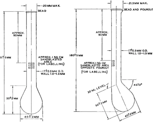
5 1 9 3 1 9 4Either of the two digestion flasks shown in Figs. 105, and 106 may be used, but the Soltys type is preferable when danger of spattering is great, particularly with the zinc-iron reduction procedure. The flasks should be made of shock- resistant glass with linear coefficient of expansion not greater than 33.5 X 10~
7cm./cm./°C.
DIGESTION K A C K5'1 9 3-1 9 4
The digestion rack consists of flask heaters, a flask support, and a fume duct.
(The fume duct has been referred to as a manifold in the past.) Suitable units are commercially available, such as those shown in Figs. 107 and 108. In general, they should conform to the following requirements.
HEATERS. The source of heat may be either electric or gas, but the author prefers the former. Each heater should have enough capacity so that it can
1 h
_ 1 I I B E /
APPROX.
90MM
I 8 0 Î 5 M M
2 0 MM MAX.
BEAD
1
APPROX.
9 0 MM
APPROX. I SQ CM SANDBLASTED , AREA . (FOR LABELLING) - — 1 7 - 0 . 5 M M O.D.
WALL I . 0 - L 3 M M
l e o t s M M
4-0 — 2MM
APPROX. ι sa CM SANDBLASTED AREA OPPOSITE POUROUT
(FOR LABELLING)
t
- ΑΓ\ A H 21.5 Κ 5 MM MAX.ί BEAD AND POUROUT
-17*0.5 MM O.D.
WALL 1.0-1.3 MM
FIG. 1 0 5 . (Left) Kjeldahl digestion flask, 3 0 ml.—details of construction.
FIG. 1 0 6 . (Right) Kjeldahl digestion flask, 3 0 ml., Soltys—details of construction.
supply sufficient heat to a 30 ml. flask to cause 15 ml. of water at 2 5 ° C. to come to a rolling boil (boiling chips) in not less than 2 or more than 3 minutes. Means should be provided for regulating the amount of heat sup
plied to each flask so that the above conditions can be met and also should be so adjustable that low-temperature digestions are possible. The switches and controls should be conveniently located and should remain cool even after long periods of operation.
FLASK S U P P O R T.5-1 9 3'1 9 4 The support on which the bulbs of the flasks rest
should shield the necks of the flasks from excessive heating during the digestion and should be provided with circular openings not exceeding 26 mm. in diameter, centered over each heater.
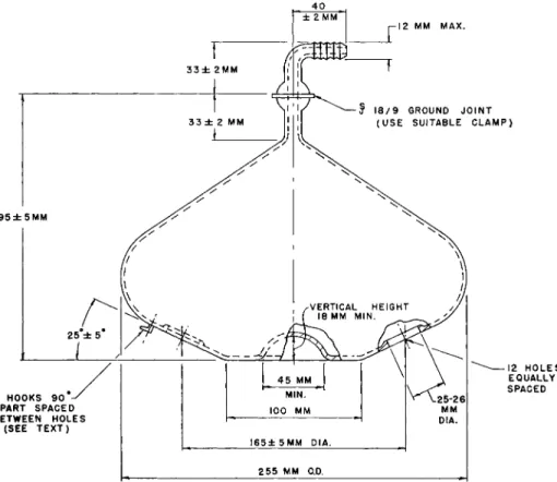
F U M E D U C T OR M A N I F O L D
.
5'
1 9 3'
1 9 4The fume duct should provide means for adequately removing by suction the fumes evolved during a digestion and should support the necks of the flasks at an angle greater than 3 5 ° to the
± 2 M M
-12 MM MAX.
S 18/9 GROUND JOINT (USE SUITABLE C L A M P )
I 9 5 ± 5 M M
25 ± 5
4 HOOKS 90 APART SPACED BETWEEN HOLES
(SEE TEXT)
45 MM MIN.
100 MM I 6 5 ± 5 M M DIA.
L25-26|
M M DIA.
255 MM O.D.
-12 H O L E S EQUALLY SPACED
FIG. 109. Fume duct (manifold) for circular type micro-Kjeldahl digestion rack—
details of construction.
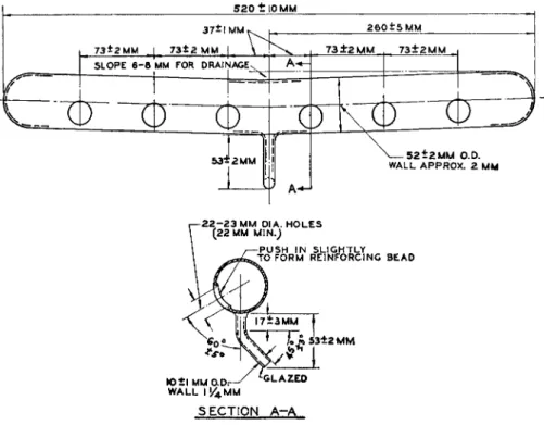
horizontal. Figures 109 and 110 show details of construction of fume ducts
used with setups of the types shown in Figs. 107 and 108, respectively. The
fume duct illustrated in Fig. 110 is supported and held in place by suitable
clamps mounted at either end of the digestion rack while the duct shown in
Fig. 109 rests upon a circular support plate and is held in place by springs
from the plate to the four glass hooks. The concave center permits clearance
for the nut which fastens the support plate to the center support post.
DISTILLATION APPARATUS
Either the one-piece m o d e l5'1 0'1 2 0'1 7 8'1 9 3-1 9 4 or the Pregl (Parnas-Wagner) 5>7 3·
7 4 , 1 3 7 , 1 3 8 , 1 5 7 , 1 6 3 - 1 6 6 , 1 9 3 , 1 9 4 t ype distillation apparatus may be used, but the author prefers the use of the former.*
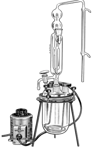
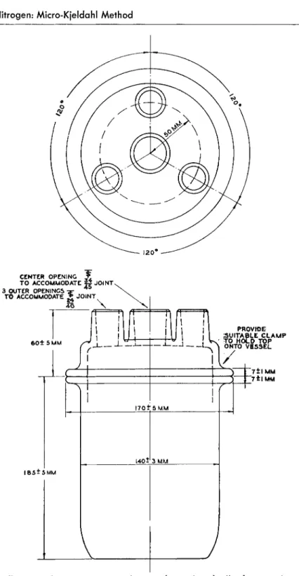
Ο Ν Ε - P I E C E DISTILLATION A P P A R A T U S.5'1 0-1 2 0'1 7 8'1 9 3'1 9 4 Steam is generated in the generator shown in Figs. I l l , 112, and 113 which consists of a wide- mouthed commercially available resin-reaction kettle and an immersion heater.
5 2 0 ± 1 0 M M 3 7 * 1 M MV
7 3 - 2 M M I 7 3 t 2 M M. j
2 6 0 ± 5 M M
S L O P E 6 - β MM FOR D R A I N A G EN
5 3 - 2 M M
7 3 ± 2 M M .
07
7 3 ± 2 M M
\ — 5 2 t 2 M M O . D . WALL A P P R O X . 2 MM
- 2 2 - 2 3 M M D I A . H O L E S ( 2 2 M M M I N . )
P U S H I N S L I G H T L Y F O R M R E I N F O R C I N G B E A D
3 ± 2 M M
I O± l M M O D i W A L L I ! 4 M M
S E C T I O N A - A
FIG. 110. Fume duct (manifold) for straight type micro-Kjeldahl digestion rack—
details of construction.
The interchangeable cover of the kettle, with flat-ground rim and four ground- glass tubulations, is held in place with a suitable clamp. The distillation unit is connected to the center tubulation. Two of the outer three tubulations are used for the leads of the immersion heater assembly, the heater of which should be of the type that does not burn out when not immersed. The remaining tubulation is used for adding water to the kettle. (Note: The addition of boric
* The one-piece model was designed by Dr. E. C. Noonan while he was working as a graduate student in the laboratory of Professor H. A. Iddles at the University of New Hampshire in 1935. His work was never published.
acid to the water in the vessel is recommended for reducing blank values.) The rate of steam generation is readily controlled by means of a 7.5 ampere
(minimum rating) variable transformer. The steam enters the distillationapparatus through the vertical tube extending almost halfway up the outer jacket at the left (Fig. 1 1 4 ) , surrounds the distillation flask proper (inner
FIG. 111. Micro-Kjeldahl distillation apparatus, one-piece model and steam generator assembly.
chamber), passes into the small bent tube near the top at the right (above the sample funnel inlet), then downward and through the bent portion of the tube at the lower end, and up into the inner chamber or distillation flask.
The steam then passes through the reaction mixture, traps, and condenser. The two traps with T-shaped tubes are very efficient for holding back alkali spray.
The outer jacket is equipped with a drain tube for removal of the spent
reaction mixture.
FIG. 1 1 2 . Steam generator vessel, 2 0 0 0- m l . capacity—details of construction.
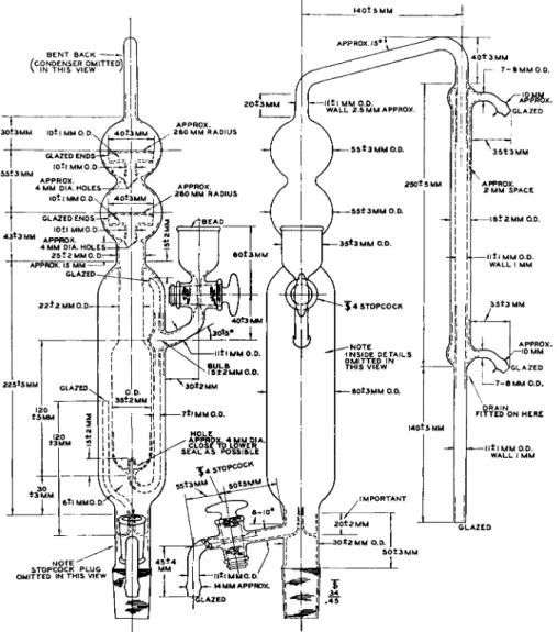
P R E G L T Y P E ( P A R N A S - W A G N E R ) DISTILLATION A P P A R A T U S .5'7 3'7 4'1 3 7-1 3 8- 157,163-6,193,194 The steam generator, consisting of the resin-reaction kettle and
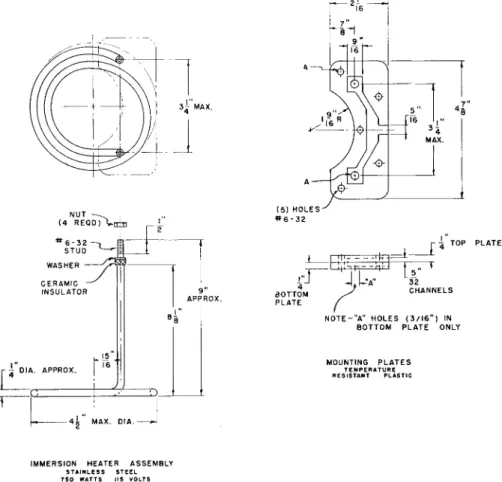
immersion heater (Figs. 112, 113, and 1 1 5 ) is also used with the Pregl type distillation apparatus. Besides the generator, the principal parts of the unit are the trap, distillation flask, and condenser. T h e trap is used both to collect
IMMERSION HEATER ASSEMBLY STAINLESS STEEL 7 5 0 WATTS 115 VOLTS
FIG. 113. Immersion heater assembly and mounting plates—details of construction.
condensate before it enters the distillation flask and to prevent the spent reaction mixture from entering the steam generator since, like the one-piece model, the Pregl type is automatically cleaned when steam generation is stopped.
The distillation flask has entrance tubes for both the steam from the steam
trap and for introduction of the digest through the funnel. T h e flask is equipped
with a vacuum jacket to facilitate the heating by the passage of steam. During
the distillation, steam enters and passes downward through the inner tube
which extends almost to the bottom of the flask. After passing through the reaction mixture it passes through the bulb and condenser. The condenser is of the West t y p e
1 9 3 , 1 9 4for more efficient cooling. Figure 115 shows the assembly and Figs. 115 B , 115 D , 115 E, 115 F, 115 G, 115 H, 115 J , 115 K, 115 L show the details of construction of the various parts shown in the assembly.
FIG. 114. Micro-Kjeldahl distillation apparatus, one-piece model—two views show
ing details of construction. Drain, Fig. 115 L, may be fitted in position marked "Drain fitted on here."
FIG. 1 1 5 . Micro-Kjeldahl distillation apparatus, Pregl (Parnas-Wagner) type as
sembly. ( A ) Steam generator. ( B ) Steam tube. ( C ) Immersion heater assembly. ( D ) Steam trap. ( E ) Tube. ( F ) Connecting tube. ( G ) Distillation flask. ( H ) Filling funnel.
( J ) Condenser tube. ( K ) Condenser jacket. ( L ) Drain. See details of construction in Figs. 1 1 2 , 1 1 3 , and 1 1 5 B - 1 1 5 L .
I 0 0 ± 5 M M
G L A Z E D
12 M M O.D. A P P R O X .
FIG. 115 B . Steam tube—details of construction.
The steam generator is connected to the steam trap by means of suitable rubber tubing. The connection between the trap and steam inlet tube on the distillation flask is also made by means of suitable rubber tubing (or, if desired, a ball and socket joint may be used). The funnel, through which the sample
^ B E A O
5 4 ± 2 MM WALL I 3/ 4 MM
^ 6 * 0 . 5 MM O.D.
WALL I MM 10 MM O.D. A P P R O X . G L A Z E D
GLAZED
IWlO MM O.D. APPROX.
- B Î 0 . 5 M M O.D.
W A L L I MM
G L A Z E D
6 0 t 2 M M
1
I t 6 0 Î 2 M M
_ JG L A Z E D
^ — 1 0 MM APPROX.
L —8* 0. 5 MM O.D.
WALL I MM -I0MM APPROX.
G L A Z E D
FIG. 1 1 5 D . (Left) Steam trap—de
tails of construction.
FIG. 1 1 5 E. (Top, right) T u b e - details of construction.
FIG. 1 1 5 F . (Bottom, right) Con
necting tube—details of construction.
Ε A T T A C H E D HERE
and also the sodium hydroxide-thiosulfate mixture is added, is connected to the distillation flask using rubber tubing as above. The trap portion of the distillation flask is joined to the condenser tube by means of a ball and socket joint lubricated with stopcock grease* and held together with a suitable clamp.f
* The author has found Sisco No. 3 0 0 g r e a s e ,1 7 8»1 9 3»1 9 8 to be very good for this purpose.
f Arthur H. Thomas Company2 0 2 clamps No. 3 2 4 1 are preferred by the author.
CONNECTS TO F—7
I 2 0 Î 5 M M 2 MM O.D.
WALL I.3MM
2 5 ± 2 MM O.D.
I MM APPROX.
GLAZED
"APPROX. 3 MM SPACE - NOTE : OUTER C HAMBER
EVACUATED TO AT LEAST I MICRON FIG. 115 G . Distillation flask—details of construction.
4 0 ± 2 M M G L A Z E D
3 5 ± 2 M M
y l 2 / 5 B A L L J O I N T
^G C O N N E C T S H E R E
7
^ A P P R O X . 2 M M D I A .\ O P E N I N G A T P O I N T * β . 5 - 7 MM(MAX)O.D.-H
WALL I MM
2 0 t 2 M M GLAZED
1 7 5 - 5 M M
2 5 Î 2 M M H
±
S E C T I O N A [ — 9 * 0 . 5 M M O. D .
W A L L I M M G L A Z E D
/J F I T S INSIDE
4 1 0
± 5 M M
JJL IT
-11*0.5 M M O.D.
WALL I J M M - 8 t 0 . 5 M M O.D.
W A L L I MM
3 5 * 2 MM
APPROX. 30* *MM
Π Τ θ INSIDE Κ <
h » — I 4 Î 2 M M O . D . WALL I j - M M
4·
G L A Z E D - ^ ( I F MADE O F G L A S S }
4 5 ± 2 M M 4 0 * 2 M M
8 t 0 . 5 M M O.D.
W A L L I M M 10 MM APPROX.
G L A Z E D
I I t 0.5 M M O.D.
WALL l - M M 4
3 5 Î 2 M M
3 5 * 2 MM
W A L L l ] M M 6 ± 0 . 5 M M O.D:
W A L L I M M
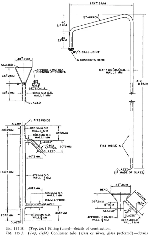
FIG. 115 H. (Top, left) Filling funnel—details of construction.
FIG. 115 J . (Top, right) Condenser tube (glass or silver, glass preferred)—details of construction.
FIG. 115 K . (Bottom, left) Condenser jacket (West-type)—details of construction.
FIG. 115 L. (Bottom, right) Drain—details of construction.
Regular Procedure*
About 5 mg. of sample (or enough to require several milliliters of 0 . 0 I N hydrochloric acid in the titration of the distilled ammonia) is weighed into a Kjeldahl flask, 30 ml., of the regular (Fig. 1 0 5 ) or the Soltys design (Fig.
1 0 6 ) . I f the sample is a solid, the weighing should be accomplished using a charging tube (see Figs. 4 7 - 4 9 , Chapter 3 ) . I f it is a high-boiling liquid, it is weighed in a porcelain boat (Fig. 22, Chapter 3 ) and the boat dropped into the flask. If this method is used, it might be necessary to use boiling chips to prevent bumping, during digestion, which might cause the boat to crack the flask. [Caution: Platinum boats or boiling chips (tetrahedra) should
never be used. When platinum is present during the digestion, the nitrogen is completely lost.192'225} A blank test should be run on the chips to make certainthat they do not contain traces of nitrogen. A volatile liquid sample is weighed in a capillary (Fig. 54, Chapter 3 ) which is broken below the surface of the digestion mixture (see below) with the aid of a glass rod. T o the flask are added 0.65 gramf of potassium sulfate, 0.016 gram of mercuric oxide, and 1 ml. of concentrated sulfuric acid sp. gr. 1.84, and the mixture is boiled on the digestion rack for 4 hoursf (suitable boiling chips may be added to prevent bumping). The mixture is boiled vigorously enough so that refluxing takes place about one-half way up in the neck of the flask. (Under these con
ditions t e s t s
1 9 2 , 1 9 3 , 2 2 1show that the temperature of the digestion mixture is approximately 340° C.) After the completion of the digestion, the digest is subjected to distillation as described below under (A) or (B).
(A) USING ONE-PIECE MODEL}
After digestion of the sample with mercuric oxide, potassium sulfate, and sul
furic acid, as described above, the contents of the Kjeldahl flask are diluted with 2 ml. distilled water and the rim of the flask coated with a thin film of stopcock grease. As a safety measure, to prevent possible suck back, the stopper should be left out of the tubulation (of the kettle cover) through which water is normally added. Then with both stopcocks (on sample funnel and on drain-
* Not applicable to compounds containing Ν—Ν, N = N , NO, N 02, and N 03 groups, except ^ Ν —> O.
f In a recent collaborative study,1 4 3 it was found that by using 1.00 gram of potassium sulfate and boiling for only one hour, satisfactory results are obtained. The increased tem
perature brought about by the increased amount of the salt used affects complete digestion in the shorter period of time. Extreme care should be exercised in the amount of potassium sulfate used because if more than this amount is used, the temperature will be too high and nitrogen will be lost.
ΐ Before being used each day, the apparatus should be cleaned by passing steam through it at a rapid rate for about 10 minutes. A new setup should be steamed out for considerably longer.
age tube) of the distillation apparatus open, the diluted digest is poured through the sample funnel (and the curved tube) into the inner chamber or dis
tillation flask. An additional 1 0 - 1 2 ml. of distilled water, in several 2 - 3 ml. por
tions, is then used in quantitatively transferring the contents of the digestion flask to the distillation flask. A 125-ml. Erlenmeyer flask containing 5 ml. of 4 % boric acid solution, and four drops of indicator (either bromocresol green-methyl red or methyl red-methylene blue), is placed under the delivery tube of the condenser, in a tilted manner so that the tip is well immersed in the liquid. A rapid stream of cold water is run through the condenser. Five milliliters of the sodium hydrox
ide-sodium thiosulfate mixture is carefully run into the distillation flask through the sample funnel. (Since the alkali enters from the bottom, it merely forces the acid layer upward and there is not as much danger of mixing as there is with the Pregl type of apparatus.) The stopper is replaced in the tubulation, both stopcocks are then closed and the steam generator switched on. Steam should pass through at a rather rapid rate but not at such that the strongly alkaline liquid mixture is splashed up into the portion at the top of the flask, below the traps, with the danger of alkaline spray being swept into the condenser.
The alkaline mixture in the distillation flask should be steam distilled for 5 minutes from the time that condensation begins in the condenser. The flask containing the boric acid is then lowered so that the tip of the condenser tube is in the neck of the flask, well above the surface of the solution. Steam distillation is continued for 2 to 3 minutes longer to wash out the condenser tip. A few milliliters of distilled water are then used to wash any solution adhering to the outside of the condenser tube into the flask. The boric acid solution of ammonia in the flask is then titrated with 0 . 0 I N hydrochloric acid to the endpoint. ( A second flask containing 5 ml. of boric acid, four drops of indicator, distilled water and an excess of 0 . 0 I N hydrochloric acid should be used for comparison purposes. )
Calculation: See below after description of procedure with Pregl-type
apparatus.
The apparatus may be cleaned by either of the following methods:
( 1 ) The steam generator is switched off and both stopcocks are allowed
to remain closed. The reduced pressure in the generator, brought about by the cooling, causes the alkaline mixture in the distillation flask to be sucked up through the vertical tube (on the right) and into the outer jacket (reverse of the path taken by the steam) where it can be discarded through the drainage stopcock and tube. Since the vertical tube on the left extends about halfway up the outer jacket, the alkaline mixture does not enter the steam generator.
Distilled water is then run into the distillation chamber through the sample
funnel. Both stopcocks are again closed and steam generated for about one
minute and then shut off. As described above, the rinse water is then auto-
matically sucked out of the distillation flask into the outer jacket and is discarded.
( 2 )5
When boiling chips are employed in the digestion the following is particularly satisfactory. The steam generator is switched off while both stop
cocks are closed. The reduced pressure in the generator, brought about by the cooling, causes the alkaline mixture in the distillation flask to be sucked into the outer jacket. Both stopcocks are opened to allow the liquid to drain off.
Then, while steam is being generated, both stopcocks are closed, the sample inlet funnel is filled with water, and the tip of the condenser is immersed in about 100 ml. of water in a beaker. Steam generation is stopped and the stopcock of the sample inlet funnel opened slowly just long enough to admit
almost all of the water from the funnel, after which it is closed. The resultingreduced pressure in the system causes the water to be sucked from the beaker into the apparatus, thereby washing it. The stopcock on the drainage tube is opened to empty the liquid that has collected in the outer jacket. I f necessary, steam generation may be started again and the rinsing repeated several times.
( 3 ) Instead of using the reduced pressure from the cooling to suck the rinse water through the system, a water suction pump may be used, attached to the drainage tube.
(B) USING THE PREGL DISTILLATION APPARATUS (PARNAS-WAGNER TYPE)*
With the distillation flask coolf and the pinch clamps on the filling funnel and on the steam trap open, steam is generated in the generator. With the apparatus so arranged most of the steam passes out through the bottom of the trap and a little passes out through the filling funnel. The diluted digestÎ is poured into the funnel and passes into the distillation flask. About 1 0 - 1 2 ml.
of distilled water is then used for quantitatively washing the contents of the Kjeldahl flask into the distillation flask. (The completeness of the rinsing can be tested by adding a drop of methyl orange to the digestion flask after the final rinse.
2 2 1) A 125-ml. Erlenmeyer flask containing 5 ml. of the boric acid solution and four drops of the indicator (either bromocresol green-methyl red or methyl red-methylene blue) is then placed under the delivery tube of the condenser and slightly tilted so that the tip extends well below the liquid
* Before the apparatus is used each day, it is thoroughly steamed out as stated above in connection with the one-piece model.
f I f the distillation flask is warm, as it cools air is sucked in through the inner tube leading to the bottom of the flask and causes stirring of the acid and alkali when the latter is added. This can cause a possible loss of ammonia, as there should be two distinct layers, acid on top to trap the ammonia, prior to the passage of steam through the mixture.
t Diluted with 2 ml. distilled water, as described above under (A) Using One- Piece Model.
surface. Five milliliters of the sodium hydroxide-sodium thiosulfate mixture is carefully added through the funnel so that two liquid layers are formed (acid on top, alkali on bottom). In this way the ammonia liberated on contact with alkali passes into the acid layer and is again converted to ammonium acid sulfate. The pinch clamps beneath the filling funnel and steam trap are closed in the respective order which causes steam to enter the tube leading to the bottom of the distillation flask, mixing the two layers. The resulting strongly alkaline mixture is steam distilled for 5 minutes (from the time that condensation begins in the condenser) with the end of the delivery tube below the surface of the boric acid and for an additional 2 - 3 minutes after the flask has been lowered so that the end of the tube is out of the liquid and up towards the neck of the flask. Steam distillation should be at a rather rapid rate with a
rapid stream of cold water passing through the condenser. However, the rateshould not be great enough so that the alkaline mixture splashes up into the bulb at the top of the distillation flask below the Kjeldahl trap and an alkaline spray is carried over into the condenser. The tip of the delivery tube of the condenser is washed with a few milliliters of distilled water to transfer any boric acid adhering to the outside into the flask. The boric acid solution of ammonia is then titrated with 0 . 0 I N hydrochloric acid to the end point. For comparison, a second flask containing 5 ml. boric acid, distilled water, four drops of indicator and an excess of 0 . 0 I N hydrochloric acid should be kept on the titration table.
The apparatus is automatically cleaned when the heat is removed from the steam generator at the completion of the steam distillation, if the two pinch clamps are kept tightly closed. The reduced pressure which results in the
closed steam generator, on cooling, causes the alkaline mixture to be suckedback into the steam trap which is then drained by opening the pinch clamp beneath it. Distilled water is introduced into the distillation flask through the filling funnel, both pinch clamps closed again, a little steam generated, and the system then allowed to cool, causing the rinse water to be sucked back into the trap as above. An alternate method of washing is the following: With both pinch clamps closed and steam being generated and passing through the system at a rapid rate, the end of the delivery tube of the condenser is sub
merged in distilled water. Heat is removed from the closed steam generator and the reduced pressure resulting on cooling causes the rinse water to be sucked up into the condenser, into the distillation flask and then into the trap from which it is drained.
Calculation:*
Each ml. of 0 . 0 I N hydrochloric acid is equivalent to 0.14008 mg. of nitrogen (see factors, Chapter 2 3 ) .
* Blank determinations should be made in the absence of a sample, using all reagents, and the value obtained subtracted.
ml. of 0.01N HC1 X 0.14008 X 100
Λ — % Ν W t . of sample
Example:
Suppose that 3.15 ml. of 0.01N hydrochloric acid is required to titrate the ammonia formed from a sample weighing 4.382 mg.
. 3.15 X 0.14008 X 100 ^ X T
= 10.07% Ν 4.382
The allowable error of the method is the same as that of the Dumas method, namely, ± 0 . 2 % .
Procedure for Determination of Nitrogen in Azo and Nitro Compounds, Oximes, Isoxazoles, Hydrazines,
and Hydrazones
From 5 to 8 mg. of sample, 0.2 ml. of 98 to 1 0 0 % formic acid, and 0.1 ml.
of concentrated hydrochloric acid, sp. gr. 1.18, in a 30-ml. micro-Kjeldahl flask (preferably, Soltys type), are heated in a water bath ( 8 0 to 8 5 ° C.) until the sample is dissolved. (With the few cases where solubility is not affected by formic acid, glacial acetic acid should be used instead.) T o this is added 80 mg. of zinc dust (nitrogen-free), and the contents mixed by swirling for about 2 minutes, and heated in the water bath for 5 additional minutes. Then 4 0 mg. of iron powder is added and the flask is swirled for 2 minutes to effect mixing. T o this are added 0.1 ml. of concentrated hydro
chloric acid, sp. gr. 1.18, and 0.15 ml. of ethanol, and the mixture is again heated for 5 minutes (water bath). Every 5 minutes a 0.1-ml. portion of concentrated hydrochloric acid is added, with swirling and heating in the water bath, until the iron is dissolved. While the flask is swirled under a hood, 1.0 ml. of concentrated sulfuric acid, sp. gr. 1.84, is added (cautiously), and the contents are warmed until the evolution of gas (hydrogen chloride) has subsided. Then 0.65 gram of potassium sulfate, 0.016 gram of mercuric oxide, and, finally, 0.5 ml. of concentrated sulfuric acid, sp. gr. 1.84, are added. (It is preferable to add the sulfuric acid in this manner rather than all at once, because the final 0.5 ml. can be used to wash down any materials adhering to the walls. )
The mixture is boiled on a micro-Kjeldahl digestion rack for 4 hours, making certain that boiling is vigorous enough so that refluxing takes place almost halfway up in the neck of the flask. The digest is transferred to the micro-Kjeldahl distillation apparatus (preferably the one-piece model), 7.5 ml.
of sodium hydroxide-sodium thiosulfate mixture are added, and the ammonia is distilled out into boric acid solution (8 minutes with the delivery tube below
the boric acid solution, 2 minutes with it above). The distillate is then titrated with 0.0 I N hydrochloric acid, using bromocresol green-methyl red (or methyl red-methylene blue) mixture as the indicator. A blank determination should be run using all of the materials, minus the sample, and going through the entire procedure. Any blank value so obtained should be subtracted.
Calculation: Same as above.
Procedure for Determination of Nitrogen in Nitrates
195In a 30-ml. micro-Kjeldahl flask are placed 5 to 8 mg. of sample, 35 mg. of salicylic acid and 1 ml. of concentrated sulfuric acid, sp. gr. 1.84. The mixture is first cooled and then allowed to stand at room temperature for 30 minutes, during which time nitration of the salicylic acid takes place. Then 100 mg. of crystalline sodium thiosulfate is added with cooling and the mixture is allowed to stand at room temperature for an additional 10 to 15 minutes. Finally 0.65 gram of potassium sulfate and 0.016 gram of mercuric oxide are added, and the mixture is boiled on the digestion rack in the usual manner for 4 hours.
A P P R O X . 9 0 M M
I 8 0 ± 5 M M
h
1 5 - 0 . 5 M M O . D . W A L L 1 . 0 - 1 . 3 MMFIG. 116. Kjeldahl digestion flask, 10 ml.—details of construction.
Distillation, titration, and blank determination are done as described under Regular Procedure.
Calculation : Same as above.
ADDITIONAL INFORMATION FOR CHAPTER 8
Figures 116 and 117 show two other sizes of digestion flasks sometimes used, namely the 1 0 -
5>
1 9 3>
1 9 4and 1 0 0 -
1 9 3>
1 9 4m l . sizes.
2 1 0 + 5 MM
2 1 . 5 _ o rBEAD A n
MM M A X .
APPROX. I SQ CM SANDBLASTED , AREA (FOR L A B E L L I N G )
2 0 ± 0 . 5 MM O.D.
WALL 1.0-1.5 MM
FIG. 117. Kjeldahl digestion flask, 100 ml.—details of construction.
T A B L E 19
ADDITIONAL INFORMATION ON R E F E R E N C E S * RELATED TO C H A P T E R 8
In addition to the procedures described in detail in the preceding pages of this chapter, the author wishes to call to the attention of the reader many of the investiga
tions in connection with the microdetermination of nitrogen by the Kjeldahl method. These are listed in Table 19 and the same plan is used here as was used in the preceding chapters. (See statement at top of Table 4 of Chapter 1, regarding completeness of this material.)
Books Collaborative studies
Association of Official Agricultural Acree, 1
Chemists, 6 Clark, 40
Belcher and Godbert, 21, 22 Lake, 107
Clark, E . P., 41 Ogg, 142, 143
Clark, S. J . , 42 Ogg and Willits, 145, 146
Furman, 66 Willits and Ogg, 2 1 6 - 2 2 0
Grant, 73, 74
Kirk, 98
Without microchemical balance
Milton and Waters, 130, 131 Niederl and McBeth, 136 Niederl and Niederl, 137, 138
Niederl and Sozzi, 1 3 9
Apparatus
Pregl, 157 Asami, 7
Roth, 1 6 3 - 1 6 6 Ballentine and Gregg, 10
Steyermark, 1 9 3 Berck, 24
General, miscellaneous, reviews
Brant and Sievers, 34, 35General, miscellaneous, reviews
British Standards Institution, 37American Instrument Company, 4 Clark, E. P., 40, 41
Bode, 26 Doherty and Ogg, 53
Bradstreet, 31 Eder, 55
Dittrich and deVries, 51 Furman, 66
Gomez Vigide, 70 Grant, 73, 74
Gonzalez Carrero, Carballido Ramallo, Hallett, 78
and Gomez Vigide, 7 1 , 72 Jenden and Taylor, 89
Hirai and Hayatsu, 85 Johanson, 90
Hu, 86 Kemmerer and Hallett, 9 3
Kainz, 9 1 Kirk, 9 6- 9 8
Kirk, 95, 98 Kirsten, 99
Levin, Oberholzer, and Whitehead, 112 Klingmuller, 101 Machemer and McNabb, 118 Leurquin and Delville, 111 McKenzie, Wake and Wallace, 124 Machemer and McNabb, 118 Rush, Cruikshank, and Rhodes, 167 Marino, 120
Schulek, Burger, and Fehér, 174 Miller, 126
Stegemann, 190 Mohlau, 132, 133
Stetten, 191 Niederl and Niederl, 137, 138
White and Secor, 211 Nogrâdy, 141
White, Secor, and Long, 212 Parnas, 149 Wingo, Davis, and Anderson, 222 Parnas, 150
* The numbers which appear after each entry in this table refer to the literature citations in the reference list at the end of the chapter.
T A B L E 19 (Continued) Apparatus (Con/.)
Parnas and Wagner, 151 Roth, 162
Scandrett, 169
Schôniger and Haack, 173 Sheers and Cole, 182 Shepard and Jacobs, 183 Sickels and Schultz, 185 Silverstein and Perthel, 186 Skidmore, 187
Willits, John, and Ross, 215 Digestion conditions
Acree, 1
Ballentine and Gregg, 10 Beatty, 12
Beet and Belcher, 16 Belcher and Godbert, 20 Bradstreet, 33
Briiel and Holter, 38 Clark, E. P., 40, 41 Cole and Parks, 43 Dalrymple and King, 44 Elek and Sobotka, 57 Harte, 79
Hartley, 80 Kaye and Weiner, 92 Lauro, 109
Miller, H. S., 127
Niederl and Niederl, 137, 138 Ogg, Brand, and Willits, 144 Osborn, 148
Parnas, 149
Parnas and Wagner, 151 Pepkowitz, Prince, and Bear, 153 Portner, 156
Pregl, 157
Schulek and Vastagh, 176 Steyermark, 193
Stubbleneld and Deturk, 197 Vene, 208
White and Secor, 211 Willits, Coe, and Ogg, 214 Zakrzewski and Fuchs, 224 Modifications
Beet, 13-15
Blom and Schwarz, 25
Modifications (Conf.) Bradstreet, 30 Breyhan, 36
Cepciansky and Chromcova, 39 Dermelj and Strauch, 4 6 - 4 8 Edwards, 56
Esafox, 58 Fawcett, 60 Fels and Veatch, 61 Fish and Collier, 64 Hayazu, 82 Hu, 86 Jacobs, 88
Kaye and Weiner, 92 Kirk, 96, 97
Lada and Usiekniewicz, 106 Lang, 108
Lestra and Roux, 110 Marzadro, 121-123 McKenzie and Wallace, 125 Milner and Zahner, 128 Môhlau, 132, 133 Mott and Wilkinson, 135 Noble, 140
Ogg, 143
Ogg and Willits, 145 Pepkowitz, 152
Pepkowitz, Prince, and Bear, 153 Pepkowitz and Shive, 154 Perrin, 155
Schôniger, 172
Silverstein and Perthel, 186 Terent'ev and Luskina, 201 Tourtellotte, Parker, Alving, and
De Jong, 204 Zinneke, 225
Sealed tube digestion Baker, 9
Grunbaum, Kirk, Green, and Koch, 75 Grunbaum, Schaffer and Kirk, 76 SchafTer and Sprecher, 170 White and Long, 210 Indicators
Grant, 73, 74 Kaye and Weiner, 92 Niederl and Niederl, 137, 138
T A B L E 19 (Continued) Indicators (Conf.)
Ogg, Brand, and Willits, 144 Pregl, 157
Roth, 1 6 3 - 1 6 6 Sher, 184
Taylor and Smith, 200 Wagner, 209 Catalysts
Baker, 8 Beatty, 12 Bradstreet, 3 1 - 3 3 Dalrymple and King, 44 Fawcett, 60
Fish and Collier, 64 Gomez Vigide, 70
Levin, Oberholzer, and Whitehead, 112 McKenzie and Wallace, 125
Rauen and Buchka, 159 Ribas and Lopez Capont, 160 Ribas and Vâzquez-Gesto, 161 Takeda and Senda, 199 White, Secor, and Long, 212 Ultra-, submicro methods
Baudet and Cherbuliez, 11 Belcher, Bhasin and West, 17 Belcher, West, and Williams, 23 Boissonnas and Haselbach, 27 Day, Bernstorf, and Hill, 45 Dixon, 52
Doyle and Omoto, 54 Exley, 59
Gaberman, 68
Grunbaum, Kirk, Green, and Koch, 75 Kirsten, 100
Kuck, Kingsley, Kinsey, Sheehan, and Swigert, 105
Okada and Hanafusa, 147 Schaffer and Sprecher, 170 Scheurer and Smith, 171 Schulek and Foti, 175 Shaw and Beadle, 181
Sobel, Mayer, and Gottfried, 189 Vallentyne, 205
Fluorine compounds Fennell and Webb, 62 Ma, 115
Ν—Ο, Ν—Ν compounds Baker, 9
Belcher, Bhasin, and West, 17 Belcher and Bhatty, 18 Bradstreet, 28, 29 Clark, Ε. P , 41 Dickinson, 49, 50 Fish, 63 Friedrich, 65 Grant, 73, 74 Hayazu, 83, 84 Konovalov, 102, 103
Kuch, Kingsley, Kinsey, Sheehan, and Swigert, 105
Ma, Lang, and McKinley, 116 Marzadro, 122
Ogg and Willits, 146 Pepkowitz, 152 Roth, 163-166
Secor, Long, Kilpatrick, and White, 179 Willits and Ogg, 218, 219
Iodometric procedures Morgulis and Friedman, 134 Rappaport, 158
Omission of distillation Adams and Spaulding, 3 Belcher and Bhatty, 19 Harvey, 81
Lestra and Roux, 110 Llacer, 113
Marcali and Rieman, 119 Taylor and Smith, 200 Elimination of titration
Taylor and Smith, 200 Also see Chapter 18
Spectrophotometry, colorimetric, chromatographic, etc., methods Boissonnas and Haselbach, 27 Gardon and Leopold, 69
Gonzales Carrero, Carballido Ramallo, and Gomez Vigide, 7 1 , 72
Hale, Hale, and Jones, 77 Kotlyarov, 104
Lubochinsky and Zalta, 114
T A B L E 19 (Continued) Spectrophotometry, colorimetric, Other methods
chromatographic, etc., methods Dumas, see Chapter 7 Hussey and Maurer, 87 King and Faulconer, 94 Manometric, see Chapter 18 Seligson and Seligson, 180 Slavik and Smetana, 188 Van Slyke, 206
Van Slyke and Kugel, 207 (Conf.)
Milner, Zahner, Hepner, and Cowell, 129 Scheurer and Smith, 171
Schwab and Caramanos, 177 Stone, 196
Thompson and Morrison, 203 Wust, 223
Zinneke, 225
R E F E R E N C E S
1. Acree, F., Jr., / . Assoc. Offic. Agr. Chemists, 24, 648 ( 1 9 4 1 ) .
2. Acculate, Anachemia Chemicals, Ltd., Montreal, Quebec, and Champlain, New York.
3. Adams, C. L, and Spaulding, G. H., Anal. Chem., 27, 1003 ( 1 9 5 5 ) .
4. American Instrument Co., Inc., "Digestion and Distillation Apparatus for the Micro Kjeldahl Nitrogen Determination," Bull. No. 2271, Silver Springs, Mary
land, 1955.
5. American Society for Testing Materials, AST M Designation, Ε 147-59 Τ ( 1 9 5 9 ) . 6. Association of Official Agricultural Chemists, "Official Methods of Analysis," 8th
ed., pp. 8 0 1 - 8 1 1 , Washington, D . C , 1955.
7. Asami, T., Anal. Chem., 31, 630 ( 1 9 5 9 ) . 8. Baker, P. R. W . , Analyst, 78, 500 ( 1 9 5 3 ) . 9. Baker, P. R. W., Analyst, 80, 481 ( 1 9 5 5 ) .
10. Ballentine, R., and Gregg, J . R., Anal. Chem., 19, 281 ( 1 9 4 7 ) .
11. Baudet, P., and Cherbuliez, E., Helv. Chim. Acta, 40, 1612 ( 1 9 5 7 ) ; Chem.
Abstr., 53, 15328 ( 1 9 5 8 ) .
12. Beatty, C , III, Ind. Eng. Chem., Anal. Ed., 15, 476 ( 1 9 4 3 ) . 13. Beet, A. E , / . Appt. Chem. (London), 4, 373 ( 1 9 5 4 ) . 14. Beet, A. E., Nature, 175, 513 ( 1 9 5 5 ) .
15. Beet, A. E., Fuel. Soc. J. Sheffield Univ., 6, 12 ( 1 9 5 5 ) . 1 6 . Beet, A. E., and Belcher, R., Mikrochemie, 24, 145 ( 1 9 3 8 ) .
17. Belcher, R., Bhasin, R. L., and West, T . S., / . Chem. Soc, p. 2585 ( 1 9 5 9 ) . 18. Belcher, R., and Bhatty, M. K., Analyst, 81, 124 ( 1 9 5 6 ) .
19. Belcher, R., and Bhatty, M. K., Mikrochim. Acta, p. 1183, 1956.
20. Belcher, R., and Godbert, A. L., / . Soc. Chem. Ind. (London), 60, 196 ( 1 9 4 1 ) . 21. Belcher, R., and Godbert, A. L., "Semi-Micro Quantitative Organic Analysis,"
Longmans, Green, London, New York, and Toronto, 1945.
22. Belcher, R., and Godbert, A. L., "Semi-Micro Quantitative Organic Analysis," 2nd ed., Longmans, Green, London, 1954.
23. Belcher, R., West, T. S., and Williams, M., / . Chem. Soc, p. 4323 ( 1 9 5 7 ) . 24. Berck, B . , Chemist Analyst, 43, 52 ( 1 9 5 4 ) .
25. Blom, J . , and Schwarz, B . , Acta Chem. Scand., 3, 1439 ( 1 9 4 9 ) . 26. Bode, F., Experientia, 9, 271 ( 1 9 5 3 ) .
27. Boissonnas, R. Α., and Haselbach, C. H., Helv. Chim. Acta, 36, 576 ( 1 9 5 3 ) . 28. Bradstreet, R. B . , Anal. Chem., 26, 185 ( 1 9 5 4 ) ; Anal Abstr., 1, No. 1278 ( 1 9 5 4 ) . 29. Bradstreet, R. B . , Anal. Chem., 26, 235 ( 1 9 5 4 ) ; Anal. Abstr., 1, No. 1279 ( 1 9 5 4 ) .
30. Bradstreet, R. B., Anal. Chem., 32, 114 ( i 9 6 0 ) . 31. Bradstreet, R. B . , Chem. Revs., 27, 331 ( 1 9 4 0 ) .
32. Bradstreet, R. B., Ind. Eng. Chem., Anal. Ed., 10, 696 ( 1 9 3 8 ) . 33. Bradstreet, R. B., Ind. Eng. Chem., Anal. Ed., 12, 657 ( 1 9 4 0 ) .
34. Brant, J . H , and Sievers, D. C , Ind. Eng. Chem., Anal. Ed., 12, 133 ( 1 9 4 0 ) . 35. Brant, J . H., and Sievers, D. C , Ind. Eng. Chem, Anal. Ed., 13, 133 ( 1 9 4 1 ) . 36. Breyhan, T., Ζ. anal. Chem., 152, 412 ( 1 9 5 6 ) .
37. British Standards Institution, Brit. Standards, 1428, Pt. B l , and Pt. B2 ( 1 9 5 3 ) . 38. Briiel, D., and Holter, H., Compt. rend. trav. lab. Carlsberg. Sér. chim., 25, 289
( 1 9 4 7 ) .
39. Cepciansky, I., and Chromcova, L., Chem. prûmysl, 9, 188 ( 1 9 5 9 ) ; Anal. Abstr., 6, No. 4802 ( 1 9 5 9 ) .
40. Clark, E. P., / . Assoc. Offic. Agr. Chemists, 24, 641 ( 1 9 4 l ) .
41. Clark, E. P., "Semimicro Quantitative Organic Analysis," Academic Press, New York, 1943.
42. Clark, S. J . , "Quantitative Methods of Organic Microanalysis," Butterworths, London, 1956.
43. Cole, J . O., and Parks, C. R., Ind. Eng. Chem., Anal. Ed., 18, 61 ( 1 9 4 6 ) . 44. Dalrymple, R. S., and King, G. B., Ind. Eng. Chem., Anal. Ed., 17, 403 ( 1 9 4 5 ) . 45. Day, H. G., Bernstorf, E., and Hill, R. T., Anal. Chem., 21, 1290 ( 1 9 4 9 ) .
46. Dermelj, M., and Strauch, L., Bull. sci. Conseil acad. RPF Yougoslavie, 3, 6 ( 1 9 5 6 ) .
47. Dermelj, M., and Strauch, L., Mikrochim. Acta, p. 96 ( 1 9 5 7 ) .
48. Dermelj, M., and Strauch, L., Vestnik. Sloven, kemi. drustva, 2, 77 ( 1 9 5 5 ) . 49. Dickinson, W . E., Anal. Chem., 26, 777 ( 1 9 5 4 ) .
50. Dickinson, W . E., Anal. Chem., 30, 992 ( 1 9 5 8 ) .
51. Dittrich, S., and Vries, J . X . de, pR {Montevideo), 5, 78D ( 1 9 5 5 ) ; Chem. Abstr., 52, 169 ( 1 9 5 8 ) .
52. Dixon, J . P., Anal. Chim. Acta, 13, 12 ( 1 9 5 5 ) .
53. Doherty, D . G., and Ogg, C. L., Ind. Eng. Chem., Anal. Ed., 15, 751 ( 1 9 4 3 ) . 54. Doyle, W . L., and Omoto, J . H., Anal. Chem., 22, 603 ( 1 9 5 0 ) .
55. Eder, K., Mikrochim. Acta, p. 227 ( 1 9 5 7 ) .
56. Edwards, A. H., / . Appl. Chem. (London), 4, 330 ( 1 9 5 4 ) . 57. Elek, Α., and Sobotka, H., / . Am. Chem. Soc, 48, 501 ( 1 9 2 6 ) . 58. Esafox, V . I., Zavodskaya Lab., 21, 1160 ( 1 9 5 5 ) .
59. Exley, D., Biochem. ] . , 63, 496 ( 1 9 5 6 ) .
60. Fawcett, J . K., / . Med. Lab. Technol., 12, 1 ( 1 9 5 4 ) . 61. Fels, G., and Veatch, R., Anal. Chem., 31, 451 ( 1 9 5 9 ) .
62. Fennell, T. R. F. W., and Webb, J . R., Analyst, 83, 694 ( 1 9 5 8 ) . 63. Fish, V . B , Anal. Chem., 24, 760 ( 1 9 5 2 ) .
64. Fish, V . B . , and Collier, P. R., Anal. Chem., 30, 151 ( 1 9 5 8 ) . 65. Friedrich, Α., Ζ. physiol. Chem. Hoppe-Seyler9s, 216, 68 ( 1 9 3 3 ) .
66. Furman, Ν. H., ed., "Scott's Standard Methods of Chemical Analysis," 5th ed., Vol. II, Van Nostrand, New York, 1939.
67. Furter, M. F., Personal communication.
68. Gaberman, V., Voprosy Med. Khim., 3, 464 ( 1 9 5 7 ) ; Chem. Abstr., 52, 12663 ( 1 9 5 8 ) .
69. Gardon, J . L., and Leopold, B., Anal. Chem., 30, 2057 ( 1 9 5 8 ) .
70. Gomez Vigide, R. F., Inform, qutm. anal. (Madrid), 12, 9 ( 1 9 5 8 ) ; Anal. Abstr., 5, No. 3767 ( 1 9 5 8 ) .
71. Gonzalez Carrero, J . , Carballido Ramallo, O., and Gomez Vigide, F., Inform.
quim. anal. (Madrid), 10, 199 ( 1 9 5 6 ) .
72. Gonzalez Carrero, J . , Carbillado Ramallo, O., and Gomez Vigide, F., Proc. Intern.
Cong. Pure and Appl. Chem., Anal. Chem. 15th Congr., Lisbon, 1, 101 ( 1 9 5 6 ) ; Anal. Abstr., 6, No. 1175 ( 1 9 5 9 ) .
73. Grant, J . , "Quantitative Organic Microanalysis, Based on the Methods of Fritz Pregl," 4th ed., Blakiston, Philadelphia, Pennsylvania, 1946.
74. Grant, J . , "Quantitative Organic Microanalysis," 5th ed., Blakiston, Philadelphia, Pennsylvania, 1951.
75. Grunbaum, B . W . , Kirk, P. L., Green, L. G., and Koch, C. W . , Anal. Chem., 27, 384 ( 1 9 5 5 ) .
76. Grunbaum, B . W . , Schaffer, F. L., and Kirk, P. L., Anal. Chem., 24, 1487 ( 1 9 5 2 ) . 77. Hale, C. H., Hale, M. N., and Jones, W . H., Anal. Chem., 21, 1549 ( 1 9 4 9 ) . 78. Hallett, L. T., Ind. Eng. Chem., Anal. Ed., 14, 956 ( 1 9 4 2 ) .
79. Harte, R. Α., Ind. Eng. Chem., Anal. Ed., 7, 432 ( 1 9 3 5 ) . 80. Hartley, O., Ind. Eng. Chem., Anal. Ed., 6, 249 ( 1 9 3 4 ) . 81. Harvey, H. W . , Analyst, 76, 657 ( 1 9 5 1 ) .
82. Hayazu, R., Yakugaku Zasshi, 70, 357 ( 1 9 5 0 ) . 83. Hayazu, R., Yakugaku Zasshi, 71, 135 ( 1 9 5 1 ) . 84. Hayazu, R., Yakugaku Zasshi, 71, 207 ( 1 9 5 1 ) .
85. Hirai, M., and Hayatsu, R., Yakugaku Zasshi, 71, 765 ( 1 9 5 1 ) .
86. Hu, C.-C, Hua Hsueh Shih Chieh, p. 131 ( 1 9 5 9 ) ; Chem. Abstr., 53, 21396 ( 1 9 5 9 ) .
87. Hussey, A. S., and Maurer, J . E., Anal. Chem., 24, 1642 ( 1 9 5 2 ) . 88. Jacobs, M. B . , / . Am. Pharm. Assoc. Sci. Ed., 40, 151 ( 1 9 5 1 ) . 89. Jenden, D . J . , and Taylor, D . B . , Anal. Chem , 25, 685 ( 1 9 5 3 ) . 90. Johanson, R., / . Proc. Australian Chem. Inst., 15, 183 ( 1 9 4 8 ) . 91. Kainz, G., Ôsterr. Chemiker-Ztg., 57, 242 ( 1 9 5 6 ) .
92. Kaye, I. Α., and Weiner, N., Ind. Eng. Chem., Anal. Ed., 17, 397 ( 1 9 4 5 ) . 93. Kemmerer, G., and Hallett, L. T., Ind. Eng. Chem., 19, 1295 ( 1 9 2 7 ) . 94. King, R. W., and Faulconer, W . Β . M., Anal. Chem., 28, 255 ( 1 9 5 6 ) . 95. Kirk, P. L., Anal. Chem., 22, 354 ( 1 9 5 0 ) .
96. Kirk, P. L., Ind. Eng. Chem., Anal. Ed., 8, 223 ( 1 9 3 6 ) . 97. Kirk, P. L., Mikrochemie, 16, 13 ( 1 9 3 4 ) .
98. Kirk, P. L., "Quantitative Ultramicroanalysis," Wiley, New York, and Chapman
& Hall, London, 1 9 5 0 ; "The Chemical Determination of Proteins," in "Ad
vances in Protein Chemistry" ( M . L. Anson, and J . T . Edsall, eds.), Vol. 3, Academic Press, New York, 1947.
99. Kirsten, W., Anal. Chem., 24, 1078 ( 1 9 5 2 ) . 100. Kirsten, W . J . , Microchem. ] . , 2, 179 ( 1 9 5 8 ) . 101. Klingmuller, V., Z. anal. Chem., 131, 17 ( 1 9 5 0 ) . 102. Konovalov, Α., Ind. chim. beige, 18, 329 ( 1 9 5 3 ) .
103. Konovalov, Α., Ind. chim. beige, 24, 259 ( 1 9 5 9 ) ; Anal. Abstr., 6, No. 4803 ( 1 9 5 9 ) . 104. Kotlyarov, I. I., Fiziol. Zhur. S.S.S.R., 33, 123 ( 1 9 4 7 ) .
105. Kuck, J . Α., Kingsley, Α., Kinsey, D., Sheehan, F., and Swigert, G. F., Anal.
Chem., 22, 604 ( 1 9 5 0 ) .
106. Lada, Z., and Usiekniewicz, K., Chem. Anal. (Warsaw), 2, 351 ( 1 9 5 7 ) ; Chem Abstr., 52, 4395 ( 1 9 5 8 ) .
107. Lake, G. R., Anal. Chem., 24, 1806 ( 1 9 5 2 ) . 108. Lang, C. Α., Anal. Chem., 30, 1692 ( 1 9 5 8 ) .
109. Lauro, M. F., Ind. Eng. Chem., Anal. Ed., 3, 401 ( 1 9 3 1 ) .
110. Lestra, H., and Roux, G., Compt. rend. acad. sci., 233, 1453 ( 1 9 5 1 ) . 111. Leurquin, J . , and Delville, J . P., Experientia, 6, 274 ( 1 9 5 0 ) .
112. Levin, B . , Oberholzer, V . G., and Whitehead, T. P., Analyst, 75, 561 ( 1 9 5 0 ) . 113. Llacer, A. J . , Mikrochemie ver. Mikrochim. Acta, 40, 173 ( 1 9 5 3 ) .
114. Lubochinsky, B., and Zalta, J . P., Bull. soc. chim. biol, 36, 1363 ( 1 9 5 4 ) . 115. Ma, T. S., Microchem. J . , 2, 91 ( 1 9 5 8 ) .
116. Ma, T. S., Lang, R. E., and McKinley, J . D., Jr., Mikrochim. Acta, p. 368 ( 1 9 5 7 ) . 117. Ma, T. S., and Zuazaga, G., Ind. Eng. Chem., Anal. Ed., 14, 280 ( 1 9 4 2 ) .
118. Machemer, P. E., and McNabb, W . M., Anal. Chim. Acta, 3, 428 ( 1 9 4 9 ) .
119. Marcali, K., and Rieman, Wm., I l l , Ind. Eng. Chem., Anal. Ed., 18, 709 ( 1 9 4 6 ) . 120. Marino, S. P., Chemist Analyst, 39, 42 ( 1 9 5 0 ) .
121. Marzadro, M., Mikrochemie ver. Mikrochim. Acta, 36/37, 671 ( 1 9 5 1 ) . 122. Marzadro, M., Mikrochemie ver. Mikrochim. Acta, 38, 372 ( 1 9 5 1 ) . 123. Marzadro, M., Mikrochemie ver. Mikrochim. Acta, 40, 359 ( 1 9 5 3 ) .
124. McKenzie, Η. Α., Wake, R. G., and Wallace, H. S., Proc. Intern. Congr. Pure and Appt. Chem., Anal. Chem. 15th Congr., Lisbon 1 ( 1 9 5 6 ) ; Anal. Abstr., 6, No.
1175 ( 1 9 5 9 ) .
125. McKenzie, Η. Α., and Wallace, H. S., Australian ] . Chem., 7, 55 ( 1 9 5 4 ) . 126. Miller, S. P., Chemist Analyst, 43, 52 ( 1 9 5 4 ) .
127. Miller, H. S., Ind. Eng. Chem., Anal. Ed., 8, 50 ( 1 9 3 6 ) . 128. Milner, Ο. I., and Zahner, R. J . , Anal. Chem., 32, 294 ( i 9 6 0 ) .
129. Milner, O. L, Zahner, R. J , Hepner, L. S., and Cowell, W . H., Anal. Chem., 30, 1528 ( 1 9 5 8 ) .
130. Milton, R. F., and Waters, W . Α., "Methods of Quantitative Microanalysis,"
Longmans, Green, New York, and Arnold, London, 1949.
131. Milton, R. F., and Waters, W . Α., "Methods of Quantitative Microanalysis," 2nd ed., Arnold, London, 1955.
132. Môhlau, E., Pharm. Zentralhalle, 89, 105 ( 1 9 5 0 ) . 133. Môhlau, Ε., Pharm. Zentralhalle, 89, 334 ( 1 9 5 0 ) .
134. Morgulis, S. M., and Friedman, A. F., Bull. soc. chim. biol, 18, 1074 ( 1 9 3 7 ) . 135. Mott, R. Α., and Wilkinson, Η. Α., Fuel, 37, 151 ( 1 9 5 8 ) .
136. Niederl, J . B . , and McBeth, C. H., Mikrochemie ver. Mikrochim. Acta, 35, 98 ( 1 9 5 0 ) .
137. Niederl, J . B . , and Niederl, V., "Micromethods of Quantitative Organic Elementary Analysis," Wiley, New York, 1938.
138. Niederl, J . B . , and Niederl, V., "Micromethods of Quantitative Organic Analysis,"
2nd ed., Wiley, New York, 1942.
139. Niederl, J . B . , and Sozzi, J . Α., "Microanâlisis Elemental Orgânico," Calle Arcos, Buenos Aires, 1958.
140. Noble, E. D., Anal. Chem., 27, 1413 ( 1 9 5 5 ) . 141. Nogrâdy, G., Magyar Kern. Lapja, 4, 350 ( 1 9 4 9 ) . 142. Ogg, C. L., / . Assoc. Offic. Agr. Chemists, 38, 365 ( 1 9 5 5 ) . 143. Ogg, C. L., / . Assoc. Offic. Agr. Chemists, 43, 682, 689 ( I 9 6 0 ) .
144. Ogg, C. L., Brand, R. W., and Willits, C. O., / . Assoc. Offic. Agr. Chemists, 31, 663 ( 1 9 4 8 ) .
145. Ogg, C. L., and Willits, C. O., / . Assoc. Offic. Agr. Chemists, 33, 100 ( 1 9 5 0 ) . 146. Ogg, C. L., and Willits, C. O., / . Assoc. Offic. Agr. Chemists, 35, 288 ( 1 9 5 2 ) 147. Okada, Y . , and Hanafusa, H., Bull. Chem. Soc. Japan, 27, 478 ( 1 9 5 4 ) . 148. Osborn, R. Α., / . Assoc. Offic. Agr. Chemists, 16, 107 ( 1 9 5 3 ) ; 18, 604 ( 1 9 3 5 ) .