CHAPTER J
Microdetermination of Nitrogen by the Dumas Method
The micro-Dumas,* sometimes called the ultimate or gasometric method for the determination of nitrogen is based on the fact that organic compounds con
taining nitrogen, when decomposed at red heat with copper oxide yield nitrogen and some oxides of nitrogen. The oxides of nitrogen are reduced to nitrogen by a section of reduced copper. The reactions involved are represented by the following:
Organic Ν > N2 + Ν oxides + C 02 - f H00 + Cu CuO
Ν oxides > N2 + CuO Cu
02 > CuO
" Cu
The entire procedure is carried out in an atmosphere of pure carbon dioxide after which the liberated nitrogen is swept from the tube with carbon dioxide and collected over potassium hydroxide. The volume of nitrogen is read at atmospheric pressure and its weight is calculated from the volume, pressure, and temperature.
This method was believed to successfully handle all types of compounds but experience has taught that many substances require some modifica- t i o n .
1 1'
1 2'
5 8'
5 9'
6 5'
6 6'
9 3'
1 3 9'
1 4 0'
1 6 2-
1 6 6'
1 8 6'
2 1 1-
2 1 2Unless experience has shown that the type to be analyzed gives difficulties, no modification should be used. Pyrimi- dines often give low results unless copper acetate
6 6or potassium chloratef or b o t h
1 2 0'
1 3 9'
1 4 0'
1 6 6-
1 8 1'
1 8 6-
1 8 8are added along with the sample. Compounds con
taining N-methyl groups also give low results probably due to formation of methylaminef instead of nitrogen.
1 8 6*
1 8 8The addition of copper acetate and
* Please see references 11, 12, 27, 4 8 , 58, 59, 65, 121, 122, 1 3 9 - 1 4 1 , 158, 163-166, 186, 212.
f The potassium chlorate liberates oxygen to aid in the combustion. The excess oxygen is trapped on the reduced copper.
ΐ The methylamine partially dissolves in the K O H . This idea is substantiated by the fact that these same substances when determined by the Kjeldahl method yield methyl amine instead of a m m o n i a .1 8 6*1 8 8 The former can be detected by odor on making the distillate akaline—see Chapter 8.
151
potassium chlorate often causes the combustion to go to completion. Sul
fonamides, hydrazines, hydrazones, semicarbazides, and nitrates often give low results and the addition* of potassium d i c h r o m a t e
4 8'
5 8-
5 9'
1 6 6'
1 8 6 , 1 8 8or vanadium pentoxide to the sample is useful in these cases. However, many compounds are better analyzed by the Kjeldahl method, regular, or one of the two modifica
tions described in Chapter 8. I f samples, such as hydrazines, nitro-compounds, nitrates, etc., fail to give good results using the Dumas method, attempts should be made with the Kjeldahl, unless the samples are known to contain nitrogen linked to nitrogen in a ring, such as pyrazolones, 1,2-diazines, 1,2,3,- triazoles, etc. Nitrogen connected to oxygen (ring or chain) and nitrogen con
nected to nitrogen in a chain may be analyzed by the latter method—see Chap
ter 8. Substances containing long aliphatic chains often give very high re- s u l t s
9 3 , 1 8 6'
1 8 8due to the formation of methane instead of carbon dioxide during the combustion. Potassium chlorate and copper acetate are often useful in correcting this c o n d i t i o n .
1 8 6 , 1 8 8Reagents
POTASSIUM HYDROXIDE SOLUTION, 5 0 %
Reagent grade of potassium hydroxide pellets are dissolved in an equal weight of distilled water and stored in a rubber-stoppered Pyrex flask. This is used in the m i c r o n i t r o m e t e r .
4 8'
5 8'
5 9'
1 2 1'
1 2 2'
1 3 9-
1 4 1'
1 5 8'
1 6 3-
1 6 6-
1 8 6MERCURY
About 15 ml. of mercury is used in the lower part of the reservoir of the micronitrometer.
CALOMEL
A few milligrams of c a l o m e l
1 3 7'
1 5 7-
1 8 6are used in the micronitrometer to prevent gas bubbles from sticking to the mercury surface.
STOPCOCK GREASE
Sisco No. 300 high-vacuum stopcock greasef is the best lubricant for the micronitrometer stopcock. When some of the other greases are used there is considerable frothing of the potassium hydroxide solution which makes read
ing of the meniscus impossible. With the Sisco No. 300, there is no frothing.
It is also used to lubricate the ball and socket joint attaching the needle valve and the micronitrometer—see below.
* The dichromate or varadium pentoxide must be kept in contact with the sample.
Therefore, the normal method of mixing the sample with the copper oxide in the tube as described later is dispensed with.
f Swedish Iron and Steel Corp., Westneld, New Jersey.
153 Reagents
KROENIG GLASS CEMENT1™
Kroenig glass cement is used for sealing the joints on the combustion tube to those on the carbon dioxide generator and the needle valve—see below.
It is warmed, applied, and allowed to cool to effect the seals.
COPPER TURNINGS (METALLIC)
Clean, degreased copper turnings are used as a section of reduced copper in the combustion tube.
COPPER OXIDE (CuO)
Two sizes of copper oxide are required, namely, coarse and fine powder.
Reagent grade of copper oxide (CuO) wire is ground in a mortar and pestle
so that the pieces are about 1-3 mm. in length. The fine powder is obtained by grinding until the material will pass through sieves of 40-100-mesh. Before using, both sizes of copper oxide must be conditioned in the following manner.
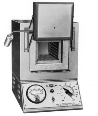
The material is put into nickel or stainless steel crucibles and then placed in a muffle furnace of the type shown in Fig. 88 which has a small hole opening in the door. Into this hole is inserted a small piece of quartz, Pyrex 1 7 2 0 * glass,
* Corning Glass Works, Corning, New York.
FIG. 88. Muffle furnace.
or metal tubing through which is passed a stream of carbon dioxide from a cylinder. The muffle is then heated to about 7 0 0 ° C . and kept at this temperature for 1 0 - 1 5 minutes. The muffle is then allowed to cool to room temperature during which time the stream of carbon dioxide is continued. The copper oxide is then removed from the muffle and stored in screw cap closed bottles. (The two sizes of copper oxide may be mixed for the conditioning and separated by sifting after being removed from the muffle.)
The above treatment destroys any organic material present and drives out pocketed air and replaces it with carbon dioxide. This eliminates any con
tamination and the replacing of air by the carbon dioxide makes it possible to obtain a much better grade of so-called microbubbles during the determina
tion (see below—Procedure).
The copper oxide (both sizes) is used over and over again. After each determination the temporary filling (see below—Procedure) is removed, treated with carbon dioxide at 7 0 0 ° C , cooled in an atmosphere of carbon dioxide, sifted to separate the two sizes and reused for another determination.
Some of the copper oxide is reduced to metallic copper during the course of each determination. This does not need to be oxidized. In fact, its presence is possibly advantageous as it would act similarly to having additional bands of reduced copper, which is the practice in one large laboratory.
2 1 1 , 2 1 3DRY ICE
A pure grade of dry ice (solid C 0
2) is used as a source of carbon dioxide.
Apparatus
The apparatus consists of a train composed of the following pieces, connected to each other in the order named: ( 1 ) source of carbon dioxide, ( 2 ) com
bustion tube containing copper oxide and copper, ( 3 ) needle valve for regulating the flow of gas through the train, and ( 4 ) the micronitrometer containing potassium hydroxide over which the nitrogen is collected and the carbon dioxide is absorbed. The combustion tube is surrounded by the heating elements of a combustion apparatus, which has two parts, namely, the long stationary furnace* and the short movable or sample furnace.* All of these parts are described in detail in the following pages.
* Common practice has been to refer to these parts as the "long burner" and "short burner" or "sample burner" and the entire outfit as the "combustion furnace." The new Tentative Spécifications for the Apparatus for the Microdetermination of Nitrogen by the Dumas Method of the American Society for Testing Materials,4 however, refer to the two parts as the "long furnace" and the "sample furnace."
155 Apparatus
DEWAR (THERMOS) F L A S K6 5 , 9 3'1 6 5'1 6 9'1 8 2'1 8 6 , 2 1 9
A 2-liter (1.5 minimum) thermos flask (bottle) of the type shown in Figs.
89, and 94 is used as a carbon dioxide generator. As a safety measure, the flask should be completely wrapped with some form of adhesive tape to prevent shattering in case of breakage. It is filled with powdered dry ice as described below. In the top of the flask is a two-hole rubber stopper. Through one of these holes is a glass tube which connects the flask, through a stopcock, to the combustion tube by means of a 1 4 / 3 5 interchangeable ground joint (female member of the joint on the generator end)—see Figs. 89, and 94. In the other hole of the rubber stopper is a bent glass tube which leads to the bottom of a cylinder of water approximately 3 7 - 4 0 cm. in height (an ordinary 1-liter graduate cylinder is quite satisfactory). By this means, the excess C 0
2escapes through the head of water and maintains the gas under constant pressure.
(Instead of the tube extending to the bottom of the water-filled graduate cylinder, the mercury valve shown in Fig. 102 may be used.)
Pure dry ice is crushed and ground to the size of rice grains, or smaller, by means of a mortar and pestle.* This removes air pockets from the material.
The powdered dry ice is placed in the Dewar (thermos) flask, the stopper with the tube in the cylinder of water is attached and the system allowed to blow off the excess pressure overnight to rid the system of air before using for a determination. A good 2-liter vacuum bottle will continue to give C 0
2for about 10 days.
COMBUSTION APPARATUS
A unit of the type shown in Fig. 89 (one of those in use in the author's laboratories) is required for the determination. This combustion apparatus consists of a long furnace and a power driven f short or sample furnace. The furnaces are composed of nichrome wire windings in asbestos blocks J and are of the split type that can be pushed back away from the combustion tube.
The long furnace is 205 mm. in length and can accommodate combustion tubes whose outside diameters are up to 13 mm. The short furnace also ac
commodates this size tube and is 110 mm. in length. The windings of each are of such resistance, that when operated through a variable auto-transformer, the desired operating temperature of 680° C , in the combustion tube, may
* Where a number of units are in operation, a power-driven dry ice pulverizer is recommended. Such units are commercially available, made by Franklin P. Miller & Son, Inc., 36 Meadow Street, East Orange, New Jersey (their model Supreme 16 Pulverizer is used by the author).
f Electric clock m o t o r s1 8 5 are quite suitable for this purpose as their r.p.m. is low enough so that they need no reduction gear system. Some of the available commercial furnaces are not mechanized and the above furnishes a rather cheap means of doing so.
ΐ Available from C. and H. Menzer Co., Inc., 105 Barclay Street, New York.
be attained. The short furnace travels at the rate of approximately 7 mm.
per minute and can travel 7 5 - 1 0 0 mm. Safety shields* are attached to the furnaces in the vicinity of where the sample is placed, for the protection of the analyst.
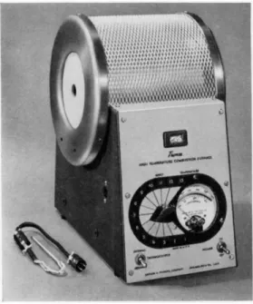
Suitable electric combustion apparatus are commercially a v a i l a b l e ,
1 6'
1 7 1 , 1 9 8such as those shown in Figs. 90, 124, and 125 (Chapter 9 ) , minus the heat
ing mortars (Chapter 9 ) shown in Figs. 124 and 125, which are required
Γ * ! -it A.
FIG. 89. Micro-D SCLUD.
for the carbon-hydrogen determination. The same type of apparatus (long and short furnaces) may be used for several of the combustion procedures described in the following chapters. The furnaces shown are mechanized and have wide ranges of operating temperatures making them suitable for the various com
bustion methods. Radiant heating is employed in the Sargent unit.
Recently, tentative spécifications for the combustion furnace have been adopted by the American Society for Testing Materials. They are as follows
4:
* Stanley No. 600 shields, Stanley, New Britain, Connecticut.
157 Apparatus
"COMBUSTION U N I T
The combustion unit shall consist of a long furnace, a sample furnace, a com
bustion tube, a combustion tube closure, and a connection tube.
(a) Long Furnace:
(1) The long furnace shall have a maximum overall length of 8 in. ( 2 0 3 mm.) with the wall thickness at the ends not to exceed m- ( 6 m m . ) . The heating well in the furnace shall accommodate combustion tubes up to 13 mm. outside diameter. Electric heating elements shall be easily replaceable. The furnace shall be mounted firmly on a substantial support.
FIG. 90. Thomas combustion furnace.
( 2 ) The furnace shall be capable of continuous operation at temperatures up to 800° C , as measured inside the combustion tube in the middle of the furnace. The temperature drop from the center to points 1 in. (25 mm.) and 1% in. (45 mm.) from either end shall not exceed 15 per cent and 7 per cent, respectively, based on the temperature in the middle of the furnace. Means shall be provided for varying the temperature.
(3) Provision shall be made for rapid cooling of the combustion tube between analyses.
The furnace shall be designed so that it may either be moved away from the tube or turned off and cooled rapidly. In the latter case, the time required for cooling and reheating to operating temperature shall not exceed 30 min.
( 4 ) The furnace shall be equipped with some device for continuous or provisional indication of the temperature at the middle of the furnace.
(b) Sample Furnace:
(1) The sample furnace shall have an overall length not less than iy2 in. (65 mm.) nor more than 4 in. ( 1 0 2 mm.) with wall thickness at the ends not to exceed % in.
( 6 m m . ) . The heating well in the furnace shall accommodate combustion tubes up to 13 mm. outside diameter. Electric heating elements shall be easily replaceable. The fur
nace shall be mounted firmly on a substantial support.
( 2 ) The furnace shall be capable of continuous operation at temperatures up to 800° C , as measured inside the combustion tube in the middle of the furnace. The temperature drop from the center to points % in. ( 1 9 mm.) from either end shall not exceed 17 per cent of the temperature in the middle of the furnace. Means shall be provided for varying the temperature.
( 3 ) Items ( 3 ) and (4) of Paragraph (a) also apply to the sample furnace.
(4) I f the furnace is moved mechanically, it shall travel a distance of 61/^ in. ( 1 5 9 mm.) min., with provision for manual setting at any point. Whether the furnace has only one or more than one speed of movement over this distance, the rates of travel shall be within the limits of % to % in. ( 3 to 16 mm.) per min. An automatic control shall be provided to stop the travel of the sample furnace when it reaches the long furnace."
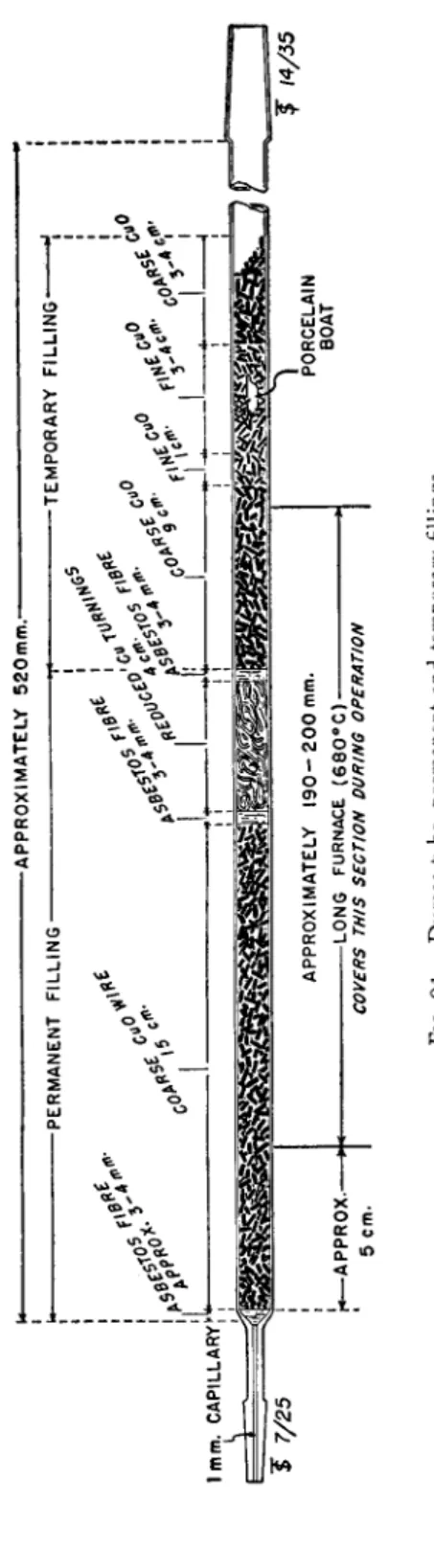
COMBUSTION TUBE
The combustion tube shown in Fig. 91 is prepared by sealing two male mem
bers of interchangeable ground joints to the ends of a piece of Pyrex 1 7 2 0 * glass tubing approximately 520 mm. in length, 11 mm. O.D., 8 mm. I . D . f To the one end is sealed a 7 / 2 5 joint and to the other a 1 4 / 3 5 member.{
The large end connects to the carbon dioxide generator while the small end is attached to the needle valve (see Fig. 9 2 ) . [Male joints are used on the combustion tube so that the cement used to hold the parts together (see below) does not enter the combustion tube.}
FILLING T H E COMBUSTION T U B E ( P E R M A N E N T F I L L I N G ) — F I G. 9 1 . Only
new tubes should be used. No attempt should be made to clean out the old filling from a tube and replace it with new material. With constant use a tube will usually give good results for at least one month. When good determinations are no longer obtained, the filling may be recovered but the tube should be discarded. Most tubes develop cracks or pinholes where the copper oxide fuses through, accounting for the failure. The filling is composed of two parts, the permanent and the temporary. The new tube, before filling, should be dusted with a cotton swab. Enough asbestos fibers (acid-washed) should be placed in the tube and pushed into place with a glass rod to form a plug of 3 - 4 mm.
in length. About a 15-cm. section of the coarse copper oxide wire is then added with tapping to cause the particles to pack solidly. Another asbestos plug of 3 - 4 mm. in length is added with the aid of the glass rod. Enough metallic copper turnings are added then with the aid of a glass ramrod to make a tightly packed section 4 cm. in length. Another asbestos plug 3 - 4 mm.
* Corning Glass Works, Corning, New York. Vycor (also Corning) or quartz may be used.
f For this tubing use combustion tube with the tip removed—see Fig. 9 8 . ΐ Compare references 56, 121, 122, 210.
-APPROXIMATELY 520mm.- -PERMANENT FILLING --TEMPORARY FILLING" ,L+ I Ji L HJ-*—Ι—*—Ι—* 1mm. CAPILLARYfy"
J 7/25
'r*— APPROX.- 5 cm.APPROXIMATELY 190-200 mm. -LONG FURNACE (680°C)- COVERS THIS SECTION DURING OPERATION PORCELAIN BOAT
J 14/35 FIG. 91. Dumas tube, permanent and temporary fillings.
159 Apparatus
in length is added. This comprises the permanent filling which remains in place for the life of the tube (Fig. 9 1 ) . A new temporary filling is added to the tube for each determination—see below under Procedure.
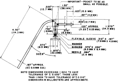
NEEDLE VALVE4 7 0 1 8 9 1 9 0
The all-metal needle v a l v e
4'
1 8 9'
1 9 0(Fig. 9 2 ) , is used to regulate the flow of gas through the train. A female member of a 7 / 2 5 interchangeable ground glass joint is attached to the horizontal portion on the right and a J 1 2 / l l /
2standard glass ball joint is attached to the downward slanting tube on the left.
; I M P O R T A N T - P O C K E T T O B E A S
N O T E : D I M E N S I O N S E X C E E D I N G I I N C H T O H A V E T O L E R A N C E O F 1 0 . 0 3 0 " . T H O S E L E S S T H A N I I N C H T O H A V E T O L E R A N C E O F ± 0 . 0 1 0 " . D I M E N S I O N S I N M I L L I M E T E R S A R E A P P R O X I M A T E .
FIG. 9 2 . All-metal needle valve—details of construction.
The glass and metal parts are connected by means of heavy-walled paraffin impregnated rubber tubing of 2-mm. bore using a trace of glycerin as a lubricant
(see chapter on carbon-hydrogen determination). The 7 / 2 5 joint connects to the smaller joint of the combustion tube while the ball joint fits the socket joint of the micronitrometer (see below). Gas passing through the combus
tion tube enters the valve through the horizontal capillary tube on the right, passes upward through the conoidal seat and then downward through the slanting tube on the left into the micronitrometer. The flow of gas through the valve is precisely regulated by turning the needle provided with a large knurled disk. The fittings are made gas-tight by means of a flexible sleeve, but a droplet of mercury is used at the point indicated as an additional pre
caution against leakage. The mercury is introduced through the horizontal
161 Apparatus
capillary. The valve must not leak with working pressures up to and including 10 pounds per square inch.
MICRONITROMETER (MICROAZOTOMETER)4^8^G5^ 121,122,139-141,158,163-166,186,190,212
The micronitrometer (Fig. 9 3 ) is the reservoir for collecting the nitrogen obtained during the combustion. It consists of ( a ) a downward slanting
S O L I D L E G S K 4 M M D I A .
A P P R O X .
f —6 5 ± 2 M M O . D .
I M P O R T A N T :
I.D. O F C A P I L L A R Y A T T H I S P O I N T T O B E 1 . 2M M A N D F L A R E S H O U L D B E S M A L L A S P O S S I B L E
I M P O R T A N T . ' T H E O.D. O F L O W E R I5MM L E N G T H S H O U L D N O T E X C E E D 1 9 . 5 MM
FIG. 93. Micronitrometer, Pregl-type, with leveling bulbs—details of construction.
capillary on the right through which the gas enters, ( b ) a reservoir to con
tain 5 0 % K O H for absorbing the carbon dioxide, ( c ) a leveling bulb* which
* Fig. 93 shows two types of leveling bulbs4>58,59,i39-i4i,i58,i63-i69,i86,i90_either may be used. The one at the top rests on the table during the determination while the bottom one must be held in an iron ring on the stand.
is connected with rubber tubing to a small side arm on the left and is used for raising and lowering the K O H , ( d ) a graduated portion for reading the volume of gas, ( e ) a stopcock and ( f ) a cylinder above the stopcock.
In the lower portion of the reservoir is placed enough mercury to be above the point where the downward slanting capillary on the right enters the reser
voir but below the small side arm on the left connected to the leveling bulb.
Gas entering the micronitrometer passes up through the mercury. In order to prevent gas bubbles from sticking to the mercury surface, a few milligrams of calomel ( H g2C l2)1 3 7 ) 1 5 7 , 1 8 6 are added.* T h e leveling bulb is then filled with a 5 0 % solution of pure K O H . [ T h e K O H is replaced about once a week, or sooner if the bubbles (see below) rise more than about 5 cm. before reducing in size.]
Connection to the needle valve is made by means of the ball and socket joint which is lubricated with Sisco No. 3 0 0 high-vacuum grease and the two parts of the joint are held together by means of a suitable clamp.f
The graduated portion of the tube has a capacity of 1.5 ml. and is divided into hundredths. Being a precision piece, calibration by the manufacturer is necessary and should be done according to the directions of the American Society for Testing Materials which are as f o l l o w s :4 , 8 1'1 3 3
"The volume contained by the nitrometer at 20° C shall be certified by the manu
facturer to the nearest 0.001 ml. at 6 points. The following procedure, in use by the National Bureau of Standards, is recommended.*
Calibrate the nitrometer, without the chamber, at the 0.1, 0.3, 0.5, 0.8, 1.1, and 1.5-ml. marks. After cleaning and drying, lubricate the stopcock with a minimum of petroleum jelly. Tare the instrument and mount it in the inverted position with the stopcock closed. Suspend a thermometer beside it and place a transparent screen around the assembly. Pour mercury into a small glass reservoir provided with a stopcock and having a long slender delivery tube. Insert the delivery tube into the tube of the nitrometer down to the stopcock for the initial filling at the 0.1.-ml. mark.
Carefully run in the mercury, raising the delivery stem as the filling progresses until the orifice is just above the surface. Fill nearly to the test mark, remove the stem, and by means of a long slender steel rod, probe around the filled portion of the nitrometer to work out air pockets. Insert the delivery stem nearly to the surface of the mercury and fill to slightly below the mark, agitate the tube to round the meniscus, and, if neces
sary, add or remove mercury to complete the setting on the line. Round the meniscus for every reading. After observing the temperature, allow the nitrometer to stand for about 3 min, check the setting and temperature, and, if these are satisfactory, weigh the nitrometer. Again clamp the nitrometer in position and, after standing for 5 min, insert the delivery stem, fill to the next test mark, and weigh the instrument as before. Follow the same procedure for the other points. Air pockets at the stopcock seem to be the main source of trouble.
* When the K O H is added, the calomel is converted to the oxide, f Arthur H. Thomas Company clamp, catalog No. 3241.
t See references 81 and 133.
163 Procedure
In general practice, the actual volume above 50 per cent potassium hydroxide solution in contact with glass walls is accepted as being 0.001 ml. less than that found by the mercury calibration, based on a determination by the Physikalisch-Technische Reichsanstalt."
Micronitrometers having stopcocks with Teflon* plugs are now commercially availablef and indications are that this type will become popular. Obviously, no lubricant should be used with these.
Procedure
Enough sample should be taken to obtain 0.3-0.4 ml. of nitrogen. I f the sample is either a solid or a high-boiling liquid, it should be weighed in a clean porcelain boat ( i f hygroscopic, with the aid of the weighing pig—see Chapter 3 ) . If the sample is a volatile liquid, it should be weighed in a capillary containing potassium chlorate—see Chapter 3.
TEMPORARY FILLING
To the combustion tube containing the permanent filling is added an approxi
mate 9-era. layer of coarse copper oxide followed by 1 cm. of fine copper oxide powder. The sample is then added (in the boat or capillary) to the combustion tube. Another 2 cm. of fine copper oxide powder is added and the combustion tube rotated with an occasional tilting so that the solid sample becomes mixed with the fine powder. Another 1-2 cm. of fine is added (with tapping) followed by several ( 3 - 4 ) cm. of coarse (see Fig. 9 1 ) . This com
pletes the temporary filling. (Note: If the sample is a pyrimidine, pyrazine, semicarbazide, or contains N-methyl groups or long aliphatic chains, 2 0 - 3 0 mg. of copper acetate and 1 0 - 2 0 mg. of potassium c h l o r a t e
1 2 0'
1 3 9'
1 4 0'
1 6 6'
1 8 1 , 1 8 6should be added to the sample in the boat before being placed in the com
bustion tube. If the sample is a sulfonamide or a nitrate it should be covered in the boat by about 50 mg. of powdered potassium dichromatej b u t ,
1 8 6in this case, the sample is not mixed with the copper oxide by rotating the tube as the dichromate must remain on the sample during the combustion to be effective. Even though the above-mentioned types are not being analyzed, if poor results are obtained and the apparatus is generally giving good results, either or both of the above modifications should be tried. If these fail, vanadium pentoxide should be mixed with the sample as this material has been used successfully with substances difficult to burn.
3 9)
* Ε. I. du Pont de Nemours & Co., Inc., Wilmington, Delaware.
f Kimble Glass Company, Vineland, New Jersey and Arthur H. Thomas Company, Philadelphia, Pennsylvania.
t Compare Furman,4 8 R o t h1 6 6 and G r a n t .5 8'5 9
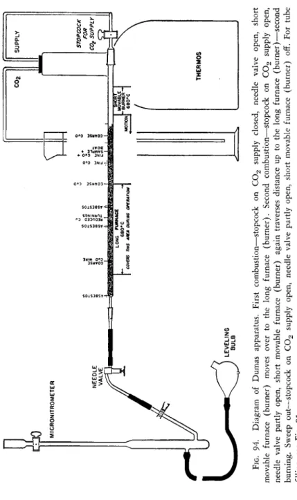
ASSEMBLING THE TRAIN (FIGS. 89, 97, AND 94)
The filled combustion tube is then placed in the cold combustion furnace (the 7 / 2 5 joint plus 5 cm. of the CuO filling extending beyond the long furnace) and attached to the carbon dioxide generator, using Kroenig glass cement as a sealing agent between the members of the ground joint. (The two members are warmed gently with a flame, a film of the wax applied to the male mem
ber, the parts joined, and held together until cool.*) The stopcock on the generator is opened and carbon dioxide is passed through the tube for about 5 minutes before the furnace is heated. This removes the air from the tube and prevents the oxidation of the metallic copper section. The long furnace is then heated to 6 7 0 ° - 6 8 0 ° C .
2 1 2(Avoid too high a temperature since the equilibrium between carbon dioxide and carbon monoxide is shifted toward the latter as the temperature is increased and a good grade of microbubbles will not be obtained—see Chapter 14.) During this time, the short movable sample furnace should be on the extreme right away from the long furnace.
(If the two furnaces were in contact the conduction of heat might be enough to decompose the sample before desired.) The stopcock on the generator is closed* and the combustion tube is now connected to the needle valve-micro- nitrometer combination using Kroenig glass cement as a sealing agent between the members of the ground joint (see above).f The stopcock at the top of the micronitrometer is opened then and the leveling bulb containing K O H is raised so that the solution fills the graduated tube and rises about halfway into the cylinder above the stopcock, after which the stopcock on the nitrometer is closed. ( K O H must be in the cylinder above the cock at all times or air might suck into the system at this point.)
THE SWEEP OUT
The leveling bulb is then placed on the table (or in a ring near the table top i f it is the conventional type). The needle valve is opened, the stopcock on the generator opened, and carbon dioxide allowed to sweep rapidly through until the bubbles in the micronitrometer become so-called "micro" in size.
These bubbles are obtained when all of the air has been replaced in the system and only carbon dioxide is coming through. Obviously, the size of the bubble will depend on the purity of the gas. For some generators and with fresh
* Otherwise the carbon dioxide pressure is apt to force a channel through the warm wax, giving a poor seal.
f When analyzing fluorine-containing compounds with a high percentage of that element, there is danger of clogging the capillary of the micronitrometer with deposited silica. This may be prevented by including in the setup a small bubble counter ( o f the type on the bubble counter-U-tube, Fig. 120, Chapter 9 ) which is filled with water. This is placed between the combustion tube and needle v a l v e .1 4 2
FIG. 94. Diagram of Dumas apparatus. First combustion—stopcock on C02 supply closed, needle valve open, short movable furnace (burner) moves over to the long furnace (burner). Second combustion—stopcock on C02 supply open, needle valve partly open, short movable furnace (burner) again traverses distance up to the long furnace (burner)—second burning. Sweep out—stopcock on C02 supply open, needle valve partly open, short movable furnace (burner) off. For tube filling, see Fig. 91.
165 Procedure
K O H in the micronitrometer, the bubbles will almost vanish while with others a much larger bubble will be obtained. However, bubbles are considered to be micro in size, and the gas suitable for use, if their diameter is less than the distance in the graduated tube representing 0.002 ml. (diameter = % distance between graduations of 0.01 m l . ) . I f the diameter of these bubbles is assumed to be approximately 0.2 mm. the volume of each bubble would be about 0.004 cu. mm. or 250 would represent a volume of approximately 0.001 ml. Bubbles coming through at the rate of one per second would repre
sent a total volume of about 0.014 ml. per h o u r .
1 5 8(Note: I f the generator has been giving a good grade of bubble and suddenly does not, the system should be checked for a leak in the following manner. After the bubbles no longer reduce in size, the stopcock on the carbon dioxide generator is closed and the system allowed to stand with the leveling bulb on the table top for 1 5 - 2 0 minutes. This keeps the system under reduced pressure and if a leak is present, air will suck in. The stopcock on the carbon dioxide generator is then opened and if a leak is present, fairly large bubbles will appear in the micronitrometer and a readable quantity of gas will appear in the graduated portion. I f there is no leak, the first few bubbles will be slightly larger, but then they will rapidly again reduce in size and no readable amount of gas will collect within several minutes.)
FIRST COMBUSTION
As soon as microbubbles are obtained, the leveling bulb is raised and the stopcock on the micronitrometer is opened to push out any gas present. The stopcock is then closed and the bulb returned to the table top. The stopcock on the carbon dioxide generator is then closed, the needle valve is opened a little more by turning the disc counterclockwise several turns, and the short furnace heated. When the temperature of the sample furnace is 6 7 0 ° - 6 8 0 ° C.
it is moved over towards the position in the tube near to the sample. This should be done with extreme care as too rapid a combustion leads to very high results.* As the sample begins to burn, bubbles will come through into the micronitrometer. Burning must be done slowly enough so that bubbles come through at a rate of one in 2 seconds or l e s s .
5 8'
5 9'
1 3 9'
1 4 0'
1 5 8'
1 6 3 1 6 6 , 1 8 6I f burning is continuing at the desired rate, the mechanical drive may be set into motion. The movable furnace is allowed to pass over the entire section of the tube outside of the long furnace. This operation is called the first com
bustion. When the movable furnace has traversed this distance it is then allowed to remain against the long furnace for several minutes. When the sample has been completely burned, a slight reduction in pressure will be
* Samples containing no nitrogen will give several tenths of a milliliter of gas if burned very rapidly.1 8 6
167 Procedure
noted in the tube as evidenced by the mercury rising in the capillary on the micronitrometer.
SECOND COMBUSTION
The needle valve should then be closed and the short movable furnace moved all of the way back to the right side of the tube. The hot furnace expands the cold gas in the end of the combustion tube and also volatilizes any water condensed in the right portion of the tube. This would cause a rapid flow of gas into the micronitrometer if the needle valve were not closed. The needle valve is slightly opened so that the expanded gas passes into the micronitrometer at the rate of one bubble per second. As soon as the bubbles cease passing through, the needle valve is momentarily closed, the stopcock on the carbon
α b
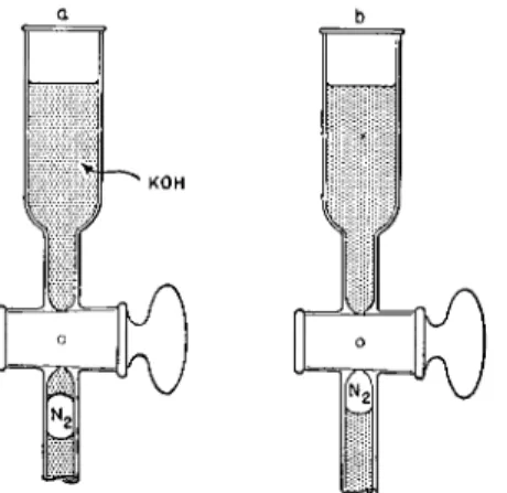
FIG. 95. Cleaning top of micronitrometer. ( a ) Small amount of K O H sucked into graduated portion during combustions, ( b ) Appearance after the K O H has been pushed out and N2 occupies its proper place for reading volume.
dioxide generator is opened and then the needle valve adjusted so that the rate into the micronitrometer continues as above. The hot movable furnace is passed along the tube at such a rate that about 10 minutes is required for it to traverse again the section of the tube up to the long furnace. This is known as the second combustion. It assures against any unburned material remaining. After the movable furnace has passed over the above distance, it is again pulled back to the far right end and allowed to cool. By this time, the bubbles coming through the micronitrometer begin to reduce in size consid
erably. By means of the needle valve, the rate of flow is increased next to two bubbles per second and finally to about five, as microbubbles are ap
proached.
1 5 8When microbubbles are obtained, the leveling bulb is raised to
a position above the cylinder at the top of the micronitrometer and, with the
magnifier, the portion of the graduated tube is examined. I f K O H has sucked
in the top above the gas (Fig. 9 5 a ) , it is completely pushed out into the
bore of the plug by carefully turning the stopcock (Fig. 9 5 b ) . (Caution:
Do not allow the gas to enter the stopcock bore or this will represent a loss.
If a bubble does enter the bore, it can be recovered by the following. The leveling bulb is lowered to the table top and the stopcock turned quickly so that the bubble plus a little K O H from the cylinder above the stopcock are pulled down into the graduated tube and then the stopcock is closed. The level
ing bulb is raised then above the cylinder and the stopcock carefully turned to push the liquid into the bore of the plug.) After standing at least 10 minutes, to insure drainage,
1 5 8the leveling bulb is lowered so that the surface of the liquid in the bulb and in the graduated tube stand at the same height (gas in the micronitrometer at atmospheric pressure) and the volume is read with the aid of the magnifier, estimating the thousandths of a milliliter. The temperature as recorded by a thermometer hanging next to the micronitrometer and at the level of the gas is noted, being read to the nearest half degree.* The atmospheric pressure in the room is recorded to the nearest half millimeter,*
using a mercurial barometer of the type shown in Fig. 96.
Calculation of Results
The volume of gas read in the graduated tube must have two corrections applied to it. First, the correction found on calibration by the manufacturer, as shown in the certificate furnished with all precision micronitrometers. The calibration is made at intervals of 0.1 ml. or more (see calibration of micro- nitrometers under Micronitrometer, above). All micronitrometers are calibrated with mercury in the inverted position. According to the accepted p r a c t i c e
4'
8 1 , 1 3 3diminishing these values by 0.001 ml. gives the calibration for 5 0 % K O H solution. Some manufacturers furnish a certificate merely showing the correct values at the several intervals over mercury, while others interpret the cor
rection for all points and include the 0.001 ml. deduction in the values. The two types of certificates encountered are shown in the following examples.
With the micronitrometer, one manufacturer might furnish certificate A, while another might furnish certificate Β (Table 1 7 ) .
The second correction for volume is one essentially due to the volume of K O H adhering to the walls of the tube and to the alteration in vapor tension.
For these, 2 % is deducted from the volume of gas after correction for the c a l i b r a t i o n .
5 8'
5 9'
1 5 8'
1 6 3 - 1 6 6'
1 8 6A temperature correction for the barometer must also be made.
7 2To reduce the readings of a mercurial barometer with a brass scale (type shown in Fig. 9 6 ) to 0 ° C , subtract 3 mm. from the reading at room temperature. The deduction is 3.0 mm. for only a very few combinations of temperature and pressure but
* Compare references 58, 59, 137, 139, 158, 163-166.
169 Calculation of Results
for most laboratory conditions the corrections range from 2 . 5 - 3 . 5 m m .7 2 and since the barometric pressure is only read to the nearest 0.5 mm., a flat de
duction of 3 mm. suffices. Where extreme laboratory conditions exist, the exact deduction should be used (see table in reference cited).
From the temperature, volume, and pressure, the results are calculated using the gas laws. T h e Nitrogen Reduction T a b l e1 3 9 , 1 4 0 given on pp. 5 7 4 - 5 8 3 ,
A:
T A B L E 17
CORRECTION T A B L E Interval
(ml.)
Contains (ml.) 0-0.1
0-0.3 0-0.5 0-0.8 0-1.1 0-1.5
0.100 0.300 0.496 0.797 1.097 1.497
(Calibrated with mercury in the inverted position. T o obtain the volume of gas over 5 0 % K O H solution deduct 0.001 ml.)
Β CORRECTION T A B L E — M I C R O P R E C I S I O N N I T R O M E T E R , PREGL
(Recommended Specifications A.C.S. 1 9 4 9 ) Contains at 2 0 ° C , K O H
Serial No. 114 Date of Certification January 14, 1950
ml.
0.00 0.01 0.02 0.03 0.04 0.05 0.06 0.07 0.08 0.09
ml. Corrected volumes in milliliters
0.0
— — — —
0.049 0.059 0.069 0.079 0.0890.1 0.099 0.109 0.119 0.129 0.139 0.149 0.159 0.169 0.179 0.189 0.2 0.199 0.209 0.219 0.229 0.239 0.249 0.259 0.269 0.279 0.289 0.3 0.299 0.309 0.319 0.329 0.339 0.349 0.359 0.369 0.379 0.389 0.4 0.399 0.409 0.418 0.428 0.438 0.447 0.457 0.466 0.476 0.485 0.5 0.495 0.505 0.515 0.525 0.535 0.545 0.555 0.565 0.575 0.585 0.6 0.595 0.605 0.615 0.625 0.635 0.645 0.655 0.665 0.675 0.685 0.7 0.695 0.705 0.715 0.725 0.735 0.746 0.756 0.766 0.776 0.786 0.8 0.796 0.806 0.816 0.826 0.836 0.846 0.856 0.866 0.876 0.886 0.9 0.896 0.906 0.916 0.926 0.936 0.946 0.956 0.966 0.976 0.986 1.0 0.996 1.006 1.016 1.026 1.036 1.046 1.056 1.066 1.076 1.086 1.1 1.096 1.106 1.116 1.126 1.136 1.146 1.156 1.166 1.176 1.186 1.2 1.196 1.206 1.216 1.226 1.236 1.246 1.256 1.266 1.276 1.286 1.3 1.296 1.306 1.316 1.326 1.336 1.346 1.356 1.366 1.376 1.386 1.4 1.396 1.406 1.416 1.426 1.436 1.446 1.456 1.466 1.476 1.486
Table 43, Chapter 23, is used in the calculation. One ml. of nitrogen at 0 ° C.
and 760 mm. of pressure weighs 1.2505 mg. The table gives the logarithm of the weight of one ml. of nitrogen at t° C. and p mm. The calculation is shown in the following example. Suppose that during a determination the micro-
FIG. 96. Barometer.
nitrometer whose calibration is shown by the two certificates A and Β (Table 17) is used. Also suppose the following:
Wt. sample 3.962 mg.
Vol. of N2 as read = 0.351 ml.
(not corrected) Temperature recorded
by thermometer near
micronitrometer = 23° C.
Barometric pressure in
laboratory = 761 mm.
171 Additional Information for Chapter 7
Calculation:
Vol. N2 read 0.351 ml.
Vol. correction for calibration —0.001 ml.
Vol. N2 corrected for calibration — 0.350 ml.
Minus 2 % (0.350 X 0.02 = 0.007) 0.007 ml.
Vol. of N2 corrected 0.343 ml.
Barometric pressure read
=
761 mm.Temperature correction —3
Corrected barometric pressure — 758 mm.
Log. wt. 1 ml. N2 at 758 mm. and 23° C. — 0.06076 (from Table 43, pp. 5 7 4 - 5 8 3 )
Plus log of corrected vol. of N0
(0.343 ml.) — 9.53529 — 10
Log. wt. of N2 obtained — 9.59605 — 10 Minus log. wt. sample ( 3 . 9 6 2 )
=
0.59791Log. fraction Ν — 8.99814 — 10
Plus log. 100
=
2.00000Log. % Ν — 10.99814 — 10
% Ν — 9.96
The allowable error of the method is dz 0 . 2 % ( ± 0 . 3 % for high per
centages of nitrogen).
ADDITIONAL INFORMATION FOR CHAPTER 7
The original micro-Dumas setup of P r e g l5 8-5 9-1 5 8'1 6 3-1 6 6 consisted of a Kipp generator similar to the type4 shown in Fig. 97, a combustion tube similar to that4 shown in Fig. 98, a three-way stopcock similar to t h a t4'1 9 0 shown in Fig. 99 but without the ball joint, and a micronitrometer (similar to that of Fig. 93 but without the socket j o i n t ) . (Note: The figures above referred to differ somewhat from those of P r e g l1 5 8 since they are those recommended by the Committee for the Standardization of Microchemical Apparatus1 9 0 of the Division of Analytical Chemistry of the American Chemical Society and Subcommittee 29 on Microchemical Apparatus under Committee E l on Methods of Testing of the American Society for Testing Materials.4) The various parts were connected by means of sections of heavy-walled rubber tubing impregnated with paraffin and by one rubber stopper (in the end of the combustion tube).
The combustion tube was heated by means of gas burners.
Niederl and N i e d e r l1 3 9'1 4 0 describe a setup using two Kipp generators
and a gasometer (Fig. 1 0 0 ) . The a u t h o r s
1 3 9-
1 4 0'
1 9 9'
2 0 0use a blank and a 1.1%
correction.
The author strongly advocates the use of interchangeable ground joints, although some workers still use rubber stoppers and rubber connectors. For those who so prefer, the American Society for Testing Materials
4tentative specifications include the connection tube (Z-tube) (Fig. 1 0 1 ) and the one-
1 5 2 ± 2 MM I.D.
/ B E A D
FIG. 97. Kipp generator (2000-ml. capacity)—details of construction.
hole rubber stopper,
4'
1 8 7(Fig. 153, Chapter 1 0 ) . Also for those who wish to use a combustion tube with side arm (Fig. 121, Chapter 9 ) , the above specifica
tions include the combustion tube with tip and side arm and the solid rubber stopper
4'
1 8 7(Fig. 165, Chapter 1 2 ) .
The mercury v a l v e
4'
7 1'
1 8 6'
1 9 0shown in Fig. 102 can be used to maintain the
desired pressure of carbon dioxide in the thermos flask and allows the excess
pressure to be released. It consists of a center tube which is placed in the hole
of a one-hole rubber stopper in the neck of the thermos flask. Connected to this
is the mercury reservoir containing a small head of mercury (about 2 . 5 - 5 c m . ) .
173 Additional Information for Chapter 7
E N D S Q U A R E D A N D G L A Z E D
5 2 0 5 3 0 M M . T O
U -1 1 . 2 5 M M . O . D .
± . 5 M M . 8 ± . 2 5 M M . I.D.
1.5 M M . M I N . W A L L
I I I
T O 3 0
3 5 M M . i h- 3 . 2 5 M M . O . D .
± . 2 5 M M . 1.5 T O 2 M M . I . D . E N D S Q U A R E D
A N D G L A Z E D
FIG. 9 8 . Standard Dumas combustion tube with tip—details of construction.
FIG. 99- Precision stopcock—details of construction.
A paper cap between the mercury column and the carbon dioxide generator acts as a bleeder for the excess pressure. T h e stopcock connects the flask to the combustion tube.
Besides the dry ice-filled thermos bottle as a source of carbon dioxide, Kipp generators (see above) charged with marble and hydrochloric acid are
u s e
d
1 1 , 1 2 , 5 8 , 5 9 , 1 2 1 , 1 2 2 , 1 3 7 - 1 3 9 , 1 5 8 , 1 6 3 - 1 6 6The marble must be specially treated but,
6512MM ,35±2MM,35t2MM, /FOR DETAILS SEE
PRECISION STOPCOCK EXCEPT OMIT LONG HANDLE
GLAZED Ι ΖΞ Ξ Γ 8±0.5MM O.D.
2.510.5MM I.D.
6 5 ± 2 M M 8 ±0.5 MM O.D.
GRADUATIONS ENTIRELY AROUND AND NUMBERED AS SHOWN ON BOTH SIDES
K-30+2MM0.D.
WALL I.5MM APPROX.
FIG. 100. Gasometer—details of construction.
in spite of this, air pockets down in the body of the pieces are released, in time causing contamination resulting in a poor grade of microbubbles.
Royer, Norton and F o s t e r
1 6 9and Aluise
3have used carbon dioxide from cylinders but this source is a rather uncertain one, some cylinders supplying an excellent grade of gas while from others the microbubbles are of a poor grade.
To eliminate this uncertainty, Gustin
6 3purified the gas by storing the
cylinder at — 7 0 ° C. overnight. T h e remaining pressure in the frozen cylinder
is quickly blown off to the atmosphere. This purge is repeated about four or
175 Additional Information for Chapter 7
five times about 5 minutes apart after the cylinder has been removed from the cold storage. The cylinder is then allowed to come to room temperature and is ready for use.
Pomatti
1 5 5introduced an iron wire into the micronitrometer which is floated on the mercury and moved over the surface by means of a magnet.
By this means, bubbles are prevented from adhering to the mercury surface.
GLAZED /
8 - 9 M M O.D.
WALL I MM APPROX.
5.5 - 6.5 MM O.D.
W A L L 2 MM APPROX.
FIG. 101. Connection tube (Z-tube)—details of construction.
To accomplish the same thing, Kirsten and Wallberg-Olausson
1 0 3added a trace of carbon disulfide to the potassium hydroxide to produce a mercury sulfide film. Finely divided copper o x i d e
5 8'
5 9'
1 3 9 , 1 4 0 , 1 6 6and a trace of amyl alcohol
1 5 7or mercurous o x i d e
1 3 7have also been used for this purpose. How
ever, in the author's opinion, the use of calomel (yielding mercurous oxide) described in this chapter, provides the simplest and most efficient means.
Barium hydroxide has been added to the potassium hydroxide to prevent
f o a m i n g .
5 8 , 5 9 , 1 5 8'
1 6 3 - 1 6 6The author finds, however, that this is not necessary
if reagent grade of potassium hydroxide is used. He has found that when certain
types of stopcock grease are used on the stopcock of the micronitrometer,
—I f—I712MMQ.D.
1GLAZED 1 FOR DETAILS SEE PRECISION STOPCOCK
EXCEPT OMIT LONG HANDLE
TOST? GLAZED
^ - 8 1 0 . 5 MM O.D.
I.5-2MM I.D.
FIG. 102. Mercury valve for carbon dioxide generator (pressure regulator) for use with dry ice—details of construction.
FIG. 103. Diagram of Gustin automatic modification. Combustion and absorption system. ( A ) Flow meter, 5 - 3 0 0 ml./min. flow range. ( B - l , B-2, and B - 3 ) Capillary stopcock, 2 mm. straight bore plug. ( C - l and C-2) Capillary stopcock, three way, 1 2 0 ° , 2 mm. bore plug. ( C - 3 ) Capillary stopcock, 2 mm. straight bore plug. ( D ) Synthetic rubber pressure tubing (neoprene), y± inch i.d., % inch o.d. ( E ) Combustion tube, 9 6 % silica, 7 mm. i.d., 9 mm. o.d. ( F - l and F-2) Sample furnace, movable split type, 2^ 2 - 3 inches long 1 2 - 1 3 mm. i.d. opening, at 850° C. ( F - 3 ) Heater, 4 inches long at 4 0 0 - 500° C. (micro C & H preheater type, A. H. Thomas Co., Philadelphia, Pennsylvania).
( G ) CuO wire, 2 0 - 6 0 mesh, ignited. ( H ) Pyrex glass-wool retainer. ( I ) Constant temperature tube, Pyrex, 8 mm. i.d., 10 mm. o.d., ca. 6 inches long. ( J ) Copper wire, 2 0 - 6 0 mesh. ( M ) Bar magnet, plastic covered, l/2 m cn long. ( N ) Absorption chamber, 36 mm. o.d., 6 inches high, 31/? inches to capillary column, side opening ca. 15 mm.
from base suitable for No. 2 rubber stopper. ( N A ) Capillary column, 2 mm. i.d., ca. 2 l /2
inches long, having a 1 mm. constriction in the column ca. 10 mm. long, reference line etched around mid-point of the constriction. § 1 2 / 2 socket joint top. ( N B ) Rigid side arm, 18 mm. o.d., top level with socket joint, 2 mm. i.d. capillary connection to absorp
tion chamber. ( R ) Natural rubber policeman, % inch i.d., τβ inch o.d., ca. 1 inch long, with 4 - 6 mm. slit cut in side, connected to capillary inlet, 2 mm. i.d. with J 1 2 / 2 socket joint. ( S ) Syringe, precision ground, 5 ml. capacity. ( V ) Direct reading counter, four digits, attached to syringe to show syringe displacement precisely to 0.001 ml.
177 Additional Information for Chapter 7
frothing is very bad—see Reagents. Niederl and N i e d e r l1 3 9-1 4 0 recommended heavy petroleum jelly and lanolin as a stopcock grease.
Instead of placing the sample in a porcelain b o a t ,2 5-4 8 weighed amounts of finely powdered substances have been placed in mixing tubes, fine copper oxide powder added, and the mixture transferred to the combustion tube using a dry w a s h .1 1'1 2'5 8'5 9'1 3 9-1 4 0-1 5 8-1 6 3-1 6 6 The author feels that this procedure is a
FIG. 104. Coleman nitrogen analyzer.
dangerous one, since materials that are slightly sticky or carry electrostatic charges cannot be always completely transferred.
A completely automatic combustion apparatus has been developed by G u s t i n6 1 - 6 3 (and now has become commercially available*3 0). Figures 103 and 104 show the diagram of Gustin's setup and a photograph of the commercial
* As this book goes to press the author has seen only a demonstration of the com
mercial u n i t3 0 and as yet one has not been delivered to his laboratory. Consequently, he can make no positive statement regarding these units.
model, respectively. Instead of the usual micronitrometer, a precision ground, 5 ml. capacity syringe is used in combination with a direct reading counter which makes it possible to read precisely to 0.001 ml. After the sample-packed combustion tube is attached, the automatic control is started. At the end of the cycle, the increased volume resulting from the combustion is read. W i t h this apparatus, Gustin completed six analyses per hour.
T A B L E 18
ADDITIONAL INFORMATION ON R E F E R E N C E S * RELATED TO C H A P T E R 7
Following the plan of previous chapters, additional information in the form of the listing of certain references is given in Table 18. (See statement at top of Table 4 of Chapter 1, regarding completeness of this material. ) f
General, miscellaneous Alford, 2
Belcher and Godbert, 11, 12 Belcher and Macdonald, 13 Buchanan, Grimes, Smith, and Hein-
rich, 19 Bussmann, 20 Clark, E . P., 25 Clark, H. S. and Rees, 26 Clark, S. J . , 27 Eder, 4 1
Etienne and Herrmann, 42 Fritz and Hammond, 4 6 Garch and Valdener, 50 Grant, 58, 59 Hozumi, 7 6 Ingram, 8 4 Iwasaki, 87, 88 Kainz, 89, 90 Kao and Woodland, 91 Kirsten, 9 3 - 1 0 1
Klimova and Dubinina, 106, 107 Ma, 116
Milton and Waters, 121, 122 Mitsui and Nishimura, 128
Murakami, Miyahara, and Nakai, 134 Murakami, 135
Niederl and Niederl, 1 3 9 - 1 4 0 Niederl and Sozzi, 141
General, miscellaneous (Conf.) Pagel and Oita, 150
Pregl, 158 Roth, 1 6 3 - 1 6 6
Royer, Alber et al., 167, 168 Rush, Cruikshank, and Rhodes, 170 Schenck, 172
Steyermark, 186 Vecefa and Snobl, 207 Collaborative studies
Ogg, 143-145
Steyermark, Alber, Aluise, Huffman, Kuck, Moran, and Willits, 191 Willits and Ogg, 2 1 4
Calculations
Belcher and Godbert, 11, 12 Clark, E. P., 25
Clark, S. J . , 27 Grant, 58, 59 Hozumi, 75
Niederl and Niederl, 139, 140 Pregl, 158
Roth, 1 6 3 - 1 6 6 Steyermark, 186 Trautz, 199
Trautz and Niederl, 200
* The numbers which appear after each entry in this table refer to the literature citations in the reference list at the end of the chapter.
f T h e large number of articles on the Dumas determination indicate that the deter
mination is by no means "perfect." T h e author also again wishes to emphasize that both the Dumas and Kjeldahl (Chapter 8 ) methods should be constantly used, the one as a check on the other.
179 Table of References
T A B L E 18 (Continued) Methods other than Dumas for deter
mination of nitrogen
(a) Kjeldahl—see Chapter 8 (b) Manometric—see Chapter 18 (c) Exchange resins, combination,
flame photometry, iodometric, colorimetric, magnesium ni
tride, hydrogénation, fusion, etc.
Banks, Cuthbertson, and Musgrave, 6 Batt, 7
Beauchene, Berneking, Schrenk, Mitchell, and Silker, 8
Brown and Musgrave, 18 Gel'man and Korshun, 5 1 - 5 3 Herbain, 68
Holowchak, Wear, and Bal- deschwieler, 73 Honma and Smith, 74 Ohashi, 146
Ohashi, Takayami, Taki, and Toya, 147 Polley, 154
Remy and Pitiot, 160 Renard and Deschamps, 161 Schôniger, 177
Takagi and Hayashi, 196 Weill and Bedekian, 209 Wust, 218
Ultramicro-, submicro methods Kirsten, 100
Simultaneous determination of nitrogen and other elements
Arthur, Annino, and Donahoo, 5 Berg and Gromakova, 14 Fedoseev and Ivashova, 44 Frazer, 45
Garch and Valdener, 50
Gel'man, Korshun, Chumachenko, and Larina, 54
Klimova and Anisimova, 104, 105 Schôniger, 173, 174, 178
Terent'ev, Fedoseev, and Ivasheva, 197 Wurzschmitt, 217
Analysis of fluoro-compounds Ma, 1 1 6
Analysis of nitrates Kieselbach, 92 Leithe, 114 Steyermark, 186
Analysis of nitro-compounds Genevois, 55
Steyermark, 186 Modifications
Abramson and Laurent, 1 Alford, 2
Arthur, Annino, and Donahoo, 5 Belcher and Bhatty, 10
Belcher and Macdonald, 13 Brancone and Fulmor, 15 Bussmann, 20
Charlton, 22
Childs, Meyers, Johnston, and Mitulski, 23
Clark and Dando, 28 Colson, 31, 32 Corliss, 33
Cropper, Reed, and Rothwell, 35 Dirscherl, Padowetz, and Wagner, 37 Dirscherl and Wagner, 38
Eder, 41
Fedoseev and Ignatenko, 43 Fukuda, 47
Gustin, 6 1- 6 3 Gysel, 64 Heron, 69
Hozumi and Amako, 77
Hozumi, Imaeda, and Kinoshita, 78 Hozumi and Kinoshita, 79, 80 Inada, 83
Ingram 84, 86 Kainz, 90 Kirsten, 9 3 - 1 0 1
Kirsten and Grunbaum, 102 Kono, 109
Mangeney, 117 Mitsui, 123-127 Mitsui and Tanaka, 129
T A B L E 18 (Continued) Modifications (Conf.)
Mizukami and Miyahara, 130
Mizukami, Miyahara and Numoto, 131 Narita and Ishii, 136
Otter, 148
Parks, Bastin, Agazzi, and Brooks, 152 Schôniger, 176
Shah, Pansare, and Mulay, 179 Shelberg, 180
Sternglanz, Thompson, and Savell, 184 Swift, 194
Swift and Morton, 195 Trutnovsky, 201 Unterzaucher, 202, 203 Vecefa, 205, 206 Vecefa and Synek, 208 Wolfgang and Grunbaum, 216 Zimmermann, 219
Various generators
British Standards Institution, 17 Childs and Moore, 24
Clark, E. P., 25
Dirscherl and Wagner, 38 Furter and Bussmann, 49 Hein, 67
Konovalov, 110 Pagel, 149
Parkin, Fernandez, Braun, and Rietz, 151 Poth, 156
Rauscher, 159 Schôniger, 175 Stock and Fill, 193 Kipp generators
Belcher and Godbert, 11, 12 Dirscherl and Wagner, 38 Grant, 58, 59
Milton and Waters, 121, 122 Nichols, 137
Niederl and Clegg, 138 Niederl and Niederl, 139, 140 Pregl, 158
Roth, 163-166
Pressure regulator for C 02 Di Pietro, Sassaman, and Merritt, 36
Marble used as source of C 02 Belcher and Godbert, 11, 12 Grant, 58, 59
Milton and Waters, 121, 122 Nichols, 137
Niederl and Niederl, 139, 140 Pregl, 158
Roth, 163-161
Salts other than marble used as source of C 02
Dubsky, 40 Govaert, 57 Ide, 82 Kuck, 112
Meixner and Krôcker, 118 Pagel, 149
Rauscher, 159 C 02 from cylinders
Aluise, 3 Gustin, 62, 63
Royer, Norton, and Foster, 169 Dry ice as source of C 02
Belcher and Godbert, 11, 12 Milton and Waters, 121, 122 Roth, 1 6 3- 1 6 6
Shelberg, 180 Steyermark, 186 Needle valves
Hershberg and Southworth, 70 Perrine, 153
Vango, 204 Nitrometers
British Standards Institution, 17 Clarke and Winans, 29 Cropper, 34
Guss, 60
Kirsten and Wallberg-Olausson, 103 Koch, Simonson, and Tashinian, 108 Kuck and Altieri, 113
Miller and Latimer, 119 Milner and Sherman, 120 Milton and Waters, 121, 122
181 References
T A B L E 18 Nitrometers (Conf.)
Mitsui, 127
Mitsui and Tanaka, 129 Mizukami and Miyahara, 130 Muller, 132
Pomatti, 155 Stehr, 182, 183 Willits and Ogg, 213 Wise and Roark, 215 Zimmermann, 219 Two micronitrometers
Hallett, 65 Kirsten, 93
Prevention of sticking of bubbles Grant, 58, 59
Kirsten and Wallberg-Olausson, 103 Nichols, 137
Niederl and Niederl, 139, 140 Pomatti, 155
Power, 157 Roth, 1 6 3 - 1 6 6 Steyermark, 186
Prevention of foaming of KOH Grant, 58, 59
Niederl and Niederl, 139, 140 Pregl, 158
Roth, 1 6 3 - 1 6 6 Steyermark, 186 Furnaces
Beazley, 9 Cannon, 21 Clark, E. P., 25 Clark, S. J . , 27
(Continued)
Furnaces (Con/.) Colson, 31 Corliss, 33
Cropper, Reed, and Rothwell, 35 Dirscherl and Wagner, 38 Hallett, 65
Ingram, 84, 85 Kirsten, 93
Korshun and Gel'man, 111 Levy and Mathieu, 115 Milton and Waters, 121, 122 Mitsui, 123, 125
Roth, 165
Royer, Norton, and Foster, 169 Steyermark, 185, 186
Zimmermann, 219
All glass apparatus (ground joints) Gonick, Tunnicliff, Peters, Lykken, and
Zahn, 56 Steyermark, 186 Weygand, 210
Small ground glass joints Stock and Fill, 192
Different methods of introducing sample
Belcher and Godbert, 11, 12 Clark, E. P., 25
Furman, 48 Grant, 58, 59 Kirsten, 93
Milton and Waters, 121, 122 Niederl and Niederl, 139, 140 Pregl, 158
Roth, 1 6 3 - 1 6 6
R E F E R E N C E S
1. Abramson, E., and Laurent, J . , Mikrochim. Acta, p. 786 ( 1 9 5 9 ) . 2. Alford, W . C , Anal. Chem., 24, 881 ( 1 9 5 2 ) .
3. Aluise, V . Α., Personal communication.
4. American Society for Testing Materials, AST M Designation, E 1 4 8 - 5 9 T ( 1 9 5 9 ) . 5. Arthur, P., Annino, R., and Donahoo, W . P., Anal. Chem., 29, 1852 ( 1 9 5 7 ) . 6. Banks, R . E., Cuthbertson, F., and Musgrave, W . K. R . , Anal. Chim. Acta, 13,
442 ( 1 9 5 5 ) .
7. Batt, W . G , / . Franklin Inst., 248, 451 ( 1 9 4 9 ) .