Accepted for publication in Fibers and Polymers Published in 2018
DOI: 10.1007/s12221-018-8183-2
A novel needleless electrospinning system using a moving conventional yarn as the spinneret
Hai-Jun Heb, Cheng-Kun Liua,d**, Kolos Molnarb, c
aSchool of Textile Science and Engineering, Xi'an Polytechnic University, Xi'an 710048, China
bDepartment of Polymer Engineering, Faculty of Mechanical Engineering, Budapest University of Technology and Economics, Műegyetem rkp. 3-9, H-1111 Budapest, Hungary
cMTA–BME Research Group for Composite Science and Technology, Műegyetem rkp.
3, H-1111 Budapest, Hungary
dThe School of Materials, The University of Manchester, Manchester M13 9PL, UK
ABSTRACT: A novel electrospinning system for the mass production of nanofibers
using a moving conventional yarn as the spinneret was designed. In the process of electrospinning, a large number of jets were ejected from the surface of the polymer liquid carried by the yarn. The effects of conductivity, surface structure and fineness of the yarn on the morphology and productivity of the obtained nanofibers were discussed in the research. Results indicate that the productivity of nanofibers can be
*Corresponding author, Tel.:+86-29-82330153.
E-mail address: fzlck@126.com; liuchengkun@xpu.edu.cn(C-K. Liu).
increased up to 1.17 g/h with our method, which is a at least fourfold enhancement compared to less than 0.3 g/h with the method of single-needle electrospinning. Both issues of needle clogging in needle electrospinning and intense solvent evaporation due to the open solution surface in most needleless electrospinning techniques can be avoided.
Keywords: needleless electrospinning; nanofiber; yarn spinnerets; productivity;
industrialization
1. Introduction
Nanofibers can be fabricated via electrospinning; they possess a huge specific surface area, a nano-sized diameter and high porosity [1, 2]. Therefore, they have great application potentials in wound dressings, tissue engineering scaffolds, protective clothing, electronics [3], sensors [4], drug delivery materials [5, 6], composites [7, 8], filters [9] and many other areas.
Traditional single-needle electrospinning is widely used to produce nanofibers in laboratories, but its productivity is only ≤ 0.3 g/h [10-12], which limits its industrial application. In order to increase the production of nanofibers, many methods have been proposed. The simplest way is to increase the number of capillary spinnerets [13-15]. However, several issues are still difficult to compensate for inmulti-needle electrospinning, including interference among the jets, needle clogging and washing.
Therefore, needleless electrospinning seems to be a more suitable and efficient way to produce nanofibers on a large scale. For example, Thoppey [16] reported a
high-throughput electrospinning method to produce nanofibers from a bowl edge.
Forward [17] utilized a wire electrode to entrain the fluid and jets ejected from the surface of the wire electrode at a high voltage. Qin [18] proposed a needleless electrospinning approach, with which multiple jets were formed on the edges of a stepped pyramid-shaped spinneret. Wang [19] mass-produced nanofibers by a strip-distributed solution delivery method. Liu [20] designed a needleless electrospinning method which uses a brush to cover the beaded wire electrode with the solution, from which numerous jets were generated. Recently, Liu [21] presented a technique using a needle-disk as the spinneret to enhance nanofiber throughput.
Molnár [22] introduced a modified electrospinning method which uses a thin circular gap bounded by a sharp edge to produce nanofibers, which might be a 20 - 50 times increase in productivity compared to that of the single-capillary method. Besides what mentioned above, an effective needleless electrospinning method called alternating current electrospinning was proposed [23-25]. In this method, a metal rod was used as the spinning-electrode to produce highly productive smoke-like aerogel composed nanofibers without any need of a grounded collector.
Lately, some electrospinning methods have been implemented in industrial practice.
One of the most popular technologies is Nanospider which was invented by Jirsák [26]
and manufactured by the Elmarco (Czech Republic) company. The second generation of this machine operates with a stationary wire electrode as the spinneret. A sliding carriage continuously covers the wire with the electrospinning solution, which leads to the formation of Taylor cones on the surface of the liquid. However, nanofiber
formation is often disturbed by the moving carriage itself, which can easily deform the droplets and Taylor cones on the surface of the wire and occasionally interrupt the spinning process. The carriage also shortens the working length of the wire spinnerets and creates an inhomogeneity in the electrostatic field. In this paper, we propose an alternative and optimized technique by using a moving conventional yarn as the spinneret to obtain multiple jets. The method can eliminate the above-mentioned issues of the Nanospider, as the solution supply is in a fixed position by using a stationary reservoir without the use of the carriage, while the yarn spinneret reciprocates in transverse direction to carry the spinning solution. Taylor cone formation is not disturbed, resulting in a truly continuous process. We investigated the effects of conductivity, surface structure and fineness of the yarn on fiber diameter and productivity. The productivity of the electrospinning prototype reached 1.17 g/h, which was much higher than that of conventional single-needle electrospinning, which was less than 0.3 g/h. This electrospinning technique can provide a more effective approach for scaling up nanofiber production and widening their applications.
2. Experimental
2.1 Materials
Polyacrylonitrile (PAN) (Mw=70000 g/mol, Hangzhou Bay Acrylic Fiber Co., Ltd, China) solutions with two different concentrations (8 wt% and 12 wt%) by dissolving the polymer in N,N-dimethylformamide (DMF) (Tianjin Kermel Chemical Reagents
Co., Ltd, China). DMF was used as received (without further purification).
2.2 Electrospinning set-up
The schematic figure of the novel needleless electrospinning system is shown in Fig. 1. The setup consists of five major components: a DC high-voltage power supply, a conventional yarn used as the spinneret, two sealed solution reservoirs to prevent solvent evaporation, two winding disks, and a cyclic collecting system. In this design, drop dripping in the spinning region can be avoided through control of thesolution quantity on the yarn spinneret and moving stability of the yarn spinneret. Diameters of the holes in the reservoirs are close to that of the passing yarn spinneret, so every hole acts like a wiper that can avoid taking too much polymer solution by the yarn into the spinning region. Also, the holes and the upper edges of the disks are not at the same height, which can provide a friction between the edge of the holes and yarn, and squeeze extra solution back to form a thin coating film on the surface of the yarn.In this experiment, several kinds of yarns (summarized in Table 1) were chosen to investigate the effect of yarn type on the spinning process.
Table 1
Fig. 1
2.3 Characterization techniques
The morphology of electrospun nanofibers was characterized with a field emission scanning electron microscope (FESEM; Quanta-450-FEG, FEI, England). The diameters of 100 nanofibers from the SEM images were measured with the Smile View software. Optical images and the motion trajectory of jets during the electrospinning process were recorded with a digital camera (HDR-SR11E, Sony, Japan) and a high-speed camera (Phantom v711, Vision Research Inc., USA), respectively. The mass of the collected nanofiber mat sample was measured with an electronic balance (Sartorius CP 225D, Germany) with the precision of 0.01 mg.
Finite element analysis (FEA) was carried out by Maxwell analysis software to get a detailed distribution of the electric field.
Nanofiber productivity could be obtained as follows: Firstly, three pieces of nonwoven collector (without nanofibers) with an area of 5×5 cm were weighed to obtain the average weight, which was used to calculate the areal density of the nonwoven collector (ρf). Then, the weight (Wt) and length (Lc) of the nonwoven collector coated by nanofiber membrane (spinning for 1 h) with a width of 20 cm were measured. Subsequently, the nanofiber productivity (P) can be calculated by the following equation (1):
f c
t L
W
P 20 (1)
where P is the nanofiber productivity [g/h]; Wt is the weight of nonwoven collector coated by nanofber membrane; Lc is the length of nonwoven collector [cm]; ρf is the
areal density of nonwoven collector [g/cm2].
3. Results and discussion
3.1 The mechanism of the novel electrospinning
During the electrospinning process, the cyclic collecting system is connected to high voltage, and the yarn spinneret is grounded. Two winding disks are rotated in the same direction driven by the motors, and the yarn wound on disk1 takes up the solution and passes through the electric field at a certain speed. When the yarn on winding disk1 is completely depleted, the two winding disks begin to rotate in reverse.
The whole length of the yarn used as the spinneret is approximately 500 mm for one rotation of the disc, which prevents the entanglement of the wet yarn loops when it is wound onto another disk. The real spinning length (i.e. the distance between the two reservoirs) of the yarn is 200 mm. Electrospinning voltage is increased until multiple jets are ejected from the surface of the yarn.
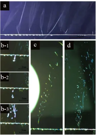
The electrospinning process can be divided into three steps: (i) solution feed: the rotation of the winding disks causes the yarn to take up the polymer solution and form a continuous film on the yarn, and then pass through the electric field; (ii) droplet formation: a number of droplets are continuously formed on the liquid film along the yarn because of Rayleigh instability; (iii) Taylor cone formation and jet initiation: jets emerge from the surface of the yarn when the force of the electric field overcomes surface tension (Fig. 2a). It was found that a jet could be formed when a droplet dropped and broke up as shown in Fig. 2b, or formed from a droplet (Fig. 2c), and
also from regions between two adjacent droplets (Fig. 2d). The projected area of the yarn spinneret is an important factor affecting nanofiber productivity, which can be further increased when multiple parallel yarns are used, as shown in Fig. 3.
Fig. 2
Fig. 3
3.2 The effect of traction speed of the yarn spinneret on the spinning process
During electrospinning, the traction speed of the yarn spinneret was set to 0.02 m/s, 0.04 m/s, and 0.06 m/s, while other conditions were fixed (20 kV, 8 wt%, 15 cm). As shown in Fig. 4, productivity at the traction speed of 0.04 m/s was increased by almost 50% compared to that at 0.02 m/s. However, productivity decreased when traction speed reached 0.06 m/s. It was also observed that the average spinning time of one droplet on the surface of G-SSCY was approximately 4.2 s before droplet depletion while the yarn travels the spinning length of 200 mm. Therefore, it can be calculated that the traction speed of 0.04 m/s is the optimal value for maximum
productivity. It may be explained as follows: for slower traction speeds, droplets on the yarn are depleted before reaching the other disk so there are no jets on the yarn for a period of time. By contrast, when traction speed is too high, the solution may have no time to form droplets and jets while it is passing through the spinning zone.
Therefore, the traction speed of the yarn can significantly affect droplet formation and spinning, and there is an optimal travel time for spinning.
Fig. 4
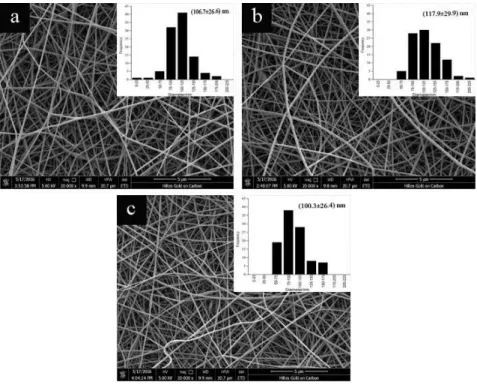
Besides productivity, the morphology and diameter distribution of fibers were also observed through SEM images (Fig. 5). Experimental results show that the diameters of nanofibers prepared at the three different traction speeds were 106.7 ± 26.6 nm, 117.9 ± 29.9 nm, and 100.3 ± 26.4 nm. Traction speed was found to have no significant effect on the diameter of fibers in the speed range we investigated. The phenomenon can be explained with the fact that nanofibers were generated by the combined effects of an electric field, surface tension, gravity and cohesive forces. The concentration of the solution, spinning voltage, spinning distance, etc. are the direct factors affecting the above-mentioned forces, hence these parameters can affect fiber diameter. It is assumed that traction speed is only a parameter that controls fiber production continuity, not the force acting on the jet in the electric field.
Fig. 5
3.3 The effect of yarn spinneret type on the spinning process
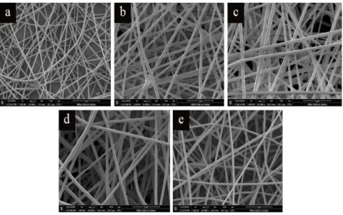
In the present work, the main aim was to investigate the effect of yarn spinneret type on nanofiber diameter and the productivity of the system. During electrospinning, all other spinning parameters were kept constant. A PAN/DMF concentration of 12 wt% was used as it produced better results that the liquid surface on the yarn was more homogeneous compared to that of the 8 wt% solution. A spinning voltage of 20 kV, a spinning distance of 150 mm and a yarn traction speed of 0.04 m/s were chosen, based on the results in part 3.2. Morphology, average diameter and productivity of nanofibers obtained with different kinds of yarn spinnerets are shown in Fig. 6 and Fig. 7. Finer fibers with narrower diameter distribution (198±29 nm) were produced from U-SSCY-40 compared to those (409±60 nm) produced from G-SSCY-40. The difference may be due to the shorter flight time resulting from the higher field intensity at the same collecting distance for the G-SSCY-40, leading to a smaller drawing ratio. However, the better conductivity of G-SSCY-40 results in a higher field intensity around the yarn and leads to a higher throughput (1.17 g/h). Nanofibers from G-SFY-40 had a smaller diameter than those from G-PFY-40, due to the rougher surface of G-SFY-40, leading to many non-uniform jets. On the other hand, the productivity of G-SFY-40 was higher than that of G-PFY-40, because the rougher surface of G-SFY-40 can take up more liquid and hence facilitate the formation of more Taylor cones and jets. The effect of the fineness of G-PFY on nanofiber
diameter and productivity is also shown in Fig. 7. Finer nanofibers and higher productivity were obtained from thicker G-PFY because of more liquid taken up and the formation of more Taylor cones. However, the process with the thicker yarn was not stable, because more jets ejecting from Taylor cones may interfere each other, and so nanofibers with a wider distribution of diameters were obtained.
Fig. 6
Fig. 7
The schematic of yarn surface structure is shown in Fig. 8. SFY is produced from short fibers by twisting, so there is a great deal of hairiness on the yarn surface. When the solution covers the surface of the yarn, a large number of irregular bulges are formed because of yarn hairiness and they help the formation of Taylor cones. In contrast, PFY is produced from multiple filaments, whose surface is relatively smooth and without twisting. It is indicated that the surface structure of the yarn is also an important factor influencing the formation of Taylor cones.
Fig. 8
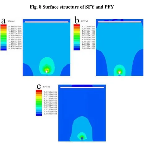
In order to investigate the effect of the conductivity of different yarn spinnerets on nanofiber diameter and productivity, finite element analysis (FEA) was carried out to compare electric fields around SSCY(conductive) and SFY(non-conductive). The upper part of the aluminum collector was charged to a high voltage and the yarn was either grounded or not. All the conditions (spinning distance, the linear density of the yarn, etc.) were set according to the above nanofiber production experiments.
Electric field distribution in the jet forming zone can affect the formation of Taylor cones. Fig. 9 represents the FEA results around the yarn spinnerets, where the electric field distribution was indicated. For the U-SSCY-40, the electric field intensity was so weak that it could not provide enough electric force to generate more jets leading to the low nanofiber productivity. In the case of G-SSCY-40, the higher electric field intensity was formed in the spinning region, and more jets could be generated on the surface of yarn spinneret with a result of a higher nanofiber productivity. Due to the lower conductivity of G-SFY-40 compared to that of G-SSCY-40, a weaker electric field intensity between the yarn spinneret and the collector was formed and led to a lower nanofiber productivity.
Fig. 9.
The results show that liquid take-up, wetting and the conductivity of the yarn
spinneret are the important parameters influencing fiber diameter and the productivity of the technique.
4. Conclusion
We designed a needleless electrospinning technique to produce nanofibers with a high throughput with a moving yarn (or yarns) as the spinneret(s). The idea was inspired by the Nanospider technology, but some of its drawbacks were eliminated. As opposed to most needleless technologies, here the solution reservoir is closed, therefore the evaporation of the volatile liquid can be avoided. Traction speed can significantly influence productivity and does not have an obvious correlation with the diameter and morphology of the obtained nanofibers. Yarn characteristics, including surface structure, conductivity, and fineness, have an effect on productivity, the morphology and diameter of the nanofibers. The number of Taylor cones and jets in the electrostatic field can be adjusted through the spinning length of the yarn between the two solution reservoirs. In the future, we plan to explore the effects of yarn speed, collector speed and the stability of the electrospinning process on the thickness uniformity of nanofiber membrane.
Acknowledgments
This work was supported by grants from the National Natural Science Foundation of China (51503168), the Shaanxi Innovation Talent Promotion Program-Project for Youth New Star of Science and Technology (2017KJXX-23), Special Funding for Postdoctoral Innovation Project in Shandong Province (201504), the China
Scholarship Council (201708610031), the National Research, Development and Innovation Office – NKFIH, OTKA PD 162211 & OTKA K116070, and ÚNKP-17-4-I New National Excellence Program of the Ministry of Human Capacities.
References
1. T. Subbiah, G. S. Bhat, R. W. Tock, S. Parameswaran and S. S. Ramkumar, J. Appl.
Polym. Sci., 96, 557 (2005).
2. E. D. Boland, G. E. Wnek, D. G. Simpson, K. J. Pawlowsk and G. L. Bowlin,J.
Macromol. Sci. Pure. Appl. Chem., 38A, 1231 (2001).
3. A. G. MacDiarmid, W. E. Jones, I. D. Norns, J. Gao, A. T. Johnson, N. J. Pinto, J.
Hone, B. Han, F. K. Ko, H. Okuzaki and M. Llaguno,Synth Met, 119, 27 (2001).
4. S. H. Lee, B. C. Ku and X. Wang, Mat. Res. Soc. Symp. Pro., 708, 403 (2002).
5. C. J. Buchko, L. C. Chen, Y. Shen and D. C. Martin, Polymer, 40, 7397 (1999).
6. E. Kenawy, G. L. Bowlin, K. Mansfield, D. G. Simpson and G. E. Wnek, Contr. J.
Release, 81, 57 (2002).
7. Y. Márquez, J. Graupera, L. J. del Valle, P. Turon, L. Franco and J. Puiggalí, EXPRESS Polymer Letters, 11(9), 674 (2017).
8. S. V. Lomov and K. Molnár, EXPRESS Polymer Letters, 10(1), 25 (2016).
9. T. C. Mokhena, V. Jacobs and A. S. Luyt, EXPRESS Polymer Letters, 11(8), 652
(2017).
10. J. S. Varabhas, G. G. Chase and D. H. Reneker, Polymer, 49, 4226 (2008).
11. A. K. Higham, C. Tang, A. M. Landry, M. C. Pridgeon, E. M. Lee, A. L. Andrady and S. A. Khan, American Institute of Chemical Engineers, 60, 1355 (2014).
12. H. Niu and T. Lin, Journal of Nanomaterials, 2012, 1 (2012).
13. S. Xie and Y. Zeng, Ind. Eng. Chem. Res., 51, 5336 (2012).
14. A. Kumar, M. Wei, C. Barry, J. Chen and J. Mead, Mater. Eng., 295,701 (2010).
15. A. Vaseashta, Appl. Phys. Lett., 90, 93 (2007).
16. N. M. Thoppey, J. R. Bochinski, L. I. Clarke and R. E.Gorga, Nanotechnology, 22, 1 (2011).
17. K. M. Forward and G. C. Rutledge, Chem. Eng. J., 183, 492 (2012).
18. G. J. Jiang, S. Zhang and X. H. Qin, Mater. Lett., 106, 56 (2013).
19. X. Wang, X. W. Hu, X. C. Qiu, X. Y. Huang, D. Z. Wu and D. H. Sun, Mater. Lett., 99, 21 (2013).
20. S. L. Liu, Y. Y. Huang, H. D. Zhang, B. Sun, J. C. Zhang and Y. Z. Long, Mater.
Res. Innovations, 18, 833 (2014).
21. Z. Liu, R. X. Chen and J. H. He, Mater. Design., 94, 496 (2016).
22. K. Molnar and Z. K. Nagy, Eur. Polym. J., 74, 279 (2016).
23. P. Pokorny, E. Kostakova, F. Sanetrnik, P. Mikes, J. Chvojka, T. Kalous, M. Bilek, K. Pejchar, J. Valtera and D. Lukas, Phys.Chem.Chem.Phys., 16, 26816 (2014).
24. A. Balogh, R. Cselkó, B. Démuth, G. Verreck, J. Mensch, G Marosi, and Z. K.
Nagy, International Journal of Pharmaceutics, 495, 75 (2015).
25. A. Balogh, B. Farkas, A. Domokos, A Farkas, B. Démuth, E. Borbás, B. Nagy, G Marosi, and Z. K. Nagy, European Polymer Journal, doi:
10.1016/j.eurpolymj.2017.08.032 (2017).
26. O. Jirsák, F. Sanetrnik, D. Lukas, V. Kotek, L. Martinova and J Chaloupek, U. S.
Patent, W02005024101 (2005).
Table 1. Summary of the yarn spinnerets (G: grounded, U: ungrounded) [tex=(m/L)*1000, m: weight of yarn [g]; L: length of yarn [m]]
Abbreviation Yarn type Linear density [tex]
U-SSCY-40 ungrounded stainless steel core-spun yarn 40 G-SSCY-40 grounded stainless steel core-spun yarn 40
G-SFY-40 grounded short cotton fiber yarn 40
G-PFY-40 grounded polyester filament yarn 40
G-PFY-65 grounded polyester filament yarn 65
Fig. 1 Schematic of the electrospinning set-up with a moving conventional yarn as the spinneret
Fig. 2 Jets formed during the electrospinning process: (a) photograph of multiple jets ejected from the yarn; (b-d) formation of jets in three different ways
Fig. 3 Schematic of multi-yarn electrospinning
Fig. 4 Productivity at different traction speeds
Fig. 5 Morphology and diameter distribution of nanofibers obtained at different traction speeds: (a) 0.02 m/s; (b) 0.04 m/s; (c) 0.06 m/s
Fig. 6 Morphology of electrospun nanofibers from different kinds of and differently charged yarns: (a) U-SSCY-40; (b) G-SSCY-40; (c) G-SFY-40; (d) G-PFY-40; (e) G-PFY-65 (scale bar
indicates 5 µm)
Fig. 7 Diameter and productivity of nanofibers from different yarns: A: U-SSCY-40, B:
G-SSCY-40, C: G-SFY-40, D: G-PFY-40, E: G-PFY-65
Fig. 8 Surface structure of SFY and PFY
Fig. 9 FEA of electrostatic field intensity around the yarn (the upper body is the collector with high voltage, and the lower is the spinneret): (a) U-SSCY-40; (b) G-SSCY-40;
(c) G-SFY-40
![Table 1. Summary of the yarn spinnerets (G: grounded, U: ungrounded) [tex=(m/L)*1000, m: weight of yarn [g]; L: length of yarn [m]]](https://thumb-eu.123doks.com/thumbv2/9dokorg/1398589.116948/18.892.158.717.153.635/table-summary-yarn-spinnerets-grounded-ungrounded-weight-length.webp)