Accepted for publication in Materials Today Communications Published in 2019
DOI: 10.1016/j.mtcomm.2019.100589
1
Electrospinning setup analogous to a cone-plate rheometer Kolos Molnár
1,2*1Budapest University of Technology and Economics, Faculty of Mechanical Engineering, Department of Polymer Engineering; Műegyetem rkp. 3, H-1111 Budapest, Hungary
2MTA–BME Research Group for Composite Science and Technology, Műegyetem rkp. 3, H- 1111 Budapest, Hungary
*molnar@pt.bme.hu
Abstract
We invented a novel electrospinning setup, which is analogous to a cone-plate rheometer in geometry. The setup allows the shearing of the solution in between the cone and the plate the same way the rheometer does, while with a continuous liquid support system the fibers are continuously emitted and collected in radial direction. We concluded that continuous shearing enhances Taylor-cone formation, which combined with the effect of acceleration, results in finer fibers. The average fiber diameter reduced from 227 to 87 nm because of the rotation. The setup opens new doors on a deeper understanding of the relations of the solution rheology and the fiber forming mechanisms.
Keywords: Fibre technology, Electron microscopy, Electrospinning, Nanofibers, Shear- thinning, Rheometry
How to cite:
Kolos Molnár, Electrospinning setup analogous to a cone-plate rheometer, Materials Today Communications, Volume 20, 2019, 100589, ISSN 2352-4928,
https://doi.org/10.1016/j.mtcomm.2019.100589.
2 1. Introduction
Electrospinning is a technology only widespread in research, since the industrialization of the process is hindered by the weak productivity of the ‘classical’ setup working with capillaries [1]. There are several needleless technologies [2,3] that make possible to generate nanofibers, but many issues still arise, such as: large open liquid surface [4-5] leading to evaporation and self-ignition of the volatile solvent or difficult cleaning and maintenance of the setup. In a previous work, we presented [6] that electrospinning can be efficiently implemented from a circular thin orifice and multiple jets can be launched at the same time. The method eliminates the problem of high open liquid surface and due to the closed system; therefore it can be used for related pharmaceutical and medical applications [7-9].
We recently have invented an electrospinning method [10] and this short communication presents our first results concerning a novel needleless electrospinning method, which operates with a long, circular orifice from which jets are emitted principally in radial direction. We recognized that the relative motion of the parts surrounding the orifice opens new possibilities in further increasing the throughput. With relative motion of the parts, a shear stress and shear deformation can be generated on the polymer solution just like at a cone-plate rheometer.
The rotating spinneret might remind the reader to the ForcespinningTM and other centrifugal spinning techniques [11,12], hence a clear distinction must be made. At centrifugal spinning techniques capillaries rotate at a high speed to generate centrifugal forces that help the fiber attenuation.
The current technique presented in this study is a needleless technology, since there is gap between the plates forming an orifice. Only the upper part of the spinneret rotates, while the bottom part is fixed like that at a rheometer. The electrospinning solution comes out of the orifice to make a film and the solution undergoes shearing due to the relative motion of the two plates. From the liquid, Taylor-cones are formed due to the electrostatic field. The jet formation is aided by the disturbances of the liquid caused by the rotation of the upper part.
In the experiments, we used polyethylene-oxide (PEO) – a shear thinning – solution [13] and rotation of the upper part took place in order to decrease the solution viscosity. Decreasing the viscosity by mechanical ways leads to high productivity and also to decreased fiber diameters.
2. Materials and methods
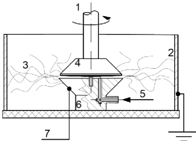
The scheme of the setup is shown in Figure 1. The spinneret consists of two, circular, sharp- edged electrodes (4 & 6), machined from aluminum, having a small gap between them, creating an orifice. Their distance can be set by lifting the upper part and/or placing washers between
3
them. The upper part is driven by a plastic shaft (1) in order to isolate the motor from the high voltage potential (7) wired to the stationary part. The rotating part has a small pin in the center to lead the upper and lower parts steadily together.
A syringe pump through a tube (5) supplies the solution that fills up the gap between the two main parts. The grounded collector (2) is a ring made of sheet metal and is concentric to the two main parts. The DC high voltage power supply (7) is connected to the fixed electrode (6), hence a radial high voltage electric field (3) is formed between the collector and the spinneret.
Figure 1. The scheme of the process. 1: drive, 2: grounded metal collector, 3: electrospinning space with forming nanofibers, 4: 2° cone electrode, 5: solution feed 6: plate electrode, 7:
high voltage connector
In the current study, the rotating part was a 2°cone with an outer diameter of 48 mm, while the stationary part was a plate (0°) with an outer diameter of 50 mm. The concentrically positioned collector’s diameter was 300 mm, therefore the distance between the spinneret edge and the collector was 125 mm.
Polyethylene oxide (PEO), obtained from Sigma-Aldrich (Mw = 400,000 g/mol) was dissolved in a 3:1 mixture of water:ethanol in the concentration of 4 wt% by stirring the material at room temperature overnight with a magnetic stirrer.
The viscosity of the solution was measured by a TA Instruments AR-2-type rheometer in a plate-plate arrangement, a setup quite similar to the spinneret. The rotating upper plate had a diameter of 40 mm, while the lower plate was temperature controlled and the gap distance was 600 µm. The viscosity was measured in step ramp mode at 20 °C in the shear rate range of 1 – 4,000 1/s with logarithmic sampling of 10 points per decade (at higher shear rates the sample splashed out).
4
The Carreau-Yasuda model [14] was fitted to the data points obtained then it was used to calculate the viscosity at arbitrary shear rates (𝜂(𝛾̇)). With the model, the viscosity can be calculated as (1):
𝜂(𝛾̇) = 𝜂∞+ (𝜂0− 𝜂∞)[1 + (𝜆𝛾̇)𝑎]1−𝑛𝑎 , (1) where η0 and η∞ are the viscosities at zero and at high shear rates, respectively, λ is the time constant, n is the power-law constant and a determines the transition between the low shear rate and the power-low sections.
In the experiments, we generated the rotation by a digital LCD overhead stirrer (Dragonlab OS- 20S pro) that allowed maintaining fixed set rotation speeds in 10-rpm increments. The rotation speeds were set to the following values: 0, 50, 200, 500, 1000, 1500 rpm. The gap distance between the fixed and the rotating parts was 0.9 mm, set by washers. An MA NT 75P, Hungary power supply, provided a DC voltage of 35 kV. An Aitecs-SP10S Plus type syringe pump fed the solution with a flow rate of 10 ml/h.
We set a Keyence VW-9000 type high-speed camera at 4000 fps to stare at the setup in order to observe how the jets evolve along the edges of the spinneret. JEOL JSM 6380LA type scanning electron microscope (SEM) was used to take images of the samples generated, after sputtering those with Au/Pd alloy. We determined the diameter of 100 fibers by image- processing software.
3. Results and discussion
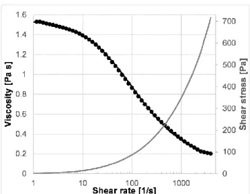
The measured viscosity and flow curve is depicted in Figure 2. The viscosity measurement points are indicated by dots, while the fitted Carreau-Yasuda model is a continuous black line.
The parameters of η0 = 1.55, η∞ = 0.10, λ = 0.0135, n = 0.335, a =0.89 gave a coefficient of determination of 0.9996. From this model, we calculated the viscosity for the selected rotation speeds that is presented later, in Table 1.
5
Figure 2. The result of the solution viscosity measurement with the fitted Carreau-Yasuda model
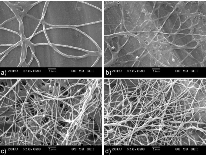
SEM images of the samples generated by the setup are shown in Figure 3. The non-rotating spinneret (a) generated an operation in which jets formed and then suddenly disappeared. At the same time the orifice was starving along the vast majority of the orifice length, while at some locations overflow occurred. Therefore, in this case we had to reduce the flow rate down to only 5 ml/h. Rotation helped to dispense the solution along the spinneret edge better that lead to a more even distribution of the jets along the spinneret with a flow rate of 10 ml/h. That is a 20-fold increase compared to the productivity of the single needle.
It is interesting to see that thick fibers were produced with the non-rotating spinneret. At slow speeds (Figure 3. b) the fibers became thinner, however some splashes also appeared besides the fibers as can be seen in the figure. Further increasing the speed at 500 rpm (Figure 3. c) a few beads appeared on the fibers indicating that the viscosity was slightly low. Above this rotation speed (Figure 5d presents 1500 rpm) the number of beads slightly increased but the fiber diameters did not change significantly.
6
Figure 3: Nanofibers generated from the PEO solution. a) 0 rpm (no rotation) 50 rpm c) 500 rpm d) 1500 rpm
The jets appeared at random positions along the orifice, but without a homogeneous distribution along the edge. At 50 rpm (b) the fiber formation became more stable and the solution is dispensed more homogeneously along the orifice edge. At higher rotation speeds (200 rpm and above) the operation became smooth; the jets became homogeneously distributed along the orifice.
High-speed camera images are shown in Figure 4. The four images were taken in a few milliseconds intervals, making a sequence from a) to d). The video recordings confirmed the homogeneous jet distribution along the spinneret edge; however, we note that some droplets stuck on the upper plate due to wetting forming Taylor-cones there. We believe that the surface roughness and the wetting of the electrodes are key factors in this phenomenon. The jets formed at the upper plate are moving together with that (Ma, Mb, Mc, Md), while the others are in a fixed position (Fa, Fb, Fc, Fd). One can see in the sequence of the pictures how the Mc double- jet goes from right to left or how the Md jet passes the screw (dark spot) of the baseplate.
7
These moving jets are further accelerated by the rotation, possibly leading to decrease in the diameter. This can be somewhat similar to centrifugal spinning, where the acceleration and the air friction further attenuates the fibers.
Figure 4. High speed camera images of the process taken at 200 rpm. The spinneret outer diameter is 50 mm.
We determined the average fiber diameters and their deviation from a set of SEM images and we summarized in Table 1 together with the viscosity values achieved in between the plates at the spinneret edge. Even though the non-rotating spinneret did not utilize the whole orifice for fiber spinning still it resulted in fine nanofibers with an average diameter of 227 nm. With the rotation speed applied, a continuous solution film formed along the orifice and more and more jets formed. Increasing the rotation speed also led to a gradual decrease in fiber diameter of more than 60 %.
Table 1. The nanofiber diameters as a function of the upper plate rotation speed rotation speed [rpm] 0 50 200 500 1000 1500
8
viscosity [Pa s] 1.55 0.78 0.44 0.30 0.23 0.20 mean diameter [nm] 227.2 144.4 115.1 94.04 89.4 87.2 deviation [nm] ±63.02 ±76.5 ±57.3 ±37.8 ±35.1 ±33.7
Figure 5. depicts the fiber diameters versus the virtual solution viscosity (a) and rotation speed (b) of the conical upper plate.
Figure 5. The fiber diameter as a function of the viscosity (a) and of the rotation speed
(b) (the non-rotating spinneret was depicted as 1 rpm for the representation in logarithmic scale)
In the case of the viscosity, the diameter is directly proportional to the fiber diameters. We can find a logarithmic relationship in between the rotation speed and the fiber diameters. The equation is burnt into the diagram (note: the non-rotating spinneret was depicted at 1 rpm). The coefficient of determination is 0.99 indicating a good quality fit.
The centripetal acceleration of the jets due to the rotation is proportional to the square of the rotation speed. No such direct trend can be fitted to the diameter versus rotation speed results.
It is important to see that the dependence of the shear rate and the viscosity is non-linear (i.e.
non-newtonian liquid) for the electrospinning PEO solution, still the viscosity – diameter relationship is clearly linear with a coefficient of determination of 0.997. That makes the viscosity as the main fiber morphology-controlling parameter. And the viscosity can be set by the shear rate even during the operation, like at a rheometer.
4. Conclusions
9
In this study, we demonstrated that from a spinneret, which is analogous to a cone-plate rheometer in terms of geometry and shearing conditions, electrospinning jets can be launched in radial direction. It is a needleless technology where the open solution surface is small, therefore volatile solvents can also be applied. The rotation of the upper, conical electrode generates shear stresses, leading to decrease of the viscosity of the polymer solution, which results in enhanced jet formation along the sharp edges of the spinneret parts. We successfully collected nanofibers on a circular grounded collector. The average diameter of the nanofibers decreased along with the rotation speed showing a logarithmic relationship in between them.
The viscosity versus nanofiber diameter relationship is clearly linear with a coefficient of determination of 0.997. Changing the rotation speed and manipulating the viscosity became a measure of fiber morphology, since we managed to set the diameter in between 227 nm down to 87 nm by simply adjusting the rotation speed of the motor.
Acknowledgements
This work was supported by the Higher Education Excellence Program of the Ministry of Human Capacities in the framework of the Nanotechnology research area of the Budapest University of Technology and Economics (BME FIKP-NANO). This research was also supported by the National Research, Development and Innovation Office (OTKA K116090).
References
1. Y. Liu, L. Zhang, X.-F. Sun, J. Liu, J. Fan, D.-W. Huang, Multi-jet electrospinning via auxiliary electrode, Mater. Lett. 141 (2015) 153–156.
https://doi.org/10.1016/j.matlet.2014.11.079.
2. P.K. Bhattacharjee, G.C. Rutledge, Electrospinning and polymer nanofibers: process fundamentals, in: P. Ducheyne (Ed.), Comprehensive Biomaterials II, Elsevier 2017, pp. 200–216. https://doi.org/10.1016/B978-0-08-100691-7.00165-8.
3. Kenry, C. T. Lim, Nanofiber technology: current status and emerging developments, Prog. Polym. Sci. 70 (2017) 1–17.
https://doi.org/10.1016/j.progpolymsci.2017.03.002.
4. M.B. Bazbouz, H. Liang, G. Tronci, A UV-cured nanofibrous membrane of
vinylbenzylated gelatin-poly(ɛ-caprolactone) dimethacrylate co-network by scalable free surface electrospinning, Mater. Sci. Eng. C. 91 (2018) 541–555.
https://doi.org/10.1016/j.msec.2018.05.076.
10
5. I. Shepa, E. Mudra, M. Vojtko, P. Tatarko, V. Girman, O. Milkovic, T. Sopcak, V.
Medvecka, J. Dusza: Preparation of highly crystalline titanium-based ceramic
microfibers from polymer precursor blend by needle-less electrospinning, Ceram. Int.
44 (2018) 17925–17934. https://doi.org/10.1016/j.ceramint.2018.06.268.
6. K. Molnar, Z.K. Nagy, Corona-electrospinning: needleless method for high- throughput continuous nanofiber production, Eur. Polym. J. 74 (2016) 279–286.
https://doi.org/10.1016/j.eurpolymj.2015.11.028
7. B. Démuth, A. Farkas, H. Pataki, A. Balogh, B. Szabó, E. Borbás, P.L. Sóti, T. Vigh, É. Kiserdei, B. Farkas, J. Mensch, G. Verreck, I. Van Assche, G. Marosi, Z.K. Nagy, Detailed stability investigation of amorphous solid dispersions prepared by single- needle and high speed electrospinning, Int. J. Pharm. 498, 1–2 (2016) 234–244.
https://doi.org/10.1016/j.ijpharm.2015.12.029.
8. C. Liu, J. Shen, C.Z. Liao, K.W.K. Yeung, S.C. Tjong, Novel electrospun
polyvinylidene fluoride-graphene oxide-silver nanocomposite membranes with protein and bacterial antifouling characteristics, Express Polym. Lett. 12 (2018) 365–382.
https://doi.org/10.3144/expresspolymlett.2018.31
9. V. Guarino, G. Ausanio, V. Iannotti, L. Ambrosio, L. Lanotte, Electrospun nanofiber tubes with elastomagnetic properties for biomedical use, Express Polym. Lett. 12 (2018) 318–329. https://doi.org/10.3144/expresspolymlett.2018.28
10. K. Molnár, G. Kaszás, High productivity shear-aided electrospinning apparatus and method thereof, US 62/765, 216 (2018).
11. K. Sarkar, C. Gomez, S. Zambrano, M. Ramirez, E. de Hoyos, H. Vasquez, K.
Lozano: Electrospinning to Forcespinning™, Mater. Tod., 13 (2010) 12–14.
https://doi.org/10.1016/S1369-7021(10)70199-1.
12. N. Obregon, V. Agubra, M. Pokhrel, H. Campos, D. Flores, D. De la Garza, et al., Effect of Polymer Concentration, Rotational Speed, and Solvent Mixture on Fiber Formation Using Forcespinning®, Fibers. 4 (2016) 20.
https://doi.org/10.3390/fib4020020
13. M. Pakravan, M.-C. Heuzey, A. Ajji: A fundamental study of chitosan/PEO electrospinning, Polymer. 52 (2011) 4813–4824.
https://doi.org/10.1016/j.polymer.2011.08.034.
14. J. Carreau, D. C. R. De Kee, R. P. Chhabra: Rheology of polymeric systems, principles and applications, Hanser/Gardner, Cincinnati, 1997.