1
Accepted for publication in Materials Research Express Published in 2019
DOI: 10.1088/2053-1591/ab11fd
Shear-aided annular needleless electrospinning Kolos Molnár
Budapest University of Technology and Economics, Faculty of Mechanical Engineering, Department of Polymer Engineering;
MTA–BME Research Group for Composite Science and Technology, Műegyetem rkp. 3, H-1111 Budapest, Hungary
molnar@pt.bme.hu Abstract
We briefly introduce a new approach for electrospinning in this paper. The novel high-speed electrospinning setup we invented involves a spinneret consisting of a cylindrical rotor placed within a concentric stator, both having a sharp metal edge. The solution gets out of the spinneret at the annular orifice in between these two edges forming a narrow liquid meniscus from which electrospinning jets are initiated. The setup applies mechanical shearing on the electrospinning solution. As the shear rate is increased (via the rotation speed) the viscosity of the shear-thinning solution decreases leading to enhanced Taylor-cone formation and the initiation of multiple jets. The throughput can be several orders of magnitude higher than that of the single capillary method and seems to be limited mainly by the evaporation rate of the solvent. With the small spinneret we reached 20 ml/h throughput for poly(ethyle oxide) solutions. The average fiber diameters decreased from 297 nm to 202 nm by applying shearing within the annulus.
Keywords: Needleless electrospinning, shear stress, rheology, industrialization, nanofibers
1. Introduction
Electrospinning is a popular method in research for generating nanofibers, since these can have applications in various sensor & engineering [1,2], biomedical [3-5] and pharmaceutical [6-8], etc.
fields. The industrial implementation of the nanofiber related applications is hindered by the meager productivity of the basic setup operating with a single capillary [9,10]. Increasing the number of capillaries [11] or using an auxiliary electrode [12] is feasible, but not innovative enough to overcome the general limitations (productivity issues, clogging of needles, beard formation, difficult cleaning, etc.) originating from the principle of the method [13]. The first needleless method was reported by Yarin and Zussman [14] in 2004. This method involves a two layer system: a magnetic fluid is
2
agitated by magnetic field which creates disturbances on the surface of the upper, polymer solution layer. In their study, poly(ethylene oxide) was used for the experiments. Later other upward needleless electrospinning methods were suggested by others. The most feasible one is developed at the Technical University of Liberec, in the Czech Republic [15] and widely known as NanospiderTM of the Elmarco company. Later other ideas were suggested to overcome the limitations of capillary electrospinning, in which most often an open liquid surface is applied and the jets are launched from this surface, with the aid of various agitation methods (gas bubbles, mechanical, electromagnetic, etc.) [16]. In 2013, Lin and Wang [17] summarized the needleless electrospinning techniques in their book, which includes most of these upward open surface methods.
The other group of needleless electrospinning techniques, a metal wire wetted by a thin layer of solution [18]. Another interesting recent development is the pyramid-shaped spinneret [19-20]. The large free liquid surface can be eliminated with a thin orifice combined with a sharp edge [19], which supplies the solution and launches the jets. Vysloužilová et al. [22] shown that coaxial electrospinning can also be implemented by needleless electrospinning based on a slit-type electrode.
In our method patented recently [23], we use a thin circular orifice for supporting the electrospinning polymer solution. High voltage is applied on the edge surrounding the orifice, causing local charge concentration, leading to enhanced electrospinning jet initiation. Moreover, the setup generates mechanical stresses on the solution, which also play an important role in jet initiation. Shearing decreases the viscosity of the shear-thinning electrospinning solution within the spinneret. The new setup has the following advantages compared to the classical set ups:
1. high throughput,
2. fiber diameter can be controlled via the rotation speed, even during operation, 3. no clogging during operation, no beard formation,
4. no high surface for solvent evaporation thus low boiling point or flammable solvents can be used, 5. homogeneous solution feed along the orifice, aided by a threaded distribution channel,
6. multiple, self-arranging Taylor-cones along the edge, 7. improved jet initiation,
8. a simple and easy-to-maintain spinneret.
In this study, we introduce the method itself and the first results we obtained with the novel setup.
We chose poly(ethylene oxide) for the experiments, since it has a broad literature [14, 24, 25]. There are many parameters, which affect the electrospinning process, and the morphology of the fibers, including solution concentration, solution conductivity, temperature, relative humidity, voltage,
3
collector distance [26-29] just to name a few. In this study we fixed all parameters and tested the effect of the shear conditions (i.e. rotation speed of the rotor) on fiber diameters and morphology.
2. The invented electrospinning process
The schematic drawing of the novel electrospinning setup can be seen in Figure 1. The most essential part of the setup is the spinneret (1) itself mounted on a non-conductive platform (10). The spinneret consists of two main units: the rotor (8), which fits into a stationary housing, i.e. stator (7). At the bottom a copper slide bushing (9) connects them, maintaining concentric position during the rotation.
At the top part, an annular orifice is formed between the rotor and the stator, this is where the electrospinning jets are initiated. Both the stator and the rotor have a sharp edge.
The stator is connected to the high voltage power supply (5). The solution is fed into the spinneret (6) in radial direction via a male tube connector. For the smooth operation, lubrication of the bottom slide bearing (9) is necessary, what is ensured by the viscous solution itself. To avoid leakage a lip seal (11) is installed at the bottom. In order to isolate the motor from the high voltage source, a plastic shaft (12) makes the connection between them.
Figure 1. The scheme of the novel electrospinning setup. 1: spinneret, 2: grounded collector, 3:
electrospinning space, 4: grounding, 5: high voltage cable, 6: solution feed, 7: stationary part, 8: threaded rotating part, 9: bushing, 10: base platform, 11: lip seal, 12: plastic drive shaft
4
During the operation the rotor part maintains a continuous angular velocity, while the solution is supplied. The machined thread of the rotor takes up the solution and evenly distributes it along the annular orifice. In between the stator and the rotor the solution undergoes shearing. The shearing leads to rheological changes within the electrospinning solution, e.g. shear-thinning that can be favorable for electrospinning. Moreover shearing leads to an even distribution of the solution along the orifice and it prevents the clogging phenomenon and beard formation.
When applying high voltage, the sharp edges result in charge concentration, taking place right where the liquid comes out of the orifice. Multiple Taylor-cones form along the edges, trying to keep a constant distance from the neigboring ones due to Coulombic-repulsion. Therefore, shearing has a role in forming and distributing the Taylor-cones along the orifice. Our hypothesis is that by shearing, the shear-thinning liquid’s decreased viscosity results in proportionally smaller resistance against deformation. Therefore it is easier for the electrostatic field to turn the liquid into cone shapes, i.e.
smaller forces are necessary to initiate the jets. Rotation can therefore improve the throughput of electrospinning and also influence the fiber quality. During the flight of the jets, the load (tension) and deformation (stretching) state is completely different, which preliminary shearing does not affect significantly. The fibers are collected on the surface of a metal plate collector (2) for the basic setup.
The shear rate can be set simply by adjusting the angular velocity of the rotor, or alternatively by changing the gap distance.
3. Materials and methods
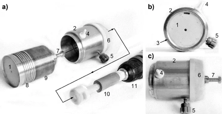
Figure 2 presents the spinneret used for the experiments. In the actual setup, the orifice had a 50 mm outer diameter with a gap size of 0.2 mm. A digital LCD overhead stirrer (IKA, RW 20 D S1) which allows to set the rotation speed and displays the value in rpm units, was driving the rotor. A plastic shaft with a diameter of 10 mm kept a 120 mm distance between the high voltage spinneret and the motor to simultaneously act as electrical insulator and to transfer the torque. Before putting the rotor and stator together, some polymer solution was manually applied on the inner surface of the stationary part. From then on, the polymer solution continuously lubricates the copper bushing.
The high voltage was supplied by a MA NT 75P (Hungary) direct current power supply. The solution was fed by an Aitecs-SP10S Plus type syringe pump with a rate of 20 ml/h. Five different rotational speeds were selected to investigate the effect of shearing on the fiber morphology and the operation of the setup. The rpm values were selected on the basis of the rheology experiment’s results (see chapter 4.1.).
5
Figure 2. The spinneret in a) exploded, b) top and c) side views. 1: rotor, 2: stator, 3: orifice, 4: solution inlet, 5: high voltage connector, 6: base, 7: hexagonal drive connection, 8: solution take-up thread, 9:
sliding bearing, 10: flexible plastic/rubber shaft, 11: chuck
For the experiments polyethylene oxide (PEO) (Mw=400.000 g/mol, Sigma-Aldrich) was dissolved in a mixture of water:ethanol of 3:1 in a concentration of 4.5 wt% at room temperature. PEO is not only water soluble, but easy to electrospun and is a polymer widely used in electrospinning literature [14,16,17] making it an ideal material for understanding the process.
The viscosity of the solution was determined by using TA instruments AR-G2 cone-plate rheometer in step ramp mode, in the rage of 0.1-5000 1/s at 25 °C. At higher shear rates the liquid splashed out limiting the applicable maximum shear rate in 5000 1/s. For the experiments a 2° cone with a diameter of 40 mm was used altogether with a controllable temperature lower plate. On the basis of the rheometry results the viscosity of the PEO solution was calculated for the various rpm-s we selected.
The morphology of the nanofibers obtained was investigated by a JEOL JSM 6380LA type scanning electron microscope (SEM) after slightly sputtering the samples with Au/Pd alloy. The diameter of 350 individual fibers were determined in case of each sample by ImageJ software. For each sample five different SEM images were chosen to take the possible structural inhomogeneity into account.
6 4. Results and discussion
4.1. Rheometry results
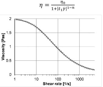
The result of the rheology experiments can be seen in Figure 3, indicated by dots. The solution had a zero viscosity of 2.0 Pa.s. The solution shows a clear shear-thinning (pseudoplastic) behavior, while the viscosity decreases a whole order of magnitude, down to 0.18 Pa.s. A Cross-Williamson model [30] was fitted onto the measured points as follows (1):
𝜂 =
𝜂01+|𝑡1𝛾̇|1−𝑛 (1)
Figure 3. The viscosity of the polymer solution used (dots) and the fitted Cross-Williamson model (continuous line).
The fitting resulted in an R2 value of 0.9985 with the parameters of 2, 0.045 and 0.46 for η0, t1 and n, respectively. We were able to calculate the viscosity for arbitrary rotation speeds (i.e. shear rates) by using this model.
The shear rate (𝛾̇) acting in between the stator and the rotor of the device can be calculated by the following formula (2):
𝛾̇(𝑟) =
𝑟𝜔ℎ (2)
where r [m] is the radius of the orifice, ω [rad/s] is the angular velocity of the rotor and h [m] is the gap distance of the orifice. For the current design, r = 0.025 [m] and h = 0.2 x 10⁻³ [m]. From the shear rate values obtained from (2), the viscosity values were calculated by (1). Shearing originating from material transport (slow solution feed in a direction perpendicular to the orifice) was neglected.
7
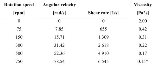
For the tests we selected 5 different rotation speeds and used steady rotor as the reference. The shear rates and viscosities are summarized in Table 1.
Table 1. The shear rate and viscosity for the tested rotation speeds.
Rotation speed [rpm]
Angular velocity
[rad/s] Shear rate [1/s]
Viscosity [Pa*s]
0 0 0 2.00
75 7.85 655 0.42
150 15.71 1 309 0.31
300 31.42 2 618 0.22
500 52.36 4 910 0.17
750 78.54 6 545 0.15*
*: extrapolated value from the Cross-Williamson model
It must be noted that shearing takes place when the liquid residues within the spinneret close to the outlet. Loads acting on the formed jets originate mainly from the electrostatic field, therefore shearing might not affect the stretching of the formed fiber jets. On the other hand, acceleration from rotation might rather play an important role in the jet thinning and on the fiber diameters. At high rotation speeds (300 rpm and above) the viscosity did not change significantly, making possible to investigate the possible effect of acceleration on the fiber morphology.
4.2. Operation
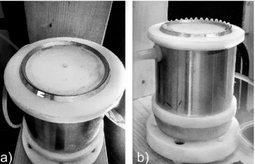
The assembled setup can be seen in Figure 4. The picture of Figure 4 b) was taken at 0 rpm. As one can see, close to the solution inlet the solution overflows onto the white plastic parts. When we apply rotation no such overflow can be observed at 20 ml/h. One can see the formation of multiple droplets from the meniscus of the liquid flowing out of the orifice, however the voltage was not high enough for jet initiation. The droplets arrange themselves in equal distances due to the repulsion of the charges carried on their surface.
8
Figure 4. The spinneret mounted to a wooden stand, a) the sharp edges and the annular orifice, b) Taylor-cone formation at 0 rpm
Besides preventing overflow, another important effect of rotation takes place at the jet initiation.
When increasing the voltage gradually, we observed continuous electrospinning at around 30 kV for the steady spinneret. The minimum voltage to initiate the jets is greater than that of the single needle electrospinning, but this phenomenon is typical for slit and other needleless methods [17] originating from the geometry and electric field of the spinneret. When applying rotation (150 rpm) the voltage to initiate the jets decreased to around 20 kV therefore we can conclude rotation favors jet initiation.
After the first experiments, we set the voltage to 35 kV to make sure we can generate the fibers at each and every rotation speed.
4.3. Morphology
Upon removing the samples (collected on an aluminum film substrate) from the collector, we visualized them. All the samples were thin veils, but at the reference sample of 0 rpm some thick jets were also visible by the naked eye. At 75 rpm some smaller, but still visible droplets were created besides the web. Figure 5. shows this phenomenon by presenting SEM images of the defects. The thick jet splashes (see an example in Figure 5. a)) had a thickness of more than 0.05 mm, while the droplets were in the range of several tens on micrometers. Besides these faults, proper nanofibers were produced.
9
Figure 5. The morphological defects of the samples collected at a) 0 rpm, b) 75 rpm
For the SEM experiments we tried to take the nanofiber samples from the same position on the collector screen in all cases. Images of the samples collected at various rpm-s can be seen in Figure 6.
For the steady spinneret the web contains relatively thick fibers, which are fused together in several occurrences. The fibers spun at 75 rpm also had thick diameters (as shown in Figure 6.), but multiple images taken revealed that thinner fibers also formed. By applying the rotation, not only the macro- sized faults disappeared, but the morphology of the fibers also changed significantly.
In general, one can see that the fiber diameters are decreasing that is assumedly happens due to the higher shear rates applied at electrospinning, however there was no big difference between the viscosity values above 300 rpm.
10
Figure 6. Fibers collected at different rotation speeds, a) 0 rpm, b) 75 rpm, c) 150 rpm, d) 300 rpm,
e) 500 rpm, f)750 rpm
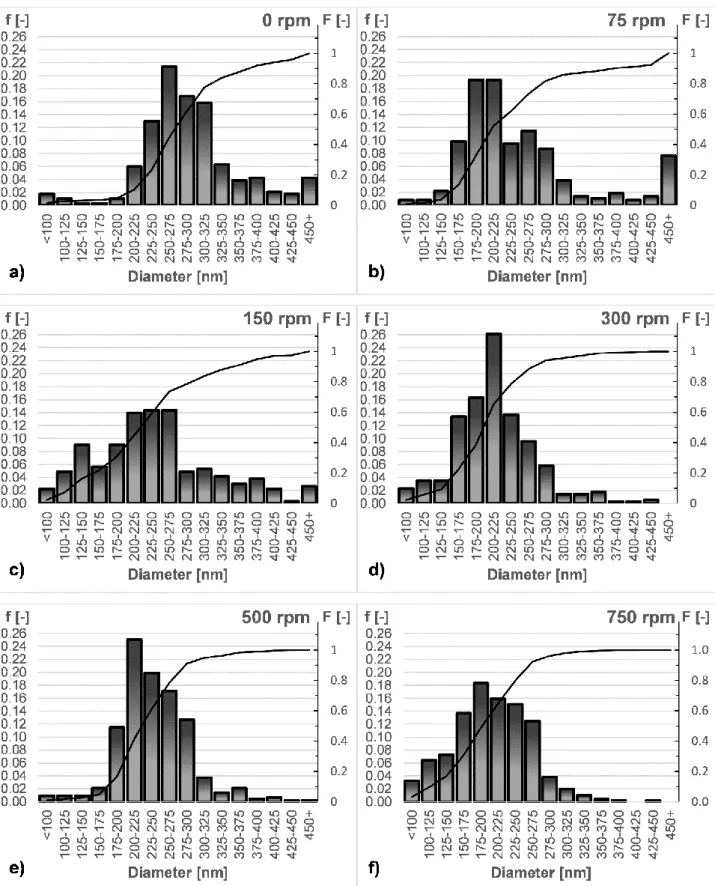
In order to understand how the rotation speed, i.e. the shear rate within the spinneret, influences the morphology we measured the fiber diameters by ImageJ software manually. As we observed inhomogeneity of the nanofiber samples, for each speciemen five different SEM images were investigated. From the results of the measurements, we generated fiber diameter histograms, which
11
are depicted in Figure 7. Besides the frequency bars presented in 25 nm increments, the cumulative distribution is also presented.
There was a range, in which the viscosity changed significantly: 0 rpm, 75 rpm and 150 rpm (call these „low rpm” samples). Above that, the change was no significant any further („high rpm”
samples).
When shearing is not applied the bar related to the highest frequency is at the 250-275 nm interval, which is gradually shifted to 200-225 nm for the high rpm samples. At the same time, no fibers were found above 450 nm diameter for the high rpm samples, which is not the case for the others. The (cumulative) diameter distribution (indicated with a continuous black line) also shows a difference between the low and high rpm samples, since the latter ones show a plateau above 300 nm.
The average fiber diameter decreased from 297 to 203 nm. In a former study of our research group [31] we studied the capillary electrospinning of the same PEO material. Depending on the needle diameter we reported an average diameter of 170-230 nm, which is in a good agreement with the values obtained with the current setup.
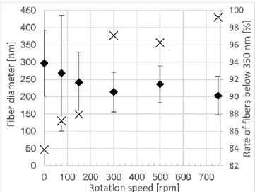
At the average fiber diameters diagram (Figure 8.) it can be seen that not only the average value decreases, but the distributions become narrower: the standard deviation decreases from more than a 100 nm to around 50 nm for the high rpm samples. This deviation can be considered small in electrospinning. Along with this phenomenon, the rate of fibers with a diameter below 350 nm diameter increases significantly by increasing the rotational speed (i.e. thick fibers disappear).
12
Figure 7. Fiber diameter histograms of the nanofibers electrospun at different rotational speeds
13
Figure 8. Average fiber diameters with standard deviation (♦) and the rate of faultless fibers with less than 350 nm diameter (X) as a function of rotation speed
5. Conclusions
In this study, we propose a completely novel approach for needleless electrospinning. We introduce a spinneret with an annular orifice, in which the center part is rotating. The electrospinning solution undergoes shear stresses due to rotation, which leads to the decrease in the viscosity within the spinneret. Viscosity-shear rate characteristics of the material play an important role in fiber formation and also temperature and time dependencies are key factors. The mechanism of the spinneret is simple: it only consists a few parts and the solution itself lubricates the bearing. A thread helps to disperse the solution homogeneously along the annular orifice.
The gap distance of the orifice and the rotation speed together determine the shear conditions. There are multiple other factors affecting the operation (vibration, temperature, surface roughness etc.), from which we limited the study only to the shear conditions via changing the rotational speed, while keeping all the others constant.
During the experiments it turned out that as result of the rotation no beard formation takes place along the orifice and shearing it helps to prevent clogging. We reached high throughputs (20 ml/h was tested) compared to single needle electrospinning with the small setup. As a result of shearing the decreased viscosity (characterized by rheometry) leads to smaller forces and voltage necessary to initiate the electrospinning jets. The experiments also revealed that shearing improves the morphology of nanofiber webs, since at 150 rpm and above the droplets and fiber-like splashes disappeared from the samples.
A detailed analysis of the fiber diameters was carried out on 350 fibers for each sample. The results showed that by applying rotation the fiber morphology improves and the diameters decrease. By the
14
rotation the thicker fibers disappear and a smaller deviation of fibers take place meaning better structural homogeneity. The average fiber diameter decreased from 300 nm to 200 nm by the applied rotation.
Acknowledgement
This work was supported by the Higher Education Excellence Program of the Ministry of Human Capacities in the framework of the Nanotechnology research area of the Budapest University of Technology and Economics (BME FIKP-NANO). This research was also supported by the Hungarian Research Fund (OTKA K100949, PD116122) and by the ÚNKP-17-4-I New National Excellence Program of the Ministry of Human Capacities and BME-KKP
References
1. Y.-K. Fuh, S.-Ch. Li, Ch.-Y. Chen, Ch.-Y. Tsai: A fully packaged self-powered sensor based on near-field electrospun arrays of poly(vinylidene fluoride) nano/micro fibers, Express Polymer Letters, 12(2), 136-145 (2018).
10.3144/expresspolymlett.2018.12
2. A. Sharifi, S. N. Khorasani, S. Borhani, R. E. Neisiany: Alumina reinforced nanofibers used for exceeding improvement in mechanical properties of the laminated carbon/epoxy composite, Theoretical and Applied Fracture Mechanics, 96, 193-201 (2018).
10.1016/j.tafmec.2018.05.001.
3. V. Guarino, G. Ausanio, V. Iannotti, L. Ambrosio, L. Lanotte: Electrospun nanofiber tubes with elastomagnetic properties for biomedical use, Express Polymer Letters, 12(4), 318-329 (2018).
10.3144/expresspolymlett.2018.28
4. C. Liu, J. Shen, C. Z. Liao, K. W. K. Yeung, S. C. Tjong: Novel electrospun polyvinylidene fluoride-graphene oxide-silver nanocomposite membranes with protein and bacterial antifouling characteristics, Express Polymer Letters, 12(4), 365-382 (2018).
10.3144/expresspolymlett.2018.31
5. N. Patra, L. Martinová, M. Stuchlik, M. Černík: Structure–property relationships in Sterculia urens/polyvinyl alcohol electrospun composite nanofibres. Carbohydrate Polymers, 120, 69–
73 (2015).
10.1016/j.carbpol.2014.12.002
15
6. Z. K. Nagy, A. Balogh, G. Drávavölgyi, J. Ferguson, H. Pataki, B., G. Marosi: Solvent‐free melt electrospinning for preparation of fast dissolving drug delivery system and comparison with solvent‐based electrospun and melt extruded systems, Journal of Pharmaceutical Sciences, 102(2), 508-517 (2013).
10.1002/jps.23374
7. C. J. Wang, T. C. Chen, J. H. Lin, P. R. Huang, H. J. Tsai, C. S. Chen: One-step preparation of hydrophilic carbon nanofiber containing magnetic Ni nanoparticles materials and their application in drug delivery, Journal of Colloid and Interface Science, 440, 179-188 (2015).
10.1016/j.jcis.2014.10.073
8. B. Démuth, A. Farkas, H. Pataki, A. Balogh, B. Szabó, E. Borbás, P. L. Sóti, T. Vigh, É.
Kiserdei, B. Farkas, J. Mensch, G. Verreck, I. Van Assche, G. Marosi, Z. K. Nagy: Detailed stability investigation of amorphous solid dispersions prepared by single-needle and high speed electrospinning, International Journal of Pharmaceutics, 498(1-2), 234-244 (2016).
10.1016/j.ijpharm.2015.12.029
9. D. Deshawar, P. Chokshi: Stability analysis of an electrospinning jet of polymeric fluids, Polymer, 131, 34-49 (2017).
10.1016/j.polymer.2017.10.019.
10. E.V. Solomin, E.A. Sirotkin, A.A. Sirotkin: Universal Electrospinning Scalable Plant for Filtering Nanofiber Production, Procedia Engineering, 206, 1371-1375 (2017).
10.1016/j.proeng.2017.10.647.
11. A.Varesano, R. A. Carletto, G. Mazzuchetti: Experimental investigations on the multi-jet electrospinning process, Journal of Materials Processing Technology, 209 (11), 5178-5185 10.1016/j.jmatprotec.2009.03.003.
12. Y. Liu, L.Zhang, X.-F. Sun, J. Liu, J. Fan, D.-W. Huang: Multi-jet electrospinning via auxiliary electrode, Materials Letters, 141, 153-156 (2015).
10.1016/j.matlet.2014.11.079.
13. R. Augustine, N. Kalarikkal, S. Thomas: Clogging-free electrospinning of polycaprolactone using acetic acid/acetone mixture, Polymer-Plastics Technology and Engineering 55(5) 518- 529 (2016).
10.1080/03602559.2015.1036451
14. A.L. Yarin and E. Zussman: Upward needleless electrospinning of multiple nanofibers, Polymer, 45, 2977-2980 (2004).
10.1016/j.polymer.2004.02.066
16
15. O. Jirsák, F. Sanetrnik, D. Lukas, V. Kotek, L. Martinova, J Chaloupek: A method of nanofibers production from a polymer solution using electrostatic spinning and a device for carrying out the method. Patent W02005024101 (2005).
16. B. H. Niu, X.Wang, T. Lin: Needleless Electrospinning: Developments and Performances, in:
Nanofibers – Production, Properties and Functional Applications, Ed: Tong Lin, IntechOpen Limited, London, UK (2011).
17. T. Lin and X. Wang: Needleless Electrospinning of Nanofibers, Technology and Applications. CRC Press – Taylor& Francis Group, Boca Raton (2013).
18. I. Bhattacharyya, M. C. Molaro, R. D. Braatz, G. C. Rutledge: Free surface electrospinning of aqueous polymer solutions from a wire electrode, Chemical Engineering Journal, 289, 203- 211 (2016).
10.1016/j.cej.2015.12.067.
19. G. Jiang, S. Zhang, X. Qin: High throughput of quality nanofibers via one stepped pyramid- shaped spinneret, Materials Letters, 106 56-58 (2013).
doi.org/10.1016/j.matlet.2013.04.084
20. G. Jiang, S. Zhang, Y. Wang, X. Qin: An improved free surface electrospinning with micro- bubble solution system for massive production of nanofibers, Materials Letters, 144, 22-25 (2015).
10.1016/j.matlet.2014.12.139.
21. K. Molnar, Z. K. Nagy: Corona-electrospinning: Needleless method for high-throughput continuous nanofiber production, European Polymer Journal, 74, 279-286, (2016).
10.1016/j.eurpolymj.2015.11.028.
22. L. Vysloužilová, M. Buzgo, P. Pokorný, J. Chvojka, A. Míčková, M. Rampichová, J. Kula, K. Pejchar, M. Bílek, D. Lukáš, E. Amler: Needleless coaxial electrospinning: A novel approach to mass production of coaxial nanofibers, International Journal of Pharmaceutics, 516, (1–2), 293-300 (2017).
10.1016/j.ijpharm.2016.11.034.
23. K. Molnár, G. Kaszás: High productivity shear-aided electrospinning apparatus and method thereof. US patent application, US 62/765,216 (2018).
24. T. Grothe, C. Großerhode, T. Hauser, P. Kern, K. Stute, A. Ehrmann: Needleless electrospinning of PEO nanofiber mats. Advances in Engineering Research (AER), 102, 54- 58 (2017).
17
25. Tripatanasuwan S., Zhong Z., Reneker D.H.: Effect of evaporation and solidification of the charged jet in electrospinning of Poly(ethyleneoxide) aqueous solution. Polymer, 48, 5742- 5746 (2007).
26. Yarin A. L., Kataphinan W., Reneker D.H.: Branching in electrospinning nanofibers. Journal of Applied Physics, 98, 064501 (2005).
27. Andrady A. L.: Science and technology of polymer nanofibers. John Wiley & Sons, Inc., New Jersey (2008).
28. Heikkilä P., Harlin A.: Parameter study of electrospinning of polyamide-6, European Polymer Journal, 44, 3067–3079 (2008).
29. Beachley V., Wen X.: Effect of Electrospinning parameters on the nanofiber diameter and length, Materials Science and Engineering C, 29, 663-668 (2009).
30. J. Carreau, D. C. R. De Kee, R. P. Chhabra: Rheology of polymeric systems, principles and applications, Hanser/Gardner, Cincinnati, 1997.
31. Haijun He, Yahya Kara, Kolos Molnar: Effect of Needle Characteristic on Fibrous PEO Produced by Electrospinning, Resolution & Discovery, online first, pp. 1-5.
10.1556/2051.2018.00063