Accepted for publication in Macromolecular Materials and Engineering
Published in 2019
DOI: 10.1002/mame.201900349
1
In situ viscosity-controlled electrospinning with a low threshold voltage
Haijun He1, Yahya Kara1, Kolos Molnár1,2*
1Budapest University of Technology and Economics, Faculty of Mechanical Engineering, Department of Polymer Engineering
2MTA–BME Research Group for Composite Science and Technology, Műegyetem rkp. 3., H- 1111 Budapest, Hungary
*corresponding author: molnar@pt.bme.hu
Abstract
Needleless high-speed electrospinning methods seem to be currently the most feasible techniques for large scale polymer nanofiber production. A popular type of needleless methods is slit-electrospinning, in which the polymer solution is pumped through a narrow and long slit, from which the jets are initiated. In our study, we propose a novel electrospinning method, where the jet formation is aided by shearing the solution in situ. Using a general polymer solution the viscosity decreases by shearing, i.e. the solution is shear-thinning. The setup also has small free surface of the solution, minimizing solvent evaporation. We used poly (ethylene-oxide) (PEO) as a model polymer and investigated the effects of rotation speed, solution concentration and gap size (the width of the annular orifice) on the process and the morphology of the obtained fibers. It is found that the threshold voltage for generating multiple jets decreased to 12 kV from 35 kV when rotation speed was higher than 60 rpm. Additionally, the results showed that fiber diameters increased as the solution concentration increased. Chi-square two-sample test was applied to compare the fiber diameter distribution from the capillary and the novel electrospinning process. In our method. the solution viscosity can be changed by mechanical ways during the electrospinning process, which results in electrospinning jet initiation at a low threshold voltage. We also found that the gap size has a similar effect on the fiber diameter as the needle diameter for classical electrospinning.
Keywords: Needleless electrospinning, Nanofibers, Morphology, Shear-aided electrospinning, Viscosity
How to cite:
He, Haijun; Kara, Yahya; Molnár, Kolos: In Situ Viscosity-Controlled Electrospinning with a Low Threshold Voltage. Macromolecular Materials and Engineering, 1900349, 304:11, (2019). doi:10.1002/mame.201900349
2 1. Introduction
Electrospinning has been attracting much attention since the detailed investigations on different polymer materials and process parameters were conducted by Reneker’s group in the early 1990s [1]. It is judiciously considered as a feasible technology to produce polymer nanofibers with nano-size diameter due to the related cost-effective and simple setup. The technology also provides a broad range of industrial applications for electrospun nanofibers in the fields of filtration [2], composites [3, 4], medical applications [5-7], energy generation and storage [8], etc. The major challenges of achieving large-scale applications of nanofibers are high-throughput electrospinning methods, since single capillary (needle) electrospinning has very low productivity [9]. Although multiple needle electrospinning can improve the productivity by increasing the number of capillaries [10], it suffers from lots of imperfections, similarly needle clogging, cleaning and interference amidst jets, complex in layout of needles and large operating space [11, 12].
Recently, many efforts have been devoted to improving electrospinning productivity and numerous different electrospinning technologies have been proposed recently [13]. The initial inspiration for needleless electrospinning was to find ways for ejecting multiple jets from open liquid surfaces and to avoid the issues of needle electrospinning. Several special rotating spinnerets with different geometries were proposed, in which Taylor-cones were initiated from the solution film covering onto the spinneret surface, including smooth balls [13], cylinders [14], disks [16], spiral coils [17] and rotary cone spinneret [18]. In these methods, rotation can pick up the solution and make it form a thin and homogeneous film, which is easy for being stretched by electrical forces. On the other hand, the electric field is an important factor to initiate polymer jets, thereby some other different designs operating with sharp edges or tips covered by polymer solution were reported, e.g., stepped pyramid stage [16], plate edge [20, 21]. Because the electric field can be more concentrated on the edges or tips, more cones and jets can be generated from the sharp surface of the spinneret.
Moreover, some spinnerets combined the advantages of a sharp spinneret for concentrating electric field and rotating spinneret for supplying solution, such as needle disk spinneret [22, 19] and sprocket wheel disk [22]. However, the main drawback of the above-mentioned needleless electrospinning methods with huge free solution surface is rapid solvent evaporation. It can generate negative effects like concentration change, non-uniform fiber diameters, self-ignition of the flammable solvent used, hence it is not feasible for long-term
3
production. To address the issue of solvent evaporation, He et al. [25] employed a conventional staple yarn as spinneret, which takes up the solution from closed containers.
The solution taken out from the first container transforms into a thin film on the surface of the yarn spinneret because of the Rayleigh instability. Under sufficient intensity of the electric field, the hairiness being on the surface of the yarn facilitates polymer jet initiation.
To further minimize the solvent evaporation and to achieve continuous operation with scaled-up production rates, some different slit electrospinning methods were developed to decrease free solution surface [26-30]. One of them was proposed by our group [26], called corona-(crown) electrospinning. In this method the solution is supplied through a narrow annular orifice, formed in between a rotating cylindrical aluminum bowl with a sharp edge and a plastic lid covering the bowl. The high electrical field intensity is concentrated along the sharp edge and results in self-arranged Taylor-cones, while the rotation disperses the solution homogeneously among the circular orifice.
Besides the huge free surface of solution, the higher voltage required (e.g., cylinder 57 kV [15], disc 42 kV [16], coil 45 kV [17] and needle roller 35 kV [33]) to initiate polymer jets is another disadvantage of most existing needleless technologies, which might result in safety concerns in the volatilization of solvent [31]. To reduce the threshold voltage, some other needleless spinnerets were proposed, including a needle roller (a roller with sharp needle pieces) with a threshold voltage of 35 kV [33], plucked string with a minimum applied voltage of 15 kV [31] and wire loop embedded in a tube with a voltage of 12kV [32]. More recently, Yan et al. [45] demonstrated a slot electrospinning aided by an aero-dynamic field and second electric field with low applied voltage (10-30 kV).
In this study, we improved the corona-electrospinning method with a major modification.
In the advanced setup the parts surrounding the narrow orifice are in a relative motion and therefore mechanical shearing of the solution takes place. We applied shear stresses on the liquid by rotating the inner part of the spinneret. For the tests we used a poly(ethylene-oxide) solution which shows shear-thinning (pseudoplastic) behavior. The effects of rotation speed (shear rate) on the jet initiation, the threshold voltage were investigated. In addition, the effects of solution concentration and gap size (i.e. the orifice width, adjusted by the distance of the rotating and fixed parts) on the fiber diameter and the morphology were explored.
For understanding the effects of gap size on the fiber diameter better, the results were compared to the effect of capillary diameter of needle electrospinning.
4 2. Theory of the flow behavior in SAC-ES
Flow behavior in shear aided corona electrospinning (SAC-ES) was a helical (or three dimensional) flow in an annular gap. The flow behavior is composed with two flow models (i.e.Taylor-Couette flow [42]and Pipe flow [46]). When the inner part was rotated at a fixed angular velocity (Ω), the Taylor-Couette flow was generated. The shearing force contributed by rotation was transformed to polymer solution, resulting in shearing deformation.
Simultaneously, the fluid was pumped into the annular gap, which was regarded as pipe flow and was done by the pressure. The geometry of the flow is shown in Figure 1.
In the Taylor-Couette flow model, the velocity velocity of polymer solution is in radial (r) and tangential (θ) direction. The boundary conditions are that the velocity near to the inner cylinder equals the angular velocity of rotating inner cylinder, while the velocity at the wall of the out cylinder is zero. For a steady flow, the velocity in the tangential direction can be given by (1) [43, 44]
r ar b vr
(1)
The values of a and b were determined as following equation (2) and (3)
2 1 2 2
2 1
R R
a R
(2)
2 1 2 2
2 2 2 1
R R
R b R
(3)
Where R1 is the radius of the inner cylinder, Ω is the angular velocity of the inner cylinder; R2
is the radius of outer cylinder.
Figure 1. Geometry of the flow in SAC-ES
5
Shear rate in tangential direction rcan be expressed by (4)
dr dv
r
r (4)
By substituting equation (1) into (4), the shear rate distribution in tangential direction can be obtained by (5)
r 2
r a b
(5)
Because of the curvature of gap, the average shear rate has to be calculated in velocity profile by integration (6)
1 2
1 1 1
2 2
1 2
2
1 2
1
|
|
|
|
R R
R R
R r dr a b
R R
dr
R
R R
R
r
(6)
In the axial direction, the flow behavior was analyzed using pipe flow model.. The velocity profile as a function of radius is
)2
(
) )(
r - ( 4
1 2 2 1
R R
r R v R
vrz m
(7)
The volume flow rate,
.
V , can be generally calculated by (8) 2 )
r
2 22 12
. 2
1
R v R
dr v
V R m
R rz
( (8)Where vm is the maximum velocity. After replacing vm through
.
V , equation (7) can be rewritten as (9)
2 1 2 2 1 2 2
.
1 2
.
) )(
(
) )(
( 8
R R R R
R r r R vrz V
(9)
The corresponding average shear rate in Z direction is given by (10)
2 1 2 2 1
.
1 2
z ( )( )
2 4
R R R R
V R
R v dr
dvrz m
r
(10)
In this paper, the shear rate generated in pipe flow model was less 3.0 1/s (see SI Table S1) based on equation (10) when flow rate of 15 ml/h was used for all the gaps. Its impact on solution viscosity was negligible. Therefore, the pipe flow was neglected in SAC-ES and the
6
flow in the annular gap was only analyzed with Taylor-Couette flow model in the following experiments.
3. Materials and Methods
3.1. Shear aided corona electrospinning setup
The current, in situ viscosity-controlled electrospinning method, namely shear-aided corona electrospinning (SAC-ES), was developed by our group [34]. The setup is refined based on the corona electrospinning setup [26]. At that method the whole annular spinneret is rotating during the electrospinning process.
The main concept of the modified system is to provide shear stress on the polymer solution by the relative motion of the parts surrounding an annular orifice. When for electrospinning a shear-thinning material is used, the viscosity can be decreased by the shearing, thereby smaller electrical forces can be sufficient to turn the liquid into Taylor- cones and enhanced jet initiation is expected. At the same time, rotating the inner part can provide a more homogeneous dispersion of the liquid along the orifice and moreover, it can help to avoid clogging and also prevents fiber bead formation and local overflow.
The scheme of the novel setup is shown in Figure . A circular orifice (3) formed between the rotating (2) and the fixed (1) part is filled up with a polymer solution, and the gap size, i.e. thickness of the orifice (h) is adjustable by changing the upper part of the rotor.
The solution is continuously supplied in a radial direction. To achieve a homogeneous dispersion of the solution along the orifice, there is a distribution channel running around in the rotor (2), close to the solution inlet (6). The solution path then narrows (providing choking) and at the upper part, it becomes constant (h). At the top, where the solution comes out of the spinneret, it meets a sharp metal edge from the outside, connected to (5) the high voltage source. The rotating part (2) is driven by a shaft (12) connected to an adjustable speed motor.
The prototype spinneret of shear-aided corona electrospinning is depicted in Figure 2b in upper view. To ensure the spinneret is leveled, three screws together with a bubble level were engaged, as shown. The rotating part (2) is composed of two parts (base and cap) as shown in Figure 2c. According to the design of the rotating part, the gap size (h) can be easily changed by changing the cap of the rotating part. Figure 2d shows the image of multiple polymer jets around the spinneret during the electrospinning process. Moreover, the setup
7
can be cleaned up conveniently by disassembling the spinneret into several parts after the experiments.
Figure 2. (a) The electrospinning setup scheme: 1: housing (stator), 2: rotating part (rotor), 3:
circular orifice, 4: base plate, 5: high voltage connector, 6: solution inlet, 7: grounded collector screen, 8: electrospinning space, 9: distribution channel, 10: lip seal, 11: bearings, 12: drive shaft; (b) spinneret with an inner diameter of 50 mm; (c) rotating part composed with two parts: base and cap;
(d) photograph of the formed jets along the annular orifice.
3.2. Materials
In this study, poly (ethylene-oxide) (PEO) with a molecular weight of 400,000 g/mol was dissolved in a mixture of ethanol: water (1:3 wt.) with the addition of 0.01% NaCl, which aims to improve electrical conductivity and ease for fiber formation. PEO solutions with different concentrations of 1.0, 2.0, 2.5, 3.0, 3.5, 4.0, 4.5, 6.0, 7.0, 7.5 10.0% were stirred overnight at room temperature using a magnetic stirrer in order to obtain homogeneous solution.
3.3. Rheology measurements
We measured the rheological properties of PEO solutions by using a rotational rheometer (AR2000, TA Instruments, USA). All samples were analyzed by applying parallel plate configuration with a rotating upper plate diameter of 40 mm, and a temperature-controlled (Peltier) lower plate. Flow sweeps were carried out in a shear rate range from 1 to 10,000 s-1
8
(10 points per decade). The gap between the two plates was 600 µm and the temperature of the samples during the measurement was set at 25°C, because it was the approximate temperature of the electrospinning lab. The apparent viscosity of the PEO solution was extrapolated.
3.4. Electrospinning parameters
Both needleless and single capillary (needle) electrospinning was carried out in this paper.
Their collector distance was 200 mm, The flow rate of needleless electrospinning was 15 ml/h, while at needle electrospinning (N-ES) it was 1 ml/h. Five different inner diameters (0.51 mm, 0.63 mm, 0.82 mm, 1.2 mm, 1.32 mm) blunt needles were used with the same capillary length of 13 mm for N-ES. For the needleless setup, the inner diameter of the fixed part (1) (made of aluminum) was 50 mm, and different size caps of the rotating part (2) (49.6 mm, 49mm, 48 mm 47 mm, 46 mm) were used, corresponding to different gap sizes (h) varying from 0.2 to 2 mm. These custom caps were 3D printed by an Objet Polyjet printer from epoxy-based photopolymer resin. The rotation of the inner part was generated by a lab mixer (Dragonlab OS-20S pro) with adjustable rotation speed. The ambient relative humidity and temperature were kept constant as 50 ± 2 % and 25 ± 2 ℃, respectively during the experiments.
3.5. Characterization
A high-speed camera (Keyence VW-9000, USA) was used to capture the Taylor-cones and jet formation at a frame rate of 1000 fps. Morphology investigations of nanofibers were carried out by scanning electron microscopy (SEM; JEOL 6380 LA, Japan). Each sample was coated with gold-palladium (Au/Pd) alloy before the examination. For each sample, 100 random fibers were measured to obtain the diameter frequency distributions by using Image J software.
3.6. Statistical analysis
A systematic and comparative statistical analysis was performed to verify whether the nanofibers produced by different electrospinning processes (i.e. needle, needleless without rotation and with rotation) have similar diameter distribution. To obtain the probability value (p-value) χ2 two-sample test was conducted. The significance criterion of the test was
9
chosen to be α = 0.05. Asterisk symbol (*) was used to denote wherever p-value was less than 0.05, meaning significant difference in fiber diameter distributions of the samples.
For the χ2two-sample test, the data is divided into k bins and the static test is expressed as [35] (11):
k
i
i i
i i
S R
S K R K
1
2
2 ( 1 )
(11)
Where the summation is for bin 1 to k, Ri is the observed frequency for bin i for sample 1, and Si is the observed frequency for bin i for sample 2. K1 and K2 are scaling constants that are used to adjust for unequal sample size. Especially (12,13):
k
i i
k
i i
R K S
1 1
1 (12)
k
i i
k
i i
S K R
1 1
2 (13)
4. Results and discussion
4.1. Rheological behavior of PEO solution for electrospinning
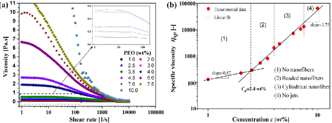
To determine the optimum concentration of PEO solution for forming cylindrical nanofibers, it is essential to study the rheological properties of the PEO solution prior to electrospinning. Figure 3a shows that the viscosity of PEO solution decreases with increasing shear rate for all the measured concentrations (1~10 wt%) in this study. Whereas for a more concentrated solution (≧ 4.0 wt%), the viscosity declines more rapidly, especially for concentration ≧ 6.0 %. The viscosity of the lower concentration solutions is technically constant at lower frequencies.
Shear thinning is the non-Newtonian behavior of fluids whose viscosity decreases under shear rate [36]. It is supposed that with the increase of shear rate the polymer chains start to change from an “entangled” state to an “unentangled” or “oriented” state by stretching forces [36]. In the “oriented” state, polymers have less resistance of flowing (i.e. shear deformation) originating from smaller viscosity. However, only when shear rate is higher than the inverse of the polymer relaxation time, the phenomenon of shear thing can be observed [36]. It is also worth noting that in Figure 3a at the lower shear rate, the viscosity is
10
constant and independent of the shear rate for solutions with low concentration. Moreover, the critical value of shear rate when viscosity begins to decline, decreases with the increase of concentration, suggesting a relationship between polymer relaxation time and polymer concentration.
Apparently, intrinsic viscosity [η] is an important variable to describe the relation between solution viscosity and concentration. It is defined as (14)
c csp c c
lim
lim
0 0 0
0
(14)
Where η0 is the viscosity of the solvent, η is the dynamic viscosity of the solution, ηsp is the specific viscosity and c is the mass fraction concentration. As defined here, intrinsic viscosity [η] is a dimensional number, which is the slope of plot of specific viscosity ηsp versus concentration c. In this paper, dynamic viscosity η measured at a shear rate 1 s-1 was used to calculate specific viscosity ηsp.
Figure 3b shows the log-log plot of the specific viscosity versus the polymer solution concentration. For our dilute solutions, the relation of specific viscosity and the concentration is a power law with an exponent of 0.87. Upon the concentration reaches 2.4 wt%, the specific viscosity increase rapidly with a constant slope of 3.75, thus suggesting that entanglements among polymer chains increase, resulting in a semi-dilute solution regime.
Therefore, the entanglement concentration can be determined by a crossover point (~2.4 wt%) [37]. Theoretically, the exponent for the power law relation between viscosity and concentration in the entangled solution regime is 4.7 for a polymer in a Θ solvent and 3.9 for a polymer in a good solvent [38]. The exponent of PEO/water/ethanol is 3.75, which can confirm that the solvent mixture is a good solvent for PEO at 25 °C.
11
Figure 3. (a) Viscosity as a function of shear rate for different PEO concentration in wt%; (b) dependence of specific viscosity on concentration. The entanglement concentration is indicated as 2.4
wt% by crossover of two slopes. All the measurements were taken at room temperature (25 ℃).
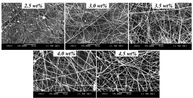
The chain entanglements are important for fiber formation reported in the pioneering studies of Long and Wilkes [39, 40]. According to the N-ES from different concentrations, the plot of specific viscosity and concentration is divided into four regions (see Figure 3b). Below the entanglement concentration where there are not enough entanglements among polymer chains, the solution viscosity is mainly controlled by intramolecular excluded- volume effects. As a result, no polymer fibers are obtained. As the concentration is further increased above the entanglement concentration, the solution turns to the semi-dilute entangled regime introduced by chain entanglements, which have a dominant effect on the solution rheological properties. For capillary electrospinning beaded fibers are observed in the concentration range of 2.5-4.5 wt%. When the concentration of PEO solution exceeds 4.5 wt%, cylindrical fibers are formed which can be confirmed by the SEM images in Figure 4.
The chain entanglements increased sufficiently to produce nanofibers with a proper morphology. The concentration is approximately the double of the entanglement concentration, which is in good agreement with the results of Wilkes and Long [39]. When the concentration is greater than 7.5 wt%, the solution is extremely hard to be transferred through the needle because of the more viscous solution and the thinner needle diameter.
Thus, the limited solution concentrations ranging from 4.5 wt% to 7.5 wt% are available to produce defect-free nanofibers for electrospinning.
12
Figure 4. SEM images of the PEO nanofibers from different solution concentrations generated by N-ES
4.2. The shear-aided corona electrospinning (SAC-ES) process
At the SAC-ES process, the polymer solution is pumped through the orifice between the rotating inner part (rotor) and the metal stator having a sharp edge. Subsequently, as the gap is filled up with solution, the solution comes out and the liquid meniscus touches the sharp edge. Simultaneously, the metal outer part is charged by high voltage via the high voltage D.C. power supply. Consequently, when the voltage is sufficient to provide electrical force enough to overcome the surface tension, numerous jets are formed and initiated along the circular edge. The rotation has another advantage as it can make the solution dispersed along the orifice and the sharp spinneret edge more efficiently. Figure , the images taken by high-speed camera, illustrates that the rotation of the inner part of the spinneret is helpful for both the distribution of the solution and the forming Taylor-cones and jets. It can be seen from Figure 5a, that without rotation the solution overflows from the edge, then forms big droplets sticking onto the surface of the outer part. There was some solution flowing back to the top surface of the plastic inner part as well. The sites of the Taylor-cones and the ejected jets (indicated by numbers) were random due to the above-mentioned overflow (Figure 5a).
Compared to the case where the inner part is rotating (Figure 5b, 5c) the edge of the spinneret was cleaner and at the rotation speed of 110 rpm, the jets organized themselves in even distances (see Figure 5b). When the rotation speed was further increased up to 440 rpm, more jets were generated (Figure 5c). On the other hand, the sites of the jets were located along the circular orifice. We can conclude that rotation facilitates fiber formation.
13
Figure 5. Jet and Taylor-cone formation along the electrode edge under different rotation speeds: (a) 0 rpm, (b) 110 rpm, (c) 440 rpm
4.3. Effect of rotation speed on the critical voltage to initiate jets
Rotation speed was considered as a significant factor to affect the critical voltage to initiate jets. In this experiment we chose 4.5 wt% PEO solution based on the previous results of the rheological analysis, The rotation speed of the spinneret inner part (i.e. rotor) with 0.5 mm gap size was set to 0, 10, 40, 60 and 100 rpm which can generate a shear rate of 0, 50, 205, 310 and 515 1/s and collecting distance was kept 200 mm to investigate the effect of rotation speed . The PEO fibers were produced at different rotation speeds and relevant different threshold voltages related to jet formation.
Moreover, Figure 6 shows that the voltage threshold diminished as the rotation speed increased . This gives a strong evidence that the polymer solution subjected to shearing deformation shows easier jet initiation, which can be originated from the in-situ decreased solution viscosity. When reaching lower viscosity, the entanglements of the intermolecular chains become less numerous, leading to less resistance to electrical forces, thereby weaker electric field intensity is enough to initiate the jets. Briefly, rotation speed greatly reduces threshold voltage. The critical voltage of 35 kV was reduced below 20 kV at the lowest rotation speed tested, and down to only12 kV when reaching 100 rpm. And above 100 rpm, there was no significant change in critical voltage. Comparing the diameter distributions, it can be found that fibers obtained by rotating the inner part possess highly similar diameter
14
and standard deviation (SI Figure S1), suggesting a stable and equivalent process when the voltage threshold is reached.
0 20 40 60 80 100
10 15 20 25 30 35 40
Rotation speed [rpm]
Critical voltage [kV]
Figure. 6 Effect of the rotation speed on the threshold voltage. The spinning condition: PEO concentration is 4.5 wt%, gap size is 0.5 mm, collecting distance is 200 mm.
4.4. Effect of gap size on fiber diameter
As the gap size and the rotation speed can change the viscosity of the polymer solution,we set different rotation speeds for each gap size to keep the same viscosity. Based on the rheology measurements, We chose the viscosity of 0.3 Pas for all h gap sizes, which corresponds to the shear rate of 2205 1/s. Maintaining the fixed shear rate means that different rotation speeds had to be set for the different gap sizes. Therefore, we used equation (6) derived in Section 2, the rotation speed for each gap size was calculated from the following equation (15):
] R [
2 h 60
1
rpm
(15)
where Ω [rpm] is the rotation speed of inner part, h [mm] is the gap size, R1 [mm] is the radius of the inner part’s edge,
[1/s] ̇is shear rate, respectively. The gap sizes and rotation speeds were obtained and summarized in Table 1.
Table 1. The rotation speed of inner part for each gap size
Gap size [mm] 0.2 0.5 1.0 1.5 2.0
Rotation speed corresponding to
0.3 Pa·s viscosity [rpm] 180 440 880 1320 1760
15
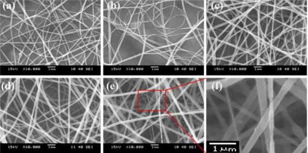
The effect of variable gap sizes, from 0.2 to 2 mm, on the fiber morphology can be seen in Figure 7 via SEM images. The spinneret of 2 mm gap produced fibers with 37.6% thicker average diameter compared with 0.2 mm gap. As shown in Figure 7c, the nanofibers with relatively uniform diameter and smooth surface were obtained from the gap size of 1 mm.
While the fibers produced from a gap size of 0.2 mm and 2.0 mm both have higher deviation (Figure 9). Some thicker fibers were identified in the case of 0.2 mm. Here, although the viscosity was the same in all the cases, some solution could be squeezed out of the edge at the same flow rate because of higher flow resistance and smaller capacity of small gap orifice, which results in thicker fibers. In contrast, when the gap size was 2.0 mm, some fine fibers with diameter of less than 100 nm and some fibers showing contractions (Figure 7f) were identified. The formation mechanism of these thin fibers can be explained by the highest rotation speed in the case of 2.0 mm gap size, which could provide additional stretching caused by centrifugal forces that resulted in further stretching of the forming fibers.
Formation of fibers containing these contractions is different from beaded fibers commonly formed in electrospinning. Fibers with multiple contractions were possibly caused by stress-oscillation. Stress-oscillation taking place in bigger specimens results in the ribbed structure of specimens that can be observed by the naked eyes when they are subjected to specific tensile conditions. Our observations at a smaller scale are somewhat similar to these ribbed specimens. In the work of Ronkay and Czigany [41] it is stated that at stress- oscillation observed during tensile tests of dumbbell specimens, shear stresses arise during the molecular chains orienting under the effect of the stretching forces. As a result, the thermoplastic material splits into molecular bundles and between these oriented parts, small cracks appear. In their study, stresses cause molecular orientation and crystallization, micro-cracks caused by orientation changes the heat conductivity, because of which, local overheating leads to crystal melting. In our case, local stretching of the molecules can take place by the electrostatic forces and mechanical forces from acceleration. Instead of the time-dependent balance of crystallization and heat-transfer (re-melting), here the oscillation originates from the fragile balance of the fiber drawing electrostatic forces (resulting in molecular orientation) and the surface tension of the polymer solution. The stretched and oriented parts can be recovered to their original molecule shapes by the surface tension, which becomes dominant shortly from time to time.
16
The trend of average diameter increases with the increase in gap size (see Figure 9). It should be kept in mind that the smaller the open surface is, the more easily the jets can be pulled out from the solution surface because of the higher charge density.
Figure 7. SEM images of nanofiber with the same viscosity from different gap sizes: (a) 0.2 mm; (b) 0.5 mm; (c) 1 mm; (d) 1.5 mm; (e) 2.0 mm;(f) ultra-fine and contracted fibers
4.5. Effect of polymer solution concentration on the fiber diameter
To quantitatively evaluate the effect of polymer solution concentration, nanofibers were generated from three concentrated solutions with concentrations of 6.0, 7.0 and 7.5 wt%
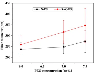
considering the shear-thinning phenomenon during the SAC-ES with a 0.5 mm gap. The morphology of fibers obtained by N-ES with 0.51 mm needle from the same above- mentioned solutions were also compared (SI Figure S2) under the same other process parameters (35 kV voltage, 20 cm collecting distance). Rotation speed for SAC electrospinning was fixed at 100 rpm (shear rate of 515 s-1) in these studies. As can be seen from Figure 8, the average diameter increased from 259.2 ± 43.5 to 347.0 ± 78.0 nm with the increase of the polymer concentration from 6.0 to 7.5%. It has the similar tendency as for N- ES. Viscosity of the polymer solution increases with the increase of PEO concentration, leading to less stretched jets. For N-ES, the average fiber diameter was less than that of SAC- ES, as depicted in Figure 8. According to the results discussed above, one can conclude that electric field intensity around the small needle tip (with a diameter of 0.51 mm) is greater than that around the much bigger SAC-ES spinneret. These results indicate that the effect of electric field intensity is stronger than that of the rotation speed at 100 rpm.
17
6.0 6.5 7.0 7.5
200 250 300 350 400 450
N-ES SAC-ES
Fiber diameter [nm]
PEO concentration [wt%]
Figure 8. Fiber diameter as a function of PEO concentration for N-ES (with a 0.51 mm needle) and SAC-ES (with a 0.5 mm gap).
4.6. Comparison of fibers obtained from SAC-ES and N-ES
To understand the effect of gap size on the nanofibers better, the comparison between N- ES and SAC-ES was carried out. The characteristic size, which describes the geometry of the electrospinning surface, is the capillary diameter at N-ES, while at SAC-ES it is considered to be the gap size. As described in section 3.4, five blunt needles with different inner diameters were used to electrospin PEO solution under the same conditions. The results from given rotation speeds in Table 1 were obtained and presented in Figure 9. Both N-ES and SAC-ES had an increasing tendency of fiber diameters with the increase of the characteristic size (needle diameter and gap size, respectively). Increasing the characteristic size leads to bigger solution surface (i.e. liquid meniscus) and decreased charge density. Therefore, the reason for the increasing fiber diameter is probably related to this decreased charge density of the solution surface.
0.0 0.4 0.8 1.2 1.6 2.0
100 150 200 250 300 350 400
gap size needle size
Fiber diameter [nm]
Characteristic size [mm]
18
Figure 9. Effect of gap size from SAC-ES and needle diameter from N-ES on fiber diameters
We also compared the morphology of fibers produced by N-ES (needle diameter of 1.32 mm) and SAC-ES (gap size of 1.5 mm). Firstly non-rotating process was compared with N-ES where the solution viscosity for both processes was the same. Additionally, the comparison between rotating (1320 rpm) and non-rotating process was made to show the effect of rotation. Figure 10 shows the morphology of nanofibers obtained by the three different electrospinning processes. Fiber diameters from N-ES are more homogenous (Figure 10a). It is interesting to note that there are not only some very fine fibers but also some thick ones in SAC-ES formed in non-rotating process, as shown in Figure 10b. We can recall the image of the spinneret without rotation depicted in 5a. The solution was distributed unfavorably along the spinneret orifice, e.g. it covered the side surface of the outer metal part, the edge of the outer metal part and even the top surface of the plastic inner part. Because there was no rotation to disperse the solution, solution overflew at the position close to the inlet and stuck to the side surface of the metal part where some jets were formed. When the solution was on the top surface of the plastic part, thick fibers were formed because of the big solution surface and the poor conductivity of the plastic part. On the other hand, the fine fibers were generated from the gap or edge of the metal part resulting from the high electric field intensity. When the inner part of the spinneret rotates, the fiber diameters became more homogeneous, and smaller than that of nanofibers produced without rotation, which originates from the viscosity decrease induced by rotation (Figure 10c).
Figure 10. SEM images of nanofibers from (a) N-ES, (b) non-rotating process, (c) rotating process at 1320 rpm.
The fiber diameter distributions can be seen in Figure 11. We hypothesized that different spinnerets (N-ES vs. SAC-ES) might lead to differences in fiber diameter distribution, and
19
rotation might also be an important parameter to influence fiber morphology. For the statistical comparison, the χ2 test was used.
Figure 11. Fiber diameter distribution from different electrospinning processes (1.32 mm needle, 1.5 mm gap with rotating and non-rotating). (*: p < 0.05, significant difference)
As expected, it was found that the fiber diameter distributions from N-ES and non-rotating SAC-ES were significantly different from each other as indicated by p = 5.65×10⁻⁹ < 0.05.
While the fibers were slightly thinner than those from N-ES when the shearing deformation was applied on the polymer solution. In this case, p = 0.277 denotes that they have similar fiber diameter distributions. By comparing the non-rotating and the rotating SAC-ES process, it is found that the fiber diameters were significantly different for the fibers obtained from the two different processes with a p value much less than 0.05. What’s more, the average fiber diameter was decreased by 16.5% in rotation process compared with non-rotating process. Therefore, we can conclude that rotation can provide a positive effect on the forming fibers, because it can decrease polymer solution viscosity, and also prevents the overflow of the solution during the SAC-ES process. Furthermore, the flow rate of SAC-ES with the small prototype was 15 ml/h, which is at least 15-folds higher than that of N-ES, and scaling up of the current 50 mm diameter spinneret is easy. Therefore, SAC-ES can be considered as a potential needless electrospinning technique to enhance nanofiber production and which operates voltages much smaller than other needleless techniques.
20 5. Conclusions
In this study shear stresses were applied on the polymer solution to enhance polymer jet formation during electrospinning. The shear aided electrospinning (SAC-ES) approach proposed here helped in reducing threshold voltage for jet initiation. Due to the shearing deformation of the polymer solution by the relative motion between two cylindrical parts of the spinneret, viscosity of solution can be decreased, resulting in lower threshold voltage for jet initiation. When the rotation speed was higher than 60 rpm, electrospinning started at a relatively low voltage of 12 kV. The effects of solution concentration on the fiber diameter were the same in SAC-ES and N-ES. We also concluded that the characteristic size, i.e.
capillary diameter and gap size has the same affecting tendency on average fiber diameters.
When the gap size increased from 0.2 mm to 2 mm, but the same applied shear rate , the fiber diameter was increased by 37.6%. The diameter distributions of fibers from the non- rotating SAC-ES (gap size of 1.5 mm) and N-ES (needle diameter 1.32 mm) were significantly different based on the statistical analysis. When shearing was applied by rotation, the average fiber diameter was decreased by 16.5%, which was slightly smaller than that of fiber produced from N-ES (needle diameter 1.32 mm). Overall, the present work provides a facile and scalable electrospinning method for improving the controllability of solution viscosity in- situ, reducing the energy cost for manufacturing nanofibers. The method can produce nanofibers at large feeding rate (15 ml/h for the small spinneret), low electrospinning voltage (12 kV) and with the minimized free solution surface to reduce the solvent evaporation.
References
1. Reneker DH, Yarin AL, Zussman E, Wu H (2007) Electrospinning of nanofibers from polymer solutions and melts. Adv. Appl. Mech. 41: 43.
2. Mokhena TC, Jacobs V, Luyt AS (2017) Electrospun alginate nanofibres as potential bio-sorption agent of heavy metals in water treatment. Express Polym. Lett. 11: 652.
3. Márquez Y, Graupera J, del Valle LJ, Turon P, Franco L, Puiggalí J (2017) Poly(epsilon- caprolactone) films reinforced with chlorhexidine loaded electrospun polylactide microfibers. Express Polym. Lett. 11: 674.
21
4. Lomov SV, Molnár K (2016) Compressibility of carbon fabrics with needleless electrospun PAN nanofibrous interleaves. Express Polym. Lett. 10: 25.
5. Patra HK, Sharma Y, Islam MM, Jafari MJ, Murugan NA, Kobayashi H, Turner APF, Tiwari A (2016) Inflammation-sensitive in situ smart scaffolding for regenerative medicine. Nanoscale 8: 17213.
6. Dong RH, Jia YX, Qin CC, Zhan L, Yan X, Cui L, Zhou Y, Jiang X, Long ZY (2016) In situ deposition of a personalized nanofibrous dressing via a handy electrospinning device for skin wound care. Nnaoscale 8: 3482.
7. Szabó E, Démuth B, Nagy B, Molnár K, Farkas A, Szabó B, Balogh A, Hirsch E, Nagy B, Marosi G, Nagy ZK (2018) Scaled-up preparation of drug-loaded electrospun polymer fibres and investigation of their continuous processing to tablet form. Express Polym.
Lett. 12: 436.
8. Zhang H, Qin X, Wu J, He Y, Du H, Li B, Kang F (2015) Electrospun core-shell silicon/carbon fibers with an internal honeycomb-like conductive carbon framework as an anode for lithium ion batteries. J. Mater. Chem. A 3: 7112.
9. Theron S A, Zussman E, Yarin AL (2004) Experimental investigation of the governing parameters in the electrospinning of polymer solutions. Polymer 45: 2017.
10. Tian L, Zhao C, Li J, Pan Z (2015) Multi-needle, electrospun, nanofiber filaments:
effects of the needle arrangement on the nanofiber alignment degree and electrostatic field distribution. Text. Res. J. 85: 621.
11. Yang Y, Jia Z, Li Q, Hou L, Liu J, Wang L, Guan Z, Zahn M (2010) A Shield Ring Enhanced Equilateral Hexagon Distributed Multi-needle Electrospinning Spinneret. IEEE Trans.
Dielectr. Insulation 17: 1592.
12. Theron SA, Yarin AL, Zussman E, Kroll E (2005) Multiple jets in electrospinning:
experiment and modeling. Polymer 46: (2889-2899).
13. Akampumuza O, Gao H, Zhang H, Wu D, Qin X (2018) Raising nanofiber output: The progress, mechanisms, challenges, and reasons for the pursuit. Macromol. Mater.
Eng. 303: UNSP 201700269.
14. Niu HT, Wang XG, Lin T (2012) Needleless electrospinning: influences of fibre generator geometry. J. Text. Inst. 103: 787.
15. Yalcinkaya B, Callioglu FC, Yener F (2014) Measurement and analysis of jet current and jet life in roller electrospinning of polyurethane. Text. Res. J. 84: 1720.
22
16. Niu HT, Lin T, Wang XG (2009) Needleless Electrospinning. I. A comparison of cylinder and disk nozzles. J. Appl. Poly. Sci. 114: 3524.
17. Wang X, Niu HT, Lin T, Wang XG (2012) Needleless Electrospinning of uniform nanofibers using spiral coil spinnerets. J. Nanomater 2012: 3.
18. Lu BG, Wang YJ, Liu YX, Duan HG, Zhou JG (2010) Superhigh-throughput needleless electrospinning using a rotary cone as spinneret. Small 6: 1612.
19. Jiang GJ, Zhang S, Qin XH (2013) High throughput of quality nanofibers via one stepped pyramid-shaped spinneret. Mater. Lett. 106: 56.
20. Thoppey NM, Bochinski JB, Clarke LI, Gorga RE (2010) Unconfined fluid electrospun into high quality nanofibers from a plate edge. Polymer 51: 4928.
21. Thoppey NM, Bochinski JB, Clarke LI, Gorga RE (2011) Edge electrospinning for high throughput production of quality nanofibers. Nanotechnology 22: 1-12.
22. Liu Z, Ang KJ, He JH (2017) Needle-disk electrospinning inspired by natural point discharge. J. Mater. Sci. 52: 1823.
23. Liu Z, Chen RX, He JH (2016) Active generation of multiple jets for producing nanofibres with high quality and high throughput. Mater. Des. 94: 496.
24. Ali U, Niu HT, Aslam S, Jabbar A, Rajput AW, Lin T (2017) Needleless electrospinning using sprocket wheel disk spinneret. J. Mater. Sci. 52: 7567.
25. He HJ, Liu CK, Molnar K (2018) A Novel Needleless electrospinning system using a moving conventional yarn as the spinneret. Fibers. Polym. 19: 1472.
26. Molnar K, Zsombor N (2016) Corona-electrospinning: Needleless method for high- throughput continuous nanofiber production. Eur. Polym. J. 74: 279.
27. Yan XR, Marini J, Mulligan R, Deleault A, Sharma U, Brenner M P, Rutledge GC, Freyman T, Pham QP (2015) Slit-Surface Electrospinning: A novel process developed for high-throughput fabrication of core-sheath fibers. PLoS One 10: UNSP e0125407.
28. Vysloužilová L, Buzgo M, Pokorný P, Chvojka J (2017) Needleless coaxial electrospinning: A novel approach to mass production of coaxial nanofibers. Int. J.
Pharm. 516: 293.
29. Yan GL, Niu HT, Shao H, Zhao XT, Zhou H, Lin T (2017) Curved convex slot: an effective needleless electrospinning spinneret. J. Mater. Sci. 52: 11749.
23
30. Wei L, Qiu Q, Wang R and Qin X (2018) Influence of the processing parameters on needleless electrospinning from double ring slits spinneret using response surface methodology. J. Appl. Polym. Sci. 135: 46407.
31. Chen X, Zhang Y, He X, Li H, Wei B, Yang W (2019) Electrospinning on a plucked string.
J. Mater. Sci. 54: 901.
32. Jahan I, Wang L, Wang X (2019) Needleless electrospinning from a tube with an embedded wire loop. Macromol. Mater. Eng. 304: 1800588.
33. Zhang Y, Zhang L, Cheng L, Qin Y, Li Y, Yang W, Li H (2018) Efficient preparation of polymer nanofibers by needle roller electrospinning with low threshold voltage.
Polym. Eng. Sci., DOI: 10.1002/pen.24993.
34. Molnár , Kaszás G (2018) High Productivity Shear-aided electrospinning apparatus and method thereof US 62/765, 216.
35. Press WH, Teukolsky SA, Vetterling WT, Flannery BP (2007) Numerical Recipes in C, The Art of Scientific Computing, Second Edition, Cambridge university press.
36. Fall A, Bonn D (2012) Shear thickening of Laponite suspensions with poly(ethylene oxide). Soft Matter. 8: 4645.
37. Chisca S, Barzic Al, Sava I, Olaru N, Bruma M (2012) Morphological and rheological insights on polyimide chain entanglements for electrospinning produced fibers. J.
Phys. Chem. B 116: 9082.
38. Rubinstein M, Colby RH (2003) Polymer Physics, Oxford University Press: London.
39. McKee MG, Wilkes GL, Gobby RH, Long TE (2004) Correlations of solution rheology with electrospun fiber formation of linear and branched polyesters. Macromolecules 37: 1760.
40. Gupta P, Elkins C, Long TE, Wilkes RH (2005) Electrospinning of linear homopolymers of poly(methyl methacrylate): exploring relationships between fiber formation, viscosity, molecular weight and concentration in a good solvent. Polymer 46: 4799.
41. Ronkay F, Czigány T (2006) Cavity formation and stress-oscillation during the tensile test of injection molded specimens made of PET. Polym. Bull. 57: 989.
42. Landau L, Lifshitz EM (1959) Fluid Mechanics Pergamon. New York 61.
43. Stokes GG (1845) On the theories of the internal friction of fluids in motion and of the equilibrium and motion of elastic solids, in Mathematical and Physical Papers, pp.
102-104, Cambridge, UK: Cambridge University Press, 1880.
24
44. Taylor GI (1923) Stability of a Viscous Liquid Contained between Two Rotating Cylinders, Philosophical Transactions of the Royal Society of London. Series A 223:
289–343.
45. Yan G, Niu H, Zhou H, Wang H, Shao H, Zhao X, Lin T (2018) Electro-aerodynamic field aided needleless electrospinning, Nanotechnology 29: 235302.
46. Avila K, Moxey D, Lozar A, Avila M, Barkley D, Hof B (2011) The Onset of Turbulence in Pipe Flow, Science 333: 192.
Acknowledgements
This work was supported by the Higher Education Excellence Program of the Ministry of Human Capacities in the framework of the Nanotechnology research area of the Budapest University of Technology and Economics (BME FIKP-NANO), the Hungarian Research Fund (OTKA K100949, PD116122), the ÚNKP-17-4-I New National Excellence Program of the Ministry of Human Capacities and BME-KKP, Stipendium Hungaricum Scholarship of Tempus Public Foundation, and China Scholarship Council (201700500073).