1. Introduction
One of the ever-growing challenges in the pharma- ceutical industry is developing suitable formulations for poorly soluble active pharmaceutical ingredients [1, 2]. Combinatorial chemistry and high throughput screening aided drug discovery lead to an ever-grow- ing quest for potency. This, however, comes with a price, as these molecules are usually characterized by higher molecular weight, higher lipophilicity, and poor aqueous solubility [3, 4]. The phenomenon of molecular obesity [5] puts a growing pressure on for- mulation scientists to develop suitable dosage forms,
which could improve the bioavailability of these drugs. It is estimated that more than 70% of newly synthesized drug candidates are characterized by low aqueous solubility. Thus, the burden to ensure ther- apeutic efficacy lies on the shoulders of pharmaceu- tical formulation scientists [6–8].
One of the newer approaches in achieving higher aqueous solubility and enhanced dissolution are the preparation of fiber-based formulations [9–11]. Due to the high surface area, high porosity, and the pos- sibility of amorphization of the actives, nano- and microfibrous mats can lead to improved aqueous
Scale-up and optimization of fenofibrate-loaded fibers electrospun by corona-electrospinning
E. Bitay1,2, Z.-I. Szabó3, J. Kántor1, K. Molnar4,5, A. L. Gergely1*
1Department of Mechanical Engineering, Faculty of Technical and Human Sciences, Targu-Mureş, Sapientia Hungarian University of Transylvania, Corunca, 1C, 540485 Târgu-Mureş, Romania
2Research Institute of the Transylvanian Museum Society, 2–4 Napoca, 400009 Cluj, Romania
3Department of Pharmaceutical Industry and Management, George Emil Palade University of Medicine, Pharmacy, Science, and Technology of Târgu-Mureş, Gh. Marinescu 38, 540485 Târgu-Mureş, Romania
4Department of Polymer Engineering, Faculty of Mechanical Engineering, Budapest University of Technology and Economics, Műegyetem rkp. 3–9, H-1111 Budapest, Hungary
5MTA–BME Research Group for Composite Science and Technology, Műegyetem rkp. 3, H-1111 Budapest, Hungary
Received 27 July 2020; accepted in revised form 25 September 2020
Abstract.Scaled-up production of fenofibrate-loaded, polyvinylpyrrolidone-based microfibrous mats was achieved by using corona-electrospinning. An experimental design-based approach was used to study the influence of production parameters on fiber diameter and morphology. Microstructural characterization of the obtained products was performed by scanning electron microscopy imaging and differential scanning calorimetry. Drug content and in vitrodissolution studies were per- formed in order to monitor the effect of electrospinning on the drug release characteristics from the obtained product. The optimized parameters provided electrospun mats with smooth, homogenous fibers, without beading, which conferred rapid drug release and increased solubility of the lipid-lowering drug. The in vitrodissolution results show 40 times higher fenofi- brate release from the fiber mats compared to the micronized active pharmaceutical ingredient. The presented results show that corona-electrospinning is a promising method for scale-up applications, and it could be used in the pharmaceutical in- dustry. The fenofibrate loaded microfibrous mats could treat dyslipidemia, thus prevent heart attack or stroke, by using lower drug content. Lower drug content could also reduce the associated side effects and lowers the cost of treatment.
Keywords:processing technologies, corona-electrospinning, drug release, fenofibrate, scale-up https://doi.org/10.3144/expresspolymlett.2021.32
*Corresponding author, e-mail:agergely@ms.sapientia.ro
© BME-PT
solubility of the incorporated drugs [12–15]. Among the different approaches used in fiber formation, electrospinning is probably the most popular. This versatile technique utilizes electrostatic forces to ob- tain ultrafine fibers from viscous, polymeric solu- tions. Several advantages of this approach include rapid drying speed, ease of use, and compatibility with labile active pharmaceutical ingredients, making it an ideal candidate for preparing nano-amorphous solid dispersions of poorly water-soluble drugs [10, 16]. The working principle of the electrospinning method is extensively discussed in the literature.
Briefly, the polymer solution is constantly fed to the spinneret, which is connected, usually, to the positive potential of the power supply, whereas the collector is grounded. Since the polymer solution is charged, the droplet at the spinneret distorts to form a so- called Taylor cone [17]. When the stresses originat- ing from the repulsion forces exceed the surface ten- sion of the polymer solution, polymer jets form that travel towards the grounded collector due to the elec- trostatic attraction. In the process, most of the sol- vent evaporates, thus forming solid fibers on the col- lector [18–20].
Kenawy et al. [21] reported the first example of med- icated solid dispersions prepared by solution electro- spinning, using tetracycline hydrochloride as a model drug and poly(ethylene-co-vinyl acetate) (PEVA), poly(lactic acid) PLA, and a blend of PEVA and PLA in a 50/50 ratio. The authors investigated the drug release kinetics of the solid dispersions, electrospun fiber mats, and casted films. The results indicated that the release of tetracycline hydrochloride from the PEVA fiber mats was 6 times higher (~60%) than that of the film (~10%) after 120 hours. Furthermore, the PEVA and PEVA/PLA fiber mats showed a con- tinuous release profile, while the films of the same material indicated an instantaneous release in the first 10 hours reaching the maximum level. The au- thors explained this behavior with the high surface area of the fiber mats compared to that of the films.
Based on the findings of Kenawy et al. [21], several publications discuss the preparation of solid disper- sions via electrospinning using different polymer- drug combinations [9, 22].
Fenofibrate (FEN) is used to treat dyslipidemia, a health condition that manifests in abnormal lipid lev- els, fatty substances in the blood, such as triglycerides and cholesterol. High lipid content in the blood, if not treated, could cause plaque deposition on the
walls of blood vessels resulting in the development of adverse cardiovascular events, such as heart attack or stroke [23, 24]. However, FEN is classified as a BCS class II drug, meaning it is highly lipophilic (logP= 5.3) and insoluble in water [24]. To improve the solubility of the drug, Sipos et al. [25] prepared solid dispersion using a single needle electrospinning system (SNES) to incorporate FEN into polyvinyl pyrrolidone (PVP) fibers. The electrospinning process resulted in smooth-surfaced, randomly oriented, bead free fibers with an average diameter of 1.10±0.23 μm.
The DSC results indicated that during the electro- spinning process, the incorporation of FEN into the PVP fibers resulted in the amorphization of the drug.
The FEN loaded PVP fiber mat disintegrated in 6 seconds, producing an instantaneous drug release of
~92%, producing an over 40 times higher dissolution rate when compared to the micronized drug.
One of the bottlenecks of the conventional SNES technique is the low throughput [26, 27]. Industrial scale-up approaches are based on increasing the num- ber of Taylor cones and can usually be divided into multi-needle techniques and free surface electrospin- ning [28]. In the former case, productivity is increased by increasing the number of needles employed. This technique, however, comes at the price of alteration of the electric field profile, due to the electric inter- actions of multiple nearby charged jets [29]. A fur- ther disadvantage of this approach is the operation and maintenance difficulties since the number of needles can reach thousands. At this point, cleaning the spin- neret becomes quite challenging, and clogging dur- ing the electrospinning process raises serious opera- tional difficulties [29, 30].
In the case of the needless electrospinning-based tech- niques, numerous jets are usually initiated from a free- surface of the polymeric solution [31]. There are many promising techniques reported in the literature [31–
38]; however, generally, due to the use of a large liq- uid surface, water absorption and solvent evaporation influence the composition of the polymer solution that could lead to undesirable effects on the electrospin- ning process. These methods usually need a higher voltage (>50 kV) than that of the single needle setup.
In order to minimize the large liquid surface and thus the associated negative effects on the polymer solu- tion composition, corona-electrospinning was devel- oped by Molnar and Nagy [39]. He et al. [40] were able to produce PEO fibers at a voltage as low as 12 kV with a modified corona-electrospinning device.
In the present study, the high-throughput production of FEN-loaded microfibers was explored, using the newly introduced corona-electrospinning approach.
The aim was not only a quantitative leap in produc- tion but also to obtain FEN loaded fiber mat similar quality of the SNES-based product. FEN-loaded PVP fiber mats were successfully produced by the high throughput corona-electrospinning method. The dis- solution study results indicate similar FEN release behavior for samples prepared by corona-electro- spinning to the ones that were prepared by the SNES method.
2. Materials and methods 2.1. Materials
Micronized FEN was obtained as a gift sample from a local pharmaceutical company in Târgu Mureş, Romania. Ethanol (Merck, ACS grade), Tween 80 (Sigma-Aldrich), polyvinyl pyrrolidone (PVP, Alfa Aesar, 58 000 g/mol, K29/32) were obtained through local vendors and used as received without further purification.
2.2. Preparation of polymeric solutions
To study the effect of Tween 80 alone and in combi- nation with FEN on fiber formation, three polymeric solutions were prepared: solution P contained PVP alone, solution P/T contained PVP and Tween 80, and solution P/T/F contained PVP, Tween 80 and FEN as presented in Table 1.
The concentrations of the polymeric solutions were based on the previous report for the SNES setup [25]. The polymeric solutions were prepared at room temperature using a JK SMS HS magnetic stirrer (JKI, Shanghai, China) at 500 rpm for approximately 30 minutes when a homogeneous, viscous solution was obtained.
2.3. Corona-electrospinning
The electrospinning procedure was performed on a corona-electrospinning device. The setup and work- ing principle are discussed in detail in an earlier
publication [39]. Briefly, the schematics of the co- rona-electrospinning setup is presented in Figure 1.
A syringe pump continuously feeds the spinneret through a hollow shaft while the spinneret rotates.
The solution fills up a distribution channel and then reaches the narrow, annular orifice outlet at the top of the spinneret. As the polymer solution reaches the opening and, thus, the sharp edge of the electrode, multiple Taylor-cones form, and this results in a great increase in the production rate. The spinneret rotates in order to evenly distribute the polymer solution along the orifice and to prevent local overflow. A max- imum of 300 ml/h feed rate has been achieved with the setup using 20 wt% PVP/ethanol (EtOH) solu- tion, producing fibers with ~550 nm diameter. In con- trast, the maximum flow rate with the SNES tech- nique was 8 ml/h, producing fibers with a similar diameter [39]. In a recent study, this spinneret was also used in AC mode that resulted in a 1200 ml/h throughput and submicron fibers [41].
The solution was loaded in a syringe that was placed into a syringe pump (SEP-10S Plus, Aitecs, Vilnius, Lithuania), which was connected through silicone tubing to the rotating spinneret. The diameter of the circular orifice was 110 mm, with a gap size of 0.5 mm. The rotation speed of the spinneret was fixed at 100 rpm. The positive electrode of the custom DC power source (MA NT-75/P, Nagykanizsa, Hungary) was connected to the spinneret, while the plate col- lector covered with aluminum foil was grounded.
During the experiments, we used various collector distances and voltages. The flow rate was set at the
Table1.Composition of the polymeric solutions used for electrospinning.
Sol. P [wt%]
Sol. P/T [wt%]
Sol. P/T/F [wt%]
FEN – – 02.5
Tween 80 – 06.5 06.4
PVP 33.1 30.9 30.2
Ethanol 66.9 62.5 60.9 Figure 1.Corona-electrospinning setup.
highest value, 80 ml/h, at which no spillover was ob- served on the orifice of the corona-electrospinning device, even at the lowest voltages applied. The ex- periments were carried out at standard laboratory conditions at ~23 °C and ~70% humidity.
2.4. Experimental design
Scouting experiments were performed to determine the limits of the electrospinning parameters for the ex- perimental design. The variables and their levels used in the experimental design are shown in Table 2. A 32 full factorial design was carried out on the three sets of data obtained from the three different solutions (PVP, PVP+Tween 80, PVP+Tween 80+FEN) to de- termine the effects of voltage (V) and electrode-col- lector distance (D) on the electrospinning process. The response variable was the average fiber diameter. A linear regression model was built based on the data.
The designs did not include replicated center points.
The data obtained from using the solution containing PVP+Tween 80 was also analyzed with response surface methodology (considering the 32full facto- rial design as a face-centered central composite de- sign with a single center point). In this case, a quad- ratic model was built, containing V, D, V·D, V·V, and D·Dterms. The statistical analysis was carried out in Minitab 16.
2.5. Scanning electron microscopy (SEM) SEM imaging was carried out on a JEOL JSM- 5200 scanning electron microscope at 15 kV potential and 20 cm working distance, on neat, non-sputter coated samples. In order to determine the diameter of the fibers, at least three images were taken at different parts of the samples. The diameter of the fibers was determined with the use of ImageJ software by meas- uring at least 50 random fibers for each sample.
2.6. Differential scanning calorimetry (DSC) DSC measurements were carried out using a Shi- madzu DSC-60 apparatus (Shimadzu Corporation, Kyoto, Japan). Samples (approx. 3–5 mg) were ac- curately weighed in aluminum pans, sealed and scanned from 30–160 °C, under air atmosphere, at
5 °C/min heating rate. An empty aluminum pan with a lid was used as a reference.
2.7. In vitrodissolution studies
Dissolution tests were carried out in an Erweka DT-80 dissolution apparatus (Erweka, Germany) equipped with rotating baskets (Apparatus 1). The temperature of the dissolution medium was main- tained at 37.0±0.5 °C; rotation speed was set at 100 rpm. Dissolution studies were performed in 250 ml of water. Sampling was performed manually at 1, 3, 5, 10, 20, and 30 minutes by withdrawing 3 ml of samples with a syringe. The dissolved FEN content was determined spectrophotometrically using a Shimadzu UV-1601PC UV-VIS spectrophotometer (Shimadzu, Kyoto, Japan) at 289 nm, in a 10 mm quartz cuvette.
2.8. UV-Vis spectroscopic investigation of the electrospun mats
Incorporation of the active substance in the polymer- ic mats and determination of drug content was de- termined by UV/Vis spectroscopy on the same Shi- madzu UV-1601PC UV-VIS spectrophotometer (Shi- madzu, Kyoto, Japan) using methanolic solutions.
3. Results and discussion 3.1. Fiber mat characterization
Previously, we reported the preparation of FEN loaded PVP fiber mats using the SENS method. PVP was chosen based on our experience and excellent results obtained for solubilization and dissolution rate enhancement purposes. FEN being a highly in- soluble drug, it was necessary to use a solubilizer to reach satisfactory FEN concentrations in the PVP so- lution. Solubilizers, such as Kolliphor RH 40, Kol- lisolv P124, Kolliphor EL, and Tween 80 were tested for this purpose, and satisfactory results were achieved with Tween 80 [25].
The corona-electrospinning process of all three so- lutions, shown in Table 1, resulted in PVP fibers with diameters ranging from 1.4 to 4 μm. Table 3 shows the electrospinning parameters used and the resulted fiber diameters. The fiber diameters produced from Table 2.The variables, levels, and the notation used in the experimental design-based optimization of the corona-electro-
spinning process.
Variable Units Low level
–1
Middle level 0
High level 1
Collector distance, D [cm] 10 13 16
Voltage, V [kV] 25 35 45
the solution containing PVP alone are higher than the previously reported values by Molnár and Nagy [39] with corona-electrospinning, however, the con- centration in our case was higher, ~33 wt% com- pared to 20 wt%. Fiber diameter reported by Sipos et al. [25] with the SNES setup from a solution contain- ing PVP, Tween 80, and FEN with the same concen- tration was 1.10±0.23 μm, while in our case, it varies from 2.1 to 4 μm depending on the electrospinning parameters. Sample P/T/F_D13_V45, used in the dis- solution study, has an average fiber diameter of 2.2±0.72 μm, which is approximately double the size compared to the fiber diameter obtained using the SNES method.
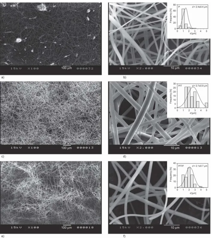
Figure 2 shows representative SEM images of the obtained fiber mats at 100× and 2000× magnifica- tion for samples P_D10_V45, P/T_D10_V45, and P/T/F_D10_V45. Fibers from all three solutions at
all electrospinning parameters were randomly orient- ed, cylindrical and smooth-surfaced. The investiga- tion of the SEM images of the samples shows that in a few cases, beads appear on the fibers. Almost all the fiber mats generated from solution P show bead- ing, whereas it seems that the addition of Tween 80 to the solution results in less beading. It has been re- ported that the addition of Tween 80 to the polymeric solution reduces the surface tension of the solution and improves the fiber morphology by reducing beading [42]. The solution containing PVP, Tween 80 and FEN produce samples with less beading, which is most probably due to the concentration increase in addition to the effect of Tween 80 [42].
To study the effect of the electrospinning parameters and the polymer solution composition on the fiber diameter, a 32full factorial experimental design was employed. The ANOVA table is presented in Table 4 and 5 for the studied fiber mats, whereas Figure 3 il- lustrates various plots.
For samples electrospun from solution P, thus con- taining PVP alone, the 0.022 p-value for the voltage is lower than 0.05 (Table 4), indicating that the trend seen in the data is probably not due to random chance only. The effect of the electrode-collector dis- tance with its p= 0.143 showed no statistical signif- icance in the 95% confidence interval.
Table 3.Corona-electrospinning parameters and the result- ing fiber diameters.
*Sample name is constructed as follows: polymeric solution com- position_distance_applied voltage.
Sample name* D [cm]
V [kV]
d
[μm] Beads
P_D10_V25 10 25 2.4±0.8 Y
P_D10_V35 10 35 2.4±1.1 Y
P_D10_V45 10 45 1.4±0.4 Y
P_D13_V25 13 25 3.0±1.0 Y
P_D13_V35 13 35 2.3±0.8 Y
P_D13_V45 13 45 1.7±0.6 N
P_D16_V25 16 25 3.0±1.0 Y
P_D16_V35 16 35 2.4±0.9 Y
P_D16_V45 16 45 2.3±0.6 Y
P/T_D10_V25 10 25 2.2±0.7 Y
P/T_D10_V35 10 35 2.6±0.8 Y
P/T_D10_V45 10 45 2.7±0.9 N
P/T_D13_V25 13 25 3.3±1.0 Y
P/T_D13_V35 13 35 2.3±1.0 N
P/T_D13_V45 13 45 2.1±1.0 Y
P/T_D16_V25 16 25 3.8±2.0 N
P/T_D16_V35 16 35 2.1±0.4 N
P/T_D16_V45 16 45 3.7±1.1 N
P/T/F_D10_V25 10 25 2.8±1.2 Y
P/T/F_D10_V35 10 35 2.9±1.1 N
P/T/F_D10_V45 10 45 2.1±0.7 N
P/T/F_D13_V25 13 25 3.4±1.4 Y
P/T/F_D13_V35 13 35 4.0±1.4 Y
P/T/F_D13_V45 13 45 2.2±0.7 N
P/T/F_D16_V25 16 25 3.0±0.7 Y
P/T/F_D16_V35 16 35 2.5±0.9 N
P/T/F_D16_V45 16 45 2.3±0.7 N
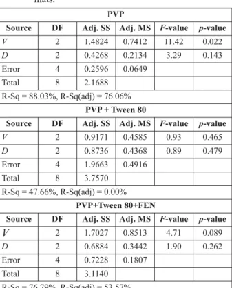
Table 4.ANOVA table of fiber diameters of the studied fiber mats.
PVP
Source DF Adj. SS Adj. MS F-value p-value
V 2 1.4824 0.7412 11.42 0.022
D 2 0.4268 0.2134 3.29 0.143
Error 4 0.2596 0.0649
Total 8 2.1688
R-Sq = 88.03%, R-Sq(adj) = 76.06%
PVP + Tween 80
Source DF Adj. SS Adj. MS F-value p-value
V 2 0.9171 0.4585 0.93 0.465
D 2 0.8736 0.4368 0.89 0.479
Error 4 1.9663 0.4916
Total 8 3.7570
R-Sq = 47.66%, R-Sq(adj) = 0.00%
PVP+Tween 80+FEN
Source DF Adj. SS Adj. MS F-value p-value
V 2 1.7027 0.8513 4.71 0.089
D 2 0.6884 0.3442 1.90 0.262
Error 4 0.7228 0.1807
Total 8 3.1140
R-Sq = 76.79%, R-Sq(adj) = 53.57%
The regression can be written as Equation (1):
(1) According to the model, there was a decrease in fiber size with increasing voltage (negative coefficient for V), while fiber size increases with the increasing dis- tance (positive coefficient for D). The contour plot can be seen in Figure 3a. The darkest blue color represents the smallest fibers (d< 1.5 μm), while the darkest
green shows the region in which the largest fibers (d> 3 μm) are to be produced. It can be seen that crossing the plot in a path parallel to the V axis (from low to high V) at any given D, the green color gets lighter, and the blue gets darker. This indicates that the average fiber size continuously decreases as the applied voltage is increased. At the same time, there are sections parallel to the Daxis, where the colors transition from dark to light blue and light to dark green, showing that the fibers got thicker as the
. . .
d=2 89 0 0495- V+0 0889D
Figure 2.SEM images at 100× and at 2000× magnification of samples: a), b) P_D10_V45, c), d) P/T_D10_V45 and e), f) P/T/F_D10_V45. Electrospinning conditions D= 10 cm and V= 45 kV.
electrode-collector distance increased. The correla- tion is much weaker for D, as a large portion of the plot (V= 28–40 kV) has sections with 1–2 hues only.
An explanation of this phenomenon is that higher V between the electrode and the collector at a set D creates a stronger electric field. Higher voltage
increases the volumetric charge density in the solu- tion [43], which most probably leads to stronger Coulomb forces that stretch the fibers (repulsive forces within the jet and attractive forces between the collector and jet). The narrowing of the Taylor cone at higher charge density also causes thinner jets Figure 3.a) Contour plot of the linear model for electrospun PVP fiber diameters as a function of voltage (V) and electrode- collector distance (D). b), c) Main effect plots of the V(b) and D(c) for the PVP+Tween 80 fiber size. d), e) Main effect plots of the V(d) and D(e) for the PVP+Tween 80+FEN fiber size.
[44] (although some reported thicker jets at higher charge density [45]). Experimental data showed that at higher charge densities, thinner fibers were pro- duced [46, 47]. In several studies, as the voltage was increased, fiber size decreased [48–50], with some exceptions [51].
The role of the Dis more complicated as additional effects come into play. On the one hand, a higher D value permits more time for the fibers to elongate, although this process is limited by the drying of the fibers [52]. Once most of the solvent evaporates, the viscosity of the fiber medium becomes very high, and the electric forces cannot overcome the viscoelas- tic forces anymore. At this point, the elongation of the fibers comes to a stop [53]. Thus, it is to be ex- pected that more Dresults in thinner fibers only when drying is not the limiting factor. On the other hand, at a given Vthe strength of the electric field [V/m] is inversely proportional to the D(when modeled with a uniform field). This also means a lower volumetric charge density [43]. In summary, the D has some- what the opposite effect of the V. The published data contains mixed results, some showing larger [54] or smaller diameters [51] at an increased distance, and in some cases the effect was not significant [50].
The correlation that existed in the case of the pure PVP solution disappeared with the addition of Tween 80. The p-values of the V(0.465) and the D (0.479) were much higher than 0.05, indicating that neither of the two had a statistically significant effect on the fiber size. In some cases, the absence of statis- tical significance for factor effects is not a problem as it provides robustness to the system; however, in our case, the main effects of both the voltage (from 2.3 to 3.1 μm, 33% increase from min to max, Figure 3b) and distance (from 2.5 to 3.2 μm, 27% from min to max, Figure 3c) seemed substantial. When the spread of the data is factored in, we can see that it is not im- plausible that these results could have occurred by random chance. Looking at the raw data (Table 3), samples containing PVP and Tween 80, there is a lack of consistency in the trends, i.e., at D= 10 cm as Vincreased from 25 to 45 kV, the average fiber di- ameter increased from 2.2 to 2.7 μm; but then at D= 13 cm the trend got reversed, and the average fiber size decreased from 3.3 to 2.1 μm as the voltage got higher. At D= 16 cm, the trend changed once again, V= 35 kV yielding the smallest size, while 25 kV the largest. Compared to the mean average values (between 2.5 and 3.2 μm) and the fluctuation within
the main effect plot (0.68 μm), the spread of the means for a given D was large (1.24 μm at D= 13 cm and 1.74 μm at D= 16 cm). In light of this in- terpretation, those seemingly large main effect val- ues become less meaningful. The same commentary can be applied to the D vs. fiber size plot in Figure 3c.
The role of the Tween 80 was to help dissolve the FEN, but as an adverse effect it changed other prop- erties of the solution as well. Tween 80 and other polysorbates are amphiphilic molecules used mainly as surface-active agents. The concentration of the Tween 80 was 6.5 wt% in the formulation, but when we exclude the solvent, it was actually 17.3% of the total solute mass. Tween 80 contains an oleic acid chain, and at this concentration, it is possible that a low degree phase separation occurred in the solution, causing the erratic behavior of the electrospinning process. To support this claim, further studies are needed.
In order to double-check whether the model was cor- rectly chosen, a quadratic model based on the central composite design was created for the P\T samples in addition to the linear regression model. Table 5 con- tains the ANOVA table of the quadratic model. The analysis showed that none of the linear, square, and interaction terms were statistically significant, all having p-values larger than 0.34. This can be inter- preted as there was no problem with the linear model, but rather the observed phenomena occurred ran- domly.
The data analysis for samples containing PVP, Tween 80 and FEN (P/T/F), the p-value of both the voltage and the distance were higher than 0.05;
however, the voltage effect was significant in the 90% confidence interval with its 0.089 p-value (Table 4). The main effect plot showed a 44% in- crease from the lowest to the highest value for the Table 5.ANOVA table of fiber diameters of the
PVP+Tween 80 fiber mats belonging to the quad- ratic model.
Source DF Adj. SS Adj, MS F-value p-value Regression 5 1.8691 0.3738 0.59 0.715
V 1 0.1233 0.5305 0.84 0.426
D 1 0.6936 0.0768 0.12 0.750
V·V 1 0.7938 0.7938 1.26 0.343
D·D 1 0.1800 0.1800 0.29 0.630
V·D 1 0.0784 0.0784 0.12 0.747
Residual error 3 1.8879 0.6293
Total 8 3.7570
R-Sq = 49.75%, R-Sq(adj) = 0.00%
voltage (Figure 3d), while the mean distance in- creased by 22% (Figure 3e). The most stable condi- tion for creating the FEN-loaded fibers was at 45 kV at any distance. Not only the average fiber size was almost identical for all three distances, but it yielded both the smallest fiber sizes (~2.2 μm) and the nar- rowest size distribution (~0.7 μm). In addition, the fiber morphology did not show any beading at all.
3.2. DSC results
On the DSC thermogram, the crystalline nature of the active pharmaceutical ingredient (API), FEN, can be observed, as characterized by its melting en- dotherm at 85.6 °C (Figure 4). The thermogram of PVP shows a broad, endothermic event, below 100 °C, which can be attributed to the dehydration
of the polymer [55]. The melting endotherm could not be observed on the thermogram of FEN-loaded microfibers, which could indicate at least a partial amorphization of the active; however, this event could also be masked by the broad dehydration event of the fiber-forming polymer.
3.3. UV-Vis spectroscopy results
The incorporation of the API into the fibers was tracked by UV spectroscopy. Comparative, overlaid UV spectra of solutions containing the active sub- stance and microfibrous mats are presented in Fig- ure 5. The obtained spectra are similar, both showing λmaxvalues characteristic for FEN (287 nm). Differ- ences can be observed in the low UV region, where higher absorption was observed for the microfibers.
This can be attributed mainly to the matrix compo- nents of the obtained microfibers. Drug loading was determined by UV spectroscopy at 287 nm, based on a calibration curve. The FEN content of the elec- trospun fiber mat was calculated using 3 replicates to be 5.31±0.02 w/w% (weight % of FEN with re- spect to the weight of the solid dispersion containing FEN, Tween 80, and PVP), which corresponds to 82.97±0.31% of the calculated, theoretical FEN con- tent. (6.4 w/w%).
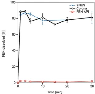
3.4. In vitrodissolution studies
Comparative in vitro dissolution studies were per- formed in water (Figure 6), as this medium proved Figure 4.DSC thermograms of FEN, PVP, and FEN-loaded
microfibers.
Figure 5.Overlaid UV spectra recorded for solutions con- taining FEN (red trace) and FEN-loaded microfibers (blue trace).
Figure 6.Comparative in vitrodissolution profiles obtained in water for micronized FEN (red trace), FEN- loaded microfibers obtained by corona-electro- spinning (black trace), and the earlier reported SNES setup (blue trace).
to be more discriminating in our earlier SNES study [25]. Indeed, as observed from the obtained dissolu- tion studies, in the case of the micronized active, only 2% was dissolved in 30 minutes. The microfi- brous formulations showed rapid disintegration and almost instantaneous release of the active ingredient.
The obtained results proved that the incorporation of the API in the microfibrous systems dramatically en- hanced dissolution. The obtained results are in line with our earlier report and underline the possibility of a quantitative leap in the production of drug- loaded microfibers, without compromising the qual- ity and performance of the product.
4. Conclusions
In conclusion, we can say that we have successfully produced FEN loaded PVP fiber mats using the newly reported, high throughput corona-electrospin- ning method. The produced fibers are randomly ori- ented, cylindrical and smooth-surfaced, with fiber diameters ranging from 1.4 to 4 μm. The statistical analysis indicates that the applied voltage has a sig- nificant effect on the fiber diameter when PVP alone is present in the solution, however when Tween 80 and FEN is introduced to the solution, none of the co- rona-electrospinning process parameters have a sig- nificant effect on the fiber diameter. The optimal con- dition to produce FEN-loaded fibers was at 45 kV;
the distance did not have much effect. The dissolu- tion studies show that the drug release from the fiber mats produced by the scale-up method, corona-elec- trospinning, is similar to that of the ones produced by the SNES method. This result, with the approxi- mately 2 times larges fiber diameter, indicates that the dissolution of FEN is not influenced by the fiber di- ameter when it is less than 3 μm. Only 2% of the mi- cronized FEN dissolved in 30 minutes, whereas ap- proximately 40 times higher release was observed from the FEN loaded PVP fiber mats. This could pave the way for electrospun FEN-loaded microfi- brous mat solid dispersions to treat dyslipidemia.
The presented results suggest that corona-electro- spinning has a potential application as a scale-up al- ternative to produce drug-loaded fiber mats.
Acknowledgements
The authors would like to thank the support for this project to the Domus Grant of the Hungarian Academy of Sciences.
Kolos Molnár would like to thank the János Bolyai Scholar- ship of the Hungarian Academy of Sciences and by the ÚNKP-20-54 New National Excellence Program of the Min- istry for Innovation and Technology for their kind support.
References
[1] Jermain S. V., Brough C., Williams R. O.: Amorphous solid dispersions and nanocrystal technologies for poor- ly water-soluble drug delivery – An update. Internation- al Journal of Pharmaceutics, 535, 379–392 (2018).
https://doi.org/10.1016/j.ijpharm.2017.10.051
[2] Boyd B. J., Bergström C. A. S., Vinarov Z., Kuentz M., Brouwers J., Augustijns P., Brandl M., Bernkop- Schnürch A., Shrestha N., Préat V., Müllertz A., Bauer- Brandl A., Janninj V.: Successful oral delivery of poorly water-soluble drugs both depends on the intraluminal behavior of drugs and of appropriate advanced drug de- livery systems. European Journal of Pharmaceutical Sciences, 137, 104967/1–104967/27 (2019).
https://doi.org/10.1016/j.ejps.2019.104967
[3] Lipinski C. A.: Drug-like properties and the causes of poor solubility and poor permeability. Journal of Phar- macological and Toxicological Methods, 44, 235–249 (2000).
https://doi.org/10.1016/S1056-8719(00)00107-6
[4] Keserü G. M., Makara G. M.: The influence of lead dis- covery strategies on the properties of drug candidates.
Nature Reviews Drug Discovery, 8, 203–212 (2009).
https://doi.org/10.1038/nrd2796
[5] Hann M. M.: Molecular obesity, potency and other ad- dictions in drug discovery. in ‘Multifaceted roles of crys- tallography in modern drug discovery’ (eds.: Scapin G., Patel D., Arnold E.) Springer, Dorbrecht, 183–196 (2015).
https://doi.org/10.1007/978-94-017-9719-1_14
[6] Merrill P.: Finding solutions – Creatively. Quality Progress, 50, 44–46 (2017).
[7] Ellenberger D., O’Donnell K. P., Williams R. O.: Opti- mizing the formulation of poorly water-soluble drugs.
in ‘Formulating poorly water soluble drugs’ (eds.:
Williams R. O., Watts A. B., Miller D. A.) Springer, Cham, 41–120 (2016).
https://doi.org/10.1007/978-3-319-42609-9_2
[8] Rams-Baron M., Jachowicz R., Boldyreva E., Zhou D., Jamroz W., Paluch M.: Amorphous drug solubility and absorption enhancement. in ‘Amorphous drugs’ (eds.:
Rams-Baron M., Jachowicz R., Boldyreva E., Zhou D., Jamroz W.) Springer, Cham, 41–68 (2018).
https://doi.org/10.1007/978-3-319-72002-9_3
[9] Sebe I., Szabó P., Kállai-Szabó B., Zelkó R.: Incorpo- rating small molecules or biologics into nanofibers for optimized drug release: A review. International Journal of Pharmaceutics, 494, 516–530 (2015).
https://doi.org/10.1016/j.ijpharm.2015.08.054
[10] Yu D-G., Li J-J., Williams G. R., Zhao M.: Electrospun amorphous solid dispersions of poorly water-soluble drugs: A review. Journal of Controlled Release, 292, 91–110 (2018).
https://doi.org/10.1016/j.jconrel.2018.08.016
[11] Jindal A., Puskas J. E., McClain A., Nedic K., Luebbers M. T., Baker Jr J. R., dos Santos B. P., Camassola M., Jennings W., Einsporn R. L., Leipzig N. D.: Encapsu- lation and release of Zafirlukast from electrospun poly- isobutylene-based thermoplastic elastomeric fiber mat.
European Polymer Journal, 98, 254–261 (2018).
https://doi.org/10.1016/j.eurpolymj.2017.11.012
[12] Szabó P., Sebe I., Stiedl B., Kállai-Szabó B., Zelkó R.:
Tracking of crystalline-amorphous transition of carvedilol in rotary spun microfibers and their formulation to orodispersible tablets for in vitrodissolution enhance- ment. Journal of Pharmaceutical and Biomedical Analy- sis, 115, 359–367 (2015).
https://doi.org/10.1016/j.jpba.2015.07.042
[13] Kim H. S., Yoo H. S.: Therapeutic application of elec- trospun nanofibrous meshes. Nanomedicine, 9, 517–
533 (2014).
https://doi.org/10.2217/nnm.13.224
[14] Hirsch E., Vass P., Démuth B., Pethő Zs., Bitay E., Andersen S. K., Vigh T., Verreck G., Molnár K., Nagy Zs. K., Marosi Gy.: Electrospinning scale-up and for- mulation development of PVA nanofibers aiming oral delivery of biopharmaceuticals. Express Polymer Let- ters, 13, 590–603 (2019).
https://doi.org/10.3144/expresspolymlett.2019.50
[15] Efimov A. E., Agapova O. I., Safonova L. A., Bobrova M. M., Parfenov V. A., Koudan E. V, Pereira F. D. A. S., Bulanova E. A., Mironov V. A., Agapov I. I.: 3D scan- ning probe nanotomography of tissue spheroid fibrob- lasts interacting with electrospun polyurethane scaffold.
Express Polymer Letters, 13, 632–641 (2019).
https://doi.org/10.3144/expresspolymlett.2019.53
[16] Xue J., Wu T., Dai Y., Xia Y.: Electrospinning and elec- trospun nanofibers: Methods, materials, and applica- tions. Chemical Reviews, 119, 5298–5415 (2019).
https://doi.org/10.1021/acs.chemrev.8b00593
[17] Taylor G. I.: Electrically driven jets. Proceedings of the Royal Society of London A: Mathematical and Physical Sciences, 313, 453–475 (1969).
https://doi.org/10.1098/rspa.1969.0205
[18] Bhardwaj N., Kundu S. C.: Electrospinning: A fascinat- ing fiber fabrication technique. Biotechnology Ad- vances, 28, 325–347 (2010).
https://doi.org/10.1016/j.biotechadv.2010.01.004
[19] Khan W. S., Asmatulu R., Ceylan M., Jabbarnia A.: Re- cent progress on conventional and non-conventional electrospinning processes. Fibers and Polymers, 14, 1235–1247 (2013).
https://doi.org/10.1007/s12221-013-1235-8
[20] Gergely A., Kántor J., Bitay E., Biró D.: Electrospin- ning of polymer fibres using recycled PET. Acta Mate- rialia Transylvanica, 2, 19–26 (2019).
https://doi.org/10.33924/amt-2019-01-04
[21] Kenawy E-R., Bowlin G. L., Mansfield K., Layman J., Simpson D. G., Sanders E. H., Wnek G. E.: Release of tetracycline hydrochloride from electrospun poly(eth- ylene-co-vinylacetate), poly(lactic acid), and a blend.
Journal of Controlled Release, 81, 57–64 (2002).
https://doi.org/10.1016/S0168-3659(02)00041-X
[22] Ding Y., Li W., Zhang F., Liu Z., Zanjanizadeh Ezazi N., Liu D., Santos H. A.: Electrospun fibrous architec- tures for drug delivery, tissue engineering and cancer therapy. Advanced Functional Materials, 29, 1802852/1–
1802852/35 (2019).
https://doi.org/10.1002/adfm.201802852
[23] Rosenson R. S.: Fenofibrate: Treatment of hyperlipi- demia and beyond. Expert Review of Cardiovascular Therapy, 6, 1319–1330 (2008).
https://doi.org/10.1586/14779072.6.10.1319
[24] Filippatos T., Milionis H. J.: Treatment of hyperlipi- daemia with fenofibrate and related fibrates. Expert Opinion on Investigational Drugs, 17, 1599–1614 (2008).
https://doi.org/10.1517/13543784.17.10.1599
[25] Sipos E., Csatári T., Kazsoki A., Gergely A., Bitay E., Szabó Z-I., Zelkó R.: Preparation and characterization of fenofibrate-loaded PVP electrospun microfibrous sheets. Pharmaceutics, 12, 612/1–612/10 (2020).
https://doi.org/10.3390/pharmaceutics12070612
[26] Guarino V., Iannotti V., Ausanio G., Ambrosio L., Lanotte L.: Elastomagnetic nanofiber wires by magnetic field assisted electrospinning. Express Polymer Letters, 13, 419–428 (2019).
https://doi.org/10.3144/expresspolymlett.2019.35
[27] Wu C. M., Chou M. H.: Acoustic–electric conversion and piezoelectric properties of electrospun polyvinyli- dene fluoride/silver nanofibrous membranes. Express Polymer Letters, 14, 103–114 (2020).
https://doi.org/10.3144/expresspolymlett.2020.10
[28] Vass P., Szabó E., Domokos A., Hirsch E., Galata D., Farkas B., Démuth B., Andersen S. K., Vigh T., Verreck G., Marosi Gy., Nagy Zs. K.: Scale-up of electrospin- ning technology: Applications in the pharmaceutical in- dustry. Wires Nanomedicine and Nanobiotechnology, 12, e1611/1–e1611/24 (2019).
https://doi.org/10.1002/wnan.1611
[29] Theron S. A., Yarin A. L., Zussman E., Kroll E.: Mul- tiple jets in electrospinning: Experiment and modeling.
Polymer, 46, 2889–2899 (2005).
https://doi.org/10.1016/j.polymer.2005.01.054
[30] Kim G., Cho Y-S., Kim W. D.: Stability analysis for multi-jets electrospinning process modified with a cylin- drical electrode. European Polymer Journal, 42, 2031–
2038 (2006).
https://doi.org/10.1016/j.eurpolymj.2006.01.026
[31] Liu Z., Zhao J., Zhou L., Xu Z., Xing J., Feng Q.: Re- cent progress of the needleless electrospinning for high throughput of nanofibers. Recent Patents on Nanotech- nology, 13, 164–170 (2019).
https://doi.org/10.2174/1872210513666190426151150 [32] Niu H., Wang X., Lin T.: Upward needleless electro-
spinning of nanofibers. Journal of Engineered Fibers and Fabrics, 7, 17–22 (2012).
https://doi.org/10.1177/155892501200702s03
[33] Jirsák O., Sanetrník F., Lukáš D., Kotek V., Martinová L., Chaloupek J.: Method of nanofibres production from a polymer solution using electrostatic spinning and a device for carrying out the method. CZ20032421A3, Czech Republic (2009).
[34] Li J., Gao F., Liu L. Q., Zhang Z.: Needleless electro- spun nanofibers used for filtration of small particles.
Express Polymer Letters, 7, 683–689 (2013).
https://doi.org/10.3144/expresspolymlett.2013.65
[35] Wang X., Niu H., Lin T., Wang X.: Needleless electro- spinning of nanofibers with a conical wire coil. Polymer Engineering and Science, 49, 1582–1586 (2009).
https://doi.org/10.1002/pen.21377
[36] Niu H., Lin T., Wang X.: Needleless electrospinning. I.
A comparison of cylinder and disk nozzles. Journal of Applied Polymer Science, 114, 3524–3530 (2009).
https://doi.org/10.1002/app.30891
[37] Lu B., Wang Y., Liu Y., Duan H., Zhou J., Zhang Z., Wang Y., Li X., Wang W., Lan W., Xie E.: Superhigh- throughput needleless electrospinning using a rotary cone as spinneret. Small, 6, 1612–1616 (2010).
https://doi.org/10.1002/smll.201000454
[38] Tang S., Zeng Y., Wang X.: Splashing needleless elec- trospinning of nanofibers. Polymer Engineering and Science, 50, 2252–2257 (2010).
https://doi.org/10.1002/pen.21767
[39] Molnár K., Nagy Zs. K.: Corona-electrospinning:
Needleless method for high-throughput continuous nano - fiber production. European Polymer Journal, 74, 279–
286 (2016).
https://doi.org/10.1016/j.eurpolymj.2015.11.028
[40] He H., Kara Y., Molnár K.: In situ viscosity-controlled electrospinning with a low threshold voltage. Macro- molecular Materials and Engineering, 304, 1900349/1–
1909349/10 (2019).
https://doi.org/10.1002/mame.201900349
[41] Farkas B., Balogh A., Cselkó R., Molnár K., Farkas A., Borbás E., Marosi Gy., Nagy Zs. K.: Corona alternating current electrospinning: A combined approach for in- creasing the productivity of electrospinning. Interna- tional Journal of Pharmaceutics, 561, 219–227 (2019).
https://doi.org/10.1016/j.ijpharm.2019.03.005
[42] Rošic R., Kocbek P., Baumgartner S., Kristl J.: Electro- spun hydroxyethyl cellulose nanofibers: The relation- ship between structure and process. Journal of Drug De- livery Science and Technology, 21, 229–236 (2011).
https://doi.org/10.1016/S1773-2247(11)50031-0
[43] Theron S. A., Zussman E., Yarin A. L.: Experimental investigation of the governing parameters in the elec- trospinning of polymer solutions. Polymer, 45, 2017–
2030 (2004).
https://doi.org/10.1016/j.polymer.2004.01.024
[44] Stanger J., Staiger M. P., Tucker N., Kirwan K.: Effect of charge density on the Taylor cone in electrospinning.
International Journal of Modern Physics B, 23, 1956–
1961 (2009).
https://doi.org/10.4028/www.scientific.net/SSP.151.54 [45] Thompson C. J., Chase G. G., Yarin A. L., Reneker D.
H.: Effects of parameters on nanofiber diameter deter- mined from electrospinning model. Polymer, 48, 6913–
6922 (2007).
https://doi.org/10.1016/j.polymer.2007.09.017
[46] Fong H., Chun I., Reneker D. H.: Beaded nanofibers formed during electrospinning. Polymer, 40, 4585–
4592 (1999).
https://doi.org/10.1016/S0032-3861(99)00068-3
[47] Angammana C. J., Jayaram S. H.: Analysis of the ef- fects of solution conductivity on electrospinning process and fiber morphology. IEEE Transactions on Industry Applications, 47, 1109–1117 (2011).
https://doi.org/10.1109/TIA.2011.2127431
[48] Amiraliyan N., Nouri M., Kish M. H.: Effects of some electrospinning parameters on morphology of natural silk-based nanofibers. Journal of Applied Polymer Sci- ence, 113, 226–234 (2009).
https://doi.org/10.1002/app.29808
[49] Beachley V., Wen X.: Effect of electrospinning param- eters on the nanofiber diameter and length. Materials Science and Engineering: C, 29, 663–668 (2009).
https://doi.org/10.1016/j.msec.2008.10.037
[50] Nasouri K., Bahrambeygi H., Rabbi A., Shoushtari A.
M., Kaflou A.: Modeling and optimization of electro- spun PAN nanofiber diameter using response surface methodology and artificial neural networks. Journal of Applied Polymer Science, 126, 127–135 (2012).
https://doi.org/10.1002/app.36726
[51] Li Q., Jia Z., Yang Y., Wang L., Guan Z.: Preparation and properties of poly (vinyl alcohol) nanofibers by electrospinning. in ‘2007 IEEE International Confer- ence on Solid Dielectrics, Winchester, England’ 215–
218 (2007).
https://doi.org/10.1109/ICSD.2007.4290790
[52] Tripatanasuwan S., Zhong Z., Reneker D. H.: Effect of evaporation and solidification of the charged jet in elec- trospinning of poly(ethylene oxide) aqueous solution.
Polymer, 48, 5742–5746 (2007).
https://doi.org/10.1016/j.polymer.2007.07.045
[53] Yarin A. L., Koombhongse S., Reneker D. H.: Bending instability in electrospinning of nanofibers. Journal of Applied Physics, 89, 3018/1–3018/9 (2001).
https://doi.org/10.1063/1.1333035
[54] Wang T., Kumar S.: Electrospinning of polyacryloni- trile nanofibers. Journal of Applied Polymer Science, 102, 1023–1029 (2006).
https://doi.org/10.1002/app.24123
[55] Sipos E., Kósa N., Kazsoki A., Szabó Z-I., Zelkó R.:
Formulation and characterization of aceclofenac-loaded nanofiber based orally dissolving webs. Pharmaceutics, 11, 417/1–417/11 (2019).
https://doi.org/10.3390/pharmaceutics11080417