1
COMBINING SIGNAL PRE-PROCESSING METHODS WITH BEAMFORMING FOR BROADBAND TURBOMACHINERY
APPLICATIONS
Kristóf Tokaji and Csaba Horváth
Department of Fluid Mechanics, Faculty of Mechanical Engineering Budapest University of Technology and Economics
4-6. Bertalan Lajos utca, Budapest, Hungary, 1111
ABSTRACT
This study investigates a novel method for separating apart the broadband and tonal components in beamforming maps. A possible method for separating apart the tonal and broadband noise sources is to post-process the beamforming maps, analyzing the beamforming maps and the spectrum of the beamforming peaks, manually separating the identified noise sources into categories. This separation process is quite subjective, as the locations of many dominant noise sources often overlap for both tonal as well as broadband noise generation mechanisms. A more objective method for separating apart noise sources is the pre-processing of microphone signals prior to beamforming, applying methods capable of separating apart the broadband and tonal components in the audio signals, which have been recorded by the individual microphones of the array. The combination of pre- processing the microphone signals in order to remove the tonal noise and beamforming the new signals results in a novel approach for the investigation of the broadband noise generation mechanisms. In this investigation a complex turbomachinery test case is looked at, namely counter-rotating open rotors, using phased array microphones and beamforming technology. Though applied here to counter-rotating open rotors, the method applicable to all turbomachinery cases.
1 INTRODUCTION
Broadband noise sources are often hidden below the plotted dynamic range in beamforming maps due to the large amplitudes of other tonal components. Multiple articles can be found in the literature, which aim to study the less significant noise sources of a given phenomenon, but to the best knowledge of the authors, no investigations have attempted the pre-processing of the microphone signals prior to applying beamforming. The authors themselves have rather applied a post-processing of the data until now, examining each noise source on the individual beamforming maps in order to determine whether they were resulting from tonal or broadband noise sources [1,2], going through a tedious and often subjective process in order to determine whether noise sources belong in the broadband or tonal groups. Even though no articles were
2
found which combine the pre-processing of microphone signals and beamforming, the pre- processing of microphone signals is an accepted method in acoustic measurement methods [3,4,5]. These methods can be used to manipulate the data in many ways, including the separation of the tonal and broadband components. In this article the combination of pre- processing microphone signals followed by beamforming is investigated, which leads to a novel approach for examining turbomachinery noise sources.
Turbomachinery noise often consists of tonal as well as broadband components. The frequency of the tonal components can be calculated based on rotational speeds and basic geometric information, such as number of blades. Therefore, typical components of tonal noise can often be identified in a spectrum with the help of such basic calculations. The broadband components, on the other hand, are present for a wide frequency range. One means of localizing noise sources and hence identifying the noise generation mechanisms of turbomachinery is the use of beamforming techniques [1,6]. In the case of Counter-Rotating Open Rotors (CROR), tonal components appear very densely spaced throughout the entire spectrum and the broadband components, which have smaller amplitudes, are therefore hidden in the background, but still play an important role in defining the noise character of CROR [1].
CROR are highly efficient aircraft engines and could provide a reasonable alternative to turbofan engines for certain categories of aircraft, which are at present the most often used type of aircraft engine. Prior to their widespread application, some technical problems must first be solved. One of these problems is the reduction of their noise emission levels [1,2,3,4,5,7,8].
Therefore, the noise generation mechanisms of CROR have to be investigated, understood, and eliminated. In this paper, a novel method for the investigation of the broadband noise sources of CROR configurations is proposed. It should not be forgotten that the pre-processing of microphone signals prior to applying beamforming methods is not restricted to CROR. The pre- processing method applied here is valid for all turbomachinery applications, as well as entirely different phenomena if other pre-processing methods are used.
2 MEASUREMENT SETUP
In this article CROR measurement data is used for demonstrating the method for separating the tonal and broadband components of turbomachinery noise. The measurements were carried out in the NASA Glenn Research Center 9×15 ft Low-Speed Wind Tunnel, mounting the investigated rotors on the Open Rotor Propulsion Rig [1,2]. The investigated blades are those of the F31/A31 historical baseline blade set [8]. The forward blade row of the design consists of 12 blades with a diameter of 0.652 m and a blade angle of 33.5°, while the aft rotor has 10 blades with a diameter of 0.630 m and a blade angle of 35.7°. The Mach number of the flow in the wind tunnel was Ma=0.2, while the angle-of-attack of the flow with regard to the test rig was 0°. The rotational speed was set to a standard day value of 5598 rpm. The test case investigated here is that of an uninstalled (standalone) CROR, without any installation equipment. Further details regarding the test set-up and the test matrix can be found in [1,2,8].
Acoustic measurements were carried out using the OptiNAV Array48 phased array microphone system (left side of Fig. 1) [9]. The signals from the 48 microphones were simultaneously recorded, using a sampling rate of 96 kHz and then processed using Sree’s method and Delay-and-sum beamforming in the frequency domain [10]. The cross-spectral matrices used during the processing of the data were made using a transform length of 4096, and 6 dB were subtracted from the results in order to account for the pressure doubling on the surface of the array. During the testing, the phased array was mounted in a cavity along the
3
southern wall of the wind tunnel facility directly across from the test rig. In order to remove the microphones from the flow, a Kevlar® fabric was tightly stretched over the opening of the cavity, leaving a gap between the fabric and the phased array. This technique has been developed and tested by others in [11] and [12], where the ability of the technology to improve the signal-to-noise ratio was demonstrated. The signal-to-noise ratio was further improved by using a long time series (45 s) and removing the diagonal of the cross-spectral matrix. During the measurements, the microphone array was located at a distance of 1.6 m from the center plane of the test rig, the plane under investigation, which can be considered to be in the acoustic far-field according to simulations carried out by Horváth et al. [1,2]. The measurement setup is shown on the right side of Fig. 1, with the Kevlar® window being located on the right hand side of the test rig in the figure.
Fig. 1. The Array48 system and its installation in the wall of the LSWT [1]
3 METHODS FOR SEPARATING APART THE TONAL AND BROADBAND NOISE SOURCES
3.1 Method based on the post-processing of the beamforming results
As discussed in the introduction, prior to this investigation, no pre-processing of the signals has been attempted before carrying out the beamforming process. Instead, in order to determine whether a noise source is a tonal or broadband noise source, the spectrum and the beamforming maps of the dominant noise sources of the investigated frequency bins have been used to categorize the noise sources [1]. For the CROR case investigated here, in accordance with the CROR literature [1,2,13,14,15], the tonal noise sources can be sorted into subgroups according to their noise generation mechanisms. The largest peaks on the beamforming maps, called from hereon as the Power Spectral Density (PSD) values of Beamforming peaks (BFpeaks), of an uninstalled CROR will most often be associated with rotating coherent noise sources. These tonal noise sources are localized to their Mach radii rather than their true source positions. Some of the rotating coherent noise sources are associated with interactions between neighboring rotating blade rows (Interaction tones), while others are associated with the repeated blade passing of the individual rotors (Blade Passing Frequency (BPF) tones). Therefore, these types of noise sources can appear in frequency bins associated with interaction tones XBPFF+YBPFA
and BPF tones XBPFF or YBPFA, where subscript F refers to the forward rotor and subscript A refers to the aft rotor, and X and Y are positive whole numbers. Unfortunately, it cannot be stated for certain that the dominant noise sources of the largest peaks of the spectrum appearing
4
in frequency bins associated with the BPF or interaction tones are those associated with the rotating coherent noise sources. As a result, it is necessary to investigate the locations of the noise sources on the beamforming maps. In that case, if the dominant noise source is localized to the Mach radius of the investigated rotating coherent noise source, then it is associated with it.
All rotating noise sources, which are not categorized as rotating coherent noise sources, belong to the group of the rotating incoherent noise sources. This group contains the broadband as well as the shaft order (once-per-rev) noise sources. Though both types of noise sources origin from a broadband noise generation mechanism, the shaft order noise sources appear as tonal peaks in the BFpeak spectrum. The reason for this is that the position of the viewer (microphone array) with respect to the source (located on individual blades) causes the broadband signal radiating from the noise source to appear stronger in the recorded microphone signals in a cyclic fashion, when the source moves past the array, which occurs once per every revolution (hence once-per-rev).
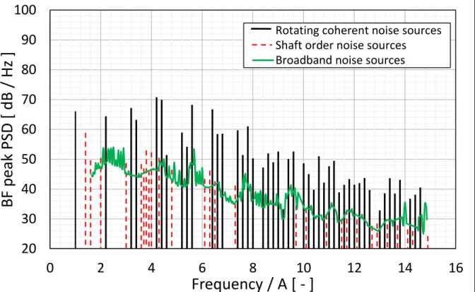
Taking the above described characteristics into consideration, the examination of the spectrum and beamforming maps makes it possible to determine the broadband or tonal nature and in some cases the generation mechanism of the dominant noise sources of the investigated frequency bins, and sometimes even the less significant noise sources as well. With the help of this sorting method, the tonal and the broadband spectra can be separated. The separated tonal and broadband components for the case of an uninstalled CROR can be seen in Fig. 2.
Fig. 2. Spectrum of the BFpeak values for an uninstalled CROR test case depicting the tonal and broadband components that were identified using the method of post-processing of beamforming maps.
20 30 40 50 60 70 80 90 100
0 2 4 6 8 10 12 14 16
BF peak PSD [ dB / Hz ]
Frequency / A [ - ]
Rotating coherent noise sources Shaft order noise sources Broadband noise sources
5
3.2 Method based on the pre-processing of microphone signals
Though not yet implemented in beamforming methods, there are methods for separating apart the tonal and broadband components of turbomachinery noise. As an example, Sree and Stephens have developed a signal processing technique, which successfully separates apart the tonal and broadband portions of the signal of a recorded audio file for the noise of various turbomachinery configurations [3,4]. The technique carries out operations on segments of the recorded signal, which are one revolution in length. For turbomachinery that consists of a single rotor, the average of these segments is equal to the tonal component of the signal. If this average (the tonal component) is subtracted from a phase aligned segment of the microphones signal, it results in the broadband component. This averaging method is not appropriate for the double rotor configurations, because of the jitter or deviation of rotor speed or random phase shifts in measured data [4]. Therefore, it cannot be used for the investigation of the noise of a CROR.
Sree and Stephens improved their signal process technique for configuration with double blade set and it is described in the following paragraph.
The latest method of Sree and Stephens [3] is capable of separating out a broadband signal from the noise of a CROR, which is statistically equivalent with the original broadband noise component. The applied technique consists of the following steps: 1 – Apply a high pass and low pass filter to the recorded signal in order to concentrate on the frequency range which is relevant for the given CROR. 2 – Split the signal into one revolution long segments. 3 – Phase adjust the neighboring segment pairs in order to reach a maximum correlation. 4 – Subtract the segment pairs from one another according to Eq. (1), where 𝑥 is the first segment and 𝑦 is the second segment of the pair and 𝑧′ is the new broadband component.
𝑧
′=
𝑥−𝑦√2 (1)
In Eq. (1), segments 𝑥 and 𝑦 can be separated into tonal (𝑥̅ and 𝑦̅) and broadband (𝑥′ and 𝑦′) components. The tonal components of the two signal segments are equal because the tonal noise generation mechanisms do not change in time (𝑥̅ = 𝑦̅). Therefore, subtracting the one original segment from the other is the same as subtracting the one broadband component from the other (𝑥 − 𝑦 = 𝑥̅ + 𝑥′− 𝑦̅ − 𝑦′ = 𝑥′− 𝑦′). In order to guarantee that 𝑧′ is statistically equivalent with the original broadband noise component, it is necessary to divide by √2. Using the method of Sree and Stephens, the spectrum of the broadband noise component can be created and therefore the broadband noise component can be investigated separately from that of the tonal component.
3.3 Combination of the method for pre-processing the microphone signals with beamforming
According to conventional time domain based beamforming methods, noise sources are localized on the beamforming maps if the RMS value of the sum of the phase and amplitude corrected signals of all the microphones in the array is large in a given point. In order to avoid the misinterpretation of sidelobes as noise sources, a lower limit is often set, below which the beamforming values are not investigated [10]. If the original broadband segments (𝑥′ and 𝑦′) and the new generated broadband segment (𝑧′) are statistically equivalent (the RMS values are equivalent) then the beamforming maps of 𝑧′ will be equal to 𝑥′ and 𝑦′. Therefore, the beamforming maps of the generated broadband noise components show the actual beamforming maps of the actual broadband noise components. Equation (2) and (3) show the requirement of
6
the broadband noise source localization on the beamforming maps for the original broadband component. Equation (4) shows the same requirement for the generated 𝑧′ broadband signal.
𝑥
1′= 𝑥′ ̂ ;
2 (2)𝑦
1′= 𝑦′ ̂
2 (3)𝑧
1′=
𝑥1−𝑦1√2
=
𝑥̂−𝑦2 ̂2√2
=
𝑥2−𝑦2̂ = 𝑧
√2̂
2′ (4)Where 𝑥1′ is the broadband component of the first segment of recorded signal of the microphone No. 1 and 𝑦1′ belongs to the second segment. 𝑥′̂2 and 𝑦′̂2 are the same signal components of microphone No. 2., after amplitude and phase correction. If Eq. (2) and (3) are true, the RMS value in the beamforming calculations has a large value and there will be a noise source localization on the beamforming maps. 𝑧1′ is a segment of the generated broadband component of microphone No. 1. and 𝑧̂2′ is the same segment of the signal for microphone No. 2. after phase and amplitude correction. According to Eq. (1), 𝑧1′ can be expressed using 𝑥1 and 𝑦1. Equation (2) and (3) can also be applied to the original segments (which include the tonal components), as seen in Eq. (4). Therefore, it can be concluded that in order for noise sources to be localized on the beamforming maps, the segments of the original signals of microphones No. 1. and 2. must be equal (after phase and amplitude correction), as is the requirement for noise source localization without pre-processing. As seen in Eq. (4), the amplitude and phase correction can be carried out after the subtraction. Therefore, it is easy to see that the requirements for noise source localization are satisfied for the generated broadband signals, which have been created from the original microphone signals. Therefore, the beamforming maps of 𝑧1′, and the original broadband noise components (𝑥′ and 𝑦′) will be equal. It can therefore be concluded that the broadband components of the noise of a CROR can be investigated using the modified microphone signals created using the method of Sree and Stephens [3]. Applying the method to the signals of all the microphones of the beamforming array, the investigation of the dominant broadband noise sources of a CROR (and any turbomachinery) becomes possible.
4 RESULTS
4.1 Post-processing results
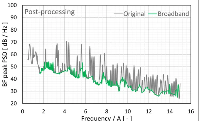
The post-processing results have already been investigated in [1,2] with the method introduced in section 3.1. The examined frequency range is divided into 19.1 Hz wide bands and the level values of the BFpeak are calculated to PSD values. By investigating the BFpeak spectrum and the dominant noise sources on the beamforming maps, the dominant noise sources of the frequency bands can be categorized as tonal or broadband noise sources. The removal of the bands which are dominated by tonal noise sources, results in the broadband spectrum, which can be seen in Fig. 3.
7
Fig. 3. The spectrum of the original signal (grey) and the broadband component (green) resulting from the post-processing of beamforming maps
The spectrum in Fig. 3 shows the amplitude values of the BFpeak spectrum which are associated with the broadband components. Therefore, approximately only half of the frequency bins have amplitude values. There are some peaks in the broadband spectrum, because the separation method is very subjective and in some cases it is impossible to distinguish the broadband noise sources from the tonal noise sources according to the beamforming maps.
4.2 Pre-processing results
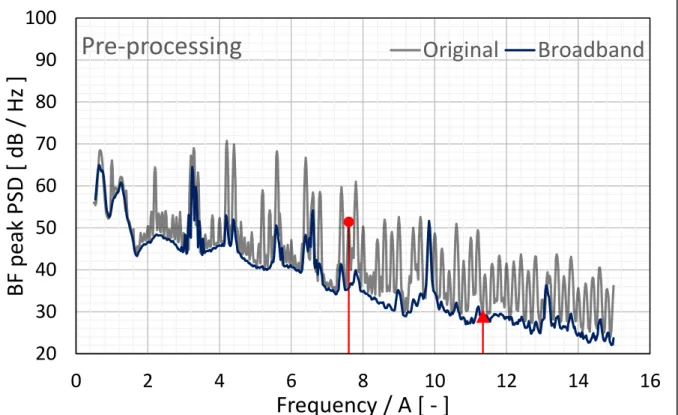
The signal processing method of Sree and Stephens has been developed for separating apart the tonal and the broadband components of the noise signal for turbomachinery applications. It can be used efficiently for CROR measurement data [3,4]. The method removes the tonal component from the recorded signal of a microphone, and therefore the broadband signal can be extracted. As can be seen in Fig. 4, most of the tonal peaks have disappeared.
20 30 40 50 60 70 80 90 100
0 2 4 6 8 10 12 14 16
BF peak PSD [ dB / Hz ]
Frequency / A [ - ]
Post-processing Original Broadband
8
Fig. 4. Spectrum of the original signal (grey) and the broadband component (blue) created by pre- processing the microphone signals. The red markers show the frequency bands of the beamforming maps presented in section 4.4
Fig. 4 shows that some peaks have not disappeared with the pre-processing of the signals. In other words, there are tonal peaks in the spectrum of the modified signals, which have approximately the same amplitude values for the cases with and without pre-processing. These peaks belong to a whistle which was fixed to the configuration. These peaks appear at relative frequencies of 3.2, 6.4, 9.6, and 13.8. The method of Sree and Stephens only removes the tonal peaks which are linked to the rotational frequencies of the axes. The frequency of the whistle does not depend on the rotation, and therefore it remains in the signal.
Other peaks have smaller amplitude values than in the original spectrum. This can allude to non-revolution dependent noise sources or to limitations in the method of Sree and Stephens.
The beamforming maps of these frequency bins need to be further investigated together with the results achieved by post-processing the beamforming maps.
4.3 Comparison of the spectral results
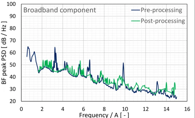
The advantage of the method of Sree and Stephens over the post-processing method is in the way the separation process categorizes the tonal and broadband components. Figure 5 presents a comparison between pre- and post-processing spectral results. The post-processing spectrum appears to contain many more tonal peaks. In the pre-processing spectrum, most of the tonal peaks have disappeared, but the peaks associated with the whistle are still present, while the post-processing method removed them.
20 30 40 50 60 70 80 90 100
0 2 4 6 8 10 12 14 16
BF peak PSD [ dB / Hz ]
Frequency / A [ - ]
Pre-processing Original Broadband
9
Fig. 5. Comparison of the BF peak spectra in the case of the post- and pre-processing methods
A great advantage of the pre-processing method is that it results in a continuous BFpeak spectrum. There are amplitude values for every frequency bin, while the broadband spectrum of the post-processing method has amplitude values only for the frequencies, which were dominated by the broadband noise component in the case of the original signal. In the figures these bins have been connected using a continuous line in order to help visualize approximately where the broadband spectrum would lay. Therefore, the pre-processing method makes possible the investigation of the broadband noise sources even in those frequency bins, which originally contain dominant tonal noise sources. The noise of a CROR consists of numerous tonal peaks, therefore this examination method provides a novel approach in the investigation of the broadband noise component.
The results show that the best way to investigate the noise components of turbomachinery is the combination of the pre- and post-processing methods. On the one hand the questionable noise sources of the original signal can be categorized much more easily by generating the broadband signal. If the tonal peaks on the BFpeak spectrum disappear after applying the method of Sree and Stephens, then the noise sources originate from tonal noise generation mechanisms. On the other hand, the tonal peaks remaining in the modified signal need to be investigated and categorized in the same way as done in the method which applies a post- processing of the beamforming maps and the spectrum. In this way, the peaks, which origin from tonal noise generation mechanisms and remain in the broadband spectrum can be removed.
4.4 Beamforming maps
The method based on the post-processing of beamforming maps, consists of the examination of the beamforming maps of the original noise signal. This method is very useful in the
20 30 40 50 60 70 80 90 100
0 2 4 6 8 10 12 14 16
BF peak PSD [ dB / Hz ]
Frequency / A [ - ]
Broadband component Pre-processing
Post-processing
10
investigation of the dominant tonal noise sources, because they have large amplitudes and well- defined locations on the beamforming maps. The broadband components generally have lower amplitudes and an uncertain or smeared distribution on the beamforming maps. The pre- processing of microphone signals removes the tonal component from the signal and results in broadband components, which have the same beamforming maps as the broadband components of the original signal. Herein, two typical beamforming map pairs are shown. The first beamforming map pair belongs to a frequency band, which contains a rotating coherent noise source on the beamforming map of the original signals (see Fig. 6). The second beamforming map pair belongs to a frequency bin, which contains a dominant broadband noise source according to the beamforming map of the original signals (see Fig. 7). Therefore, this frequency bin is categorized as broadband by both the pre-processing as well as the post-processing methods.
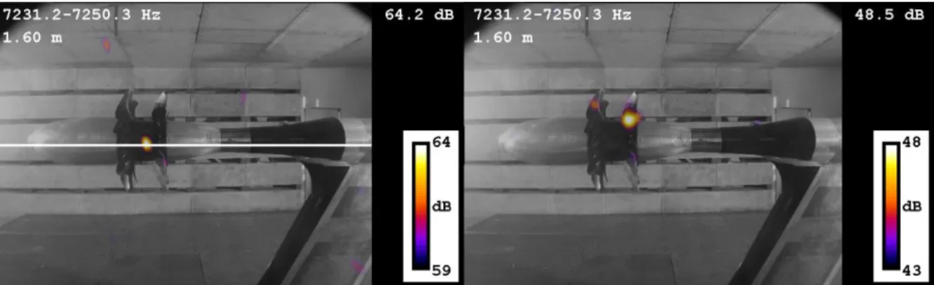
Fig. 6. The beamforming maps of the frequency bin between 7231.2 and 7250.3 Hz in the case of the original signals (left) and the pre-processed signals (right)
On the left side of Fig. 6, the beamforming map of the original signal can be seen. The white horizontal line shows the location of the expected rotating coherent noise source (according to Mach radii calculations [1,2]). The noise source localization on the beamforming map is located on this line, and therefore it can be stated that it is an interaction tone from the group of rotating coherent noise sources. The frequency bin of this noise source is shown by a red dot in Fig. 4.
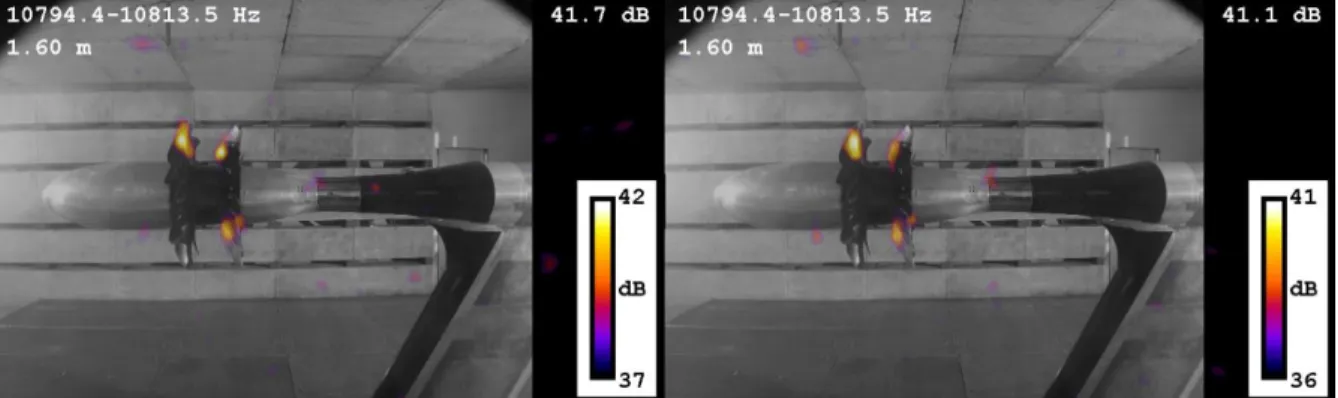
On the right side of Fig. 6, the beamforming map of the pre-processed signals is shown. The location of the dominant noise source has changed as compared to the dominant noise source of the original signals. It should also be noticed that the largest amplitude of the investigated frequency bin has decreased more than 15 dB. In accordance with the former sections, this beamforming map belongs to the broadband component of the investigated bin. In Fig. 7, the beamforming maps are quite similar. Both the left and the right hand side figures show the beamforming map of the broadband component. The frequency bin of this noise source is shown by a red triangle in Fig. 4. In this frequency bin, the broadband component was the dominant noise in the original signals, and therefore the post-processing method considered it as a broadband noise source. There was no tonal component in this frequency range, and therefore the beamforming of the modified signals resulted in a similar beamforming map.
11
Fig. 7. The beamforming maps of the frequency bin between 10794.4 and 10813.5 Hz in the case of the original signals (left) and the pre-processed signals (right)
According to the spectral and beamforming map results, the pre-processing method is very useful in the investigation of the broadband noise component of CROR. The combination of pre- and post-processing methods provides a quite efficient examination technique.
5 CONCLUSIONS
In this paper, the advantages associated with using a pre-processing of microphone signals before beamforming has been examined for a turbomachinery test case. This was necessary, since the broadband components of the generated noise were hard to examine due to their low amplitude values, as compared to those of the tonal components. Separation methods applied in the past, e.g. post processing of beamforming maps, were often rather subjective and were not able to provide continuous spectral results. Pre-processing methods, such as the method developed by Sree and Stephens, can generate a broadband signal from a recorded signal by removing the tonal components. Using this technique, the recorded signals of all the microphones of a microphone array can be modified/filtered. Due to the statistical equivalence between the generated broadband signal and the broadband component of the original signal, beamforming of the generated signal results in the beamforming maps and the beamforming peak spectrum of the broadband component of the noise of the investigated turbomachinery test case. The technique removed all the tonal peaks originating from the revolution frequency. The beamforming maps show significant differences from the beamforming maps of the original signal in the frequency bins where originally a tonal noise source was the most dominant. In the case of an originally broadband bin, the beamforming maps are quite similar, which verifies the validity of the beamforming results of the pre-processed signals. This investigation has shown that applying pre-processing methods in beamforming helps in making the results less ambiguous, especially when combining pre- and post-processing methods in the investigation of turbomachinery applications.
ACKNOWLEDGEMENTS
The testing of the CROR was funded by the Environmentally Responsible Aviation Project of the NASA Integrated Systems Research Program and the Fixed Wing Project of the NASA Fundamental Aeronautics Program. The present investigation was supported by the Hungarian National Research, Development and Innovation Center under contract Nos. K 119943 and the János Bolyai Research Scholarship of the Hungarian Academy of Sciences. The work relates to the scientific programs “Development of quality-oriented and harmonized R+D+I strategy
12
and the functional model at BME” (Project ID: TÁMOP-4.2.1/B-09/1/KMR-2010-0002) and
“Talent care and cultivation in the scientific workshops of BME” (Project ID: TÁMOP-4.2.2/B- 10/1-2010-0009).
REFERENCES
[1] Cs. Horváth, “Beamforming Investigation of Dominant Counter-Rotating Open Rotor Tonal and Broadband Noise Sources.” AIAA Journal, 53(6), 1602-1611, 2015.
[2] Cs. Horváth, E. Envia and G. G. Podboy, “Limitations of Phased Array Beamforming in Open Rotor Noise Source Imaging.” AIAA Journal, 52(8), 1810-1817, 2014.
[3] D. Sree and D. B. Stephens, “Improved separation of tone and broadband noise components from opne rotor acoustic data.” Aerospace, 3(3), 29; 2016.
doi:10.3390/aerospace3030029
[4] D. Sree, “A novel signal processing technique for separating tonal and broadband noise components from counter-rotating open-rotor acoustic data.” International Journal of Aeroacoustics, 12(1-2), 169-188, 2013.
[5] D.B. Stephens and E. Envia, “Acoustic Shielding for a Model Scale Counter-rotation Open Rotor.” 17th AIAA/CEAS Conference, Portland, Oregon, USA, June 5-8, 2011.
[6] P. Sijtsma, S. Oerlemans and H. Holthusen, “Location of rotating sources by phased array measurements.” AIAA-2001-2167, 2001. 7th AIAA/CEAS Aeroacoustics Conference, Maastricht, Netherlands, 28-30 May, 2001.
[7] M. D. Bowles, ““Apollo” of Aeroacoustics: NASA’s Aircraft Energy Efficiency Program 1973-1987.” NASA Headquarters, Washington, D.C., USA, 113-140, 2010.
[8] D. E. Van Zante, J. A. Gazzaniga, D. M. Elliott, et al., “An Open Rotor Test Case:
F31/A31 Historical Baseline Blade Set.” 20th International Symposium on Airbreathing Engines, Gothenburg, Sweden, ISABE 2011-1310, 2011.
[9] Optinav Inc., Array 48, http://www.optinav.info/Array48.pdf, 2017.
[10] T. J. Mueller, “Aeroacoustic Measurements.” Springer-Verlag, Berlin, Germany, 2002.
[11] S. M. Jaeger, W. C. Horne and C. S. Allen, “Effect of Surface Treatment on Array Microphone Self-Noise.” AIAA 2000-1937, 6th AIAA/CEAS Aeroacoustics Conference and Exhibit, Lahaina, Hawaii, USA, 2000.
[12] V. Fleury, L. Coste and R. Davy, “Optimization of Microphone Array Wall Mountings in Closed-Section Wind Tunnels.” AIAA Journal, 50(11), 2325-2335, 2012.
[13] B. Parry and D. G. Crighton, “Prediction of Counter-Rotation Propeller Noise.” AIAA- 89-1141, AIAA 12th Aeroacoustics Conference, San Antonio, TX, USA, 1989.
[14] D. B. Hanson, “Noise of counter-rotation propellers.” AIAA-84-2305, 9th AIAA Aeroacoustics Conference, Williamsburg, VA, USA, 1984.
[15] E. Envia, “Open Rotor Aeroacoustic Modelling.” CMFF 027-1040, 15th International Conference on Fluid Flow Technologies, Budapest, Hungary, 2012.
![Fig. 1. The Array48 system and its installation in the wall of the LSWT [1]](https://thumb-eu.123doks.com/thumbv2/9dokorg/1429467.121486/3.892.130.768.364.617/fig-array-installation-wall-lswt.webp)