DOCTORAL THESIS
HUNGARIAN ACADEMY OF SCIENCES
BLADE SWEEP APPLIED TO AXIAL FLOW FAN ROTORS OF CONTROLLED VORTEX DESIGN
János VAD
Budapest, 2011
CONTENTS
I. ACKNOWLEDGMENTS 4
II. ABSTRACT 5
III. LIST OF SYMBOLS AND ABBREVIATIONS 6
IV. TERMINOLOGY 12
1. INTRODUCTION AND OBJECTIVES 16
1.1. Axial flow fans vs. compressors 16
1.2. Axial flow turbomachines: blade stacking 16
1.3. Vortex design methods 18
1.4. Precedents 20
1.5. Objectives of the thesis work 21
2. RADIAL FLUID MIGRATION AND NEAR-TIP BLOCKAGE 25
2.1. Introduction 25
2.2. Analytical modelling of radial fluid migration 25 2.2.1. Obtainment of radial acceleration 25
2.2.2. Equations of fluid motion 28
2.2.3. Normal-wise coupling of equations of motion 30
2.2.4. Turbulence properties 31
2.2.5. Discussion on the effects influencing radial outward
fluid migration in the suction side boundary layer 32
2.3. Comparative case studies 38
2.3.1. Components of radial fluid migration: µi*
parameters 38 2.3.2. Detailed flow measurement data 41
2.3.3. Endwall blockage studies 44
2.4. Moderation of radial outward fluid migration
in the suction side boundary layer 47
2.5. NEW SCIENTIFIC RESULTS 51
3. CORRELATION OF FLOW PATH LENGTH
TO TOTAL PRESSURE LOSS IN DIFFUSER FLOWS 52
3.1. Introduction 52
3.2. Preceding remarks 52
3.3. Discussion 54
3.4. Application of FSW to a CVD rotor – a case study 62
3.5. NEW SCIENTIFIC RESULTS 70
dc_242_11
4. INCORPORATION OF FSW IN PRELIMINARY CVD 71
4.1. Introduction 71
4.2. 2D cascade concept; Q2D and Q3D rotor flow approaches 73
4.2.1. 2D concept 73
4.2.2. Q2D approach 75
4.2.3. Q3D approach 75
4.3. Outline of blade design 77
4.3.1. Relationships describing rotor flows 77
4.3.2. Preliminary CVD procedure 79
4.4. Incorporation of FSW into CVD 81
4.5. Design case study 83
4.6. NEW SCIENTIFIC RESULTS 87
5. UTILISATION OF THE RESULTS; OUTLOOK 88
6. REFERENCES 89
7. APPENDICES 100
Appendix A. Obtainment of derivative vectors 100 Appendix B. Obtainment of centripetal acceleration 101 Appendix C. Notes on the model of “outward centrifugation” 102 Appendix D. Notes on normal-wise coupling of equations of motion 102 Appendix E. Obtainment of n-wise acceleration 103 Appendix F. Practical aspects of fixing the inlet and outlet
geometry and mean velocity vectors; efficiency and
total pressure loss coefficient definitions 103 Appendix G. Notes on the Reynolds number 104 Appendix H. Notes on geometrical data of conical diffusers; obtainment
of total pressure loss coefficient for end-diffusers 105 Appendix J. Details of 2D cascade concept 106 Appendix K. Notes on pitchwise averaging 108 Appendix L. Notes on the isentropic static pressure
rise through a 2D cascade 110
Appendix M. Notes on Q2D and Q3D rotor approaches 111 Appendix N. Approximation of the outlet axial velocity distribution;
integral conditions for ψˆ2
( )
R2 andϕˆ2( )
R2 112 Appendix P. Formulae based on the Q2D rotor approach 114 Appendix Q. Comparison of diffusion in Q3D and Q2D approaches 115 Appendix R. Research projects related to the thesis work 117dc_242_11
I. ACKNOWLEDGMENTS
I would like to thank my family with love – my wife Márta, my elder son Máté, my younger son Levente – for giving a helping hand during my research work and during the days of elaboration of the dissertation.
I would like to express my gratitude to Dr. Ferenc Bencze and Prof. Tamás Lajos for their support within the framework of the research projects coordinated by them, as well as for their paternal advice; to Dr. Alessandro Corsini and Prof. Franco Rispoli for their kind co-operation on behalf of the Department of Mechanics and Aeronautics, University of Rome "La Sapienza"; to Prof. Helmut Jaberg for his kind collaboration on behalf of the Institute for Hydraulic Fluid Machinery, Graz University of Technology; to Dr. Elemér Pap collaborating on behalf of the Institute for Fluid Mechanics and Thermodynamics, Otto-von-Guericke University of Magdeburg;
to Dr. László Kullmann for his thorough review of the dissertation and valuable comments; and to the staff of the Department of Fluid Mechanics, Budapest University of Technology and Economics, for establishing a congenial work atmosphere.
The data of TÁMOP (TÁMOP-4.2.1/B-09/1/KMR-2010-0002), OTKA (Hungarian National Fund for Science and Research, K 83807, K 63704, T 043493, T 025361), OM FKFP (Ministry of Education, R&D Project of Higher Education, 0356/99), and S&T (TéT) (Scientific &
Technological Bilateral Project, A-15/03, A-10/01, D-37/99, A-34/98, I-28/98) projects supporting the thesis work are listed in the final Appendix.
Budapest, September 2011
János Vad
dc_242_11
II. ABSTRACT
The effects of forward blade sweep applied to low-speed axial flow fan rotors of controlled vortex design are discussed herein, at the design operational point, using experimental and Computational Fluid Dynamics (CFD) studies.
An analytical model has been elaborated for systematic investigation of the effects stimulating or retarding radial outward fluid migration in the rotor blade suction side boundary layer, contributing to increased near-tip loss and promoting tip stalling. Application of the model, supported by measurement data, has led to the conclusion that controlled vortex design tends to promote the outward migration and near-tip accumulation of fluid in the suction side boundary layer, resulting in increased endwall blockage. The increase in near-tip axial displacement thickness due to controlled vortex design was found approximately proportional to the spanwise gradient of designed blade circulation, for unswept blades. The purposeful use of the analytical model has led to the conclusion that forward blade sweep is especially beneficial for rotors of controlled vortex design in the near-tip region, in terms of moderating outward fluid migration and near-tip loss.
Literature data on diffuser flows of various levels of complexity – conical diffusers, linear as well as annular blade cascades – were post-processed and evaluated. The following common conclusion was drawn for each type of flow. For fixed inlet and outlet conditions, the consequence of decreasing the flow path length is to decrease the total pressure loss – due to moderating the effect of wall skin friction –, provided that the adverse streamwise pressure gradient remains below a subcritical value. Based on the studies by Lieblein, a method was elaborated for estimating the total pressure loss as well as its modification due to a change of flow path length in blade cascade flows. Based on a CFD study, the application of forward sweep has been judged especially beneficial to rotors of controlled vortex design in loss reduction also away from the endwalls. This is due to shortening of the flow paths on the blade suction side, which become elongated due to controlled vortex design in absence of forward sweep.
Supported by the aforementioned findings, a preliminary blade design method has been developed, incorporating forward sweep in controlled vortex design. Supplementing the traditional quasi-two-dimensional design technique with a quasi-three-dimensional approach, the method enables more accurate consideration and control of blade aerodynamics along the three-dimensional flow paths on the blade suction side. The design method relies on traditional two-dimensional cascade correlations. It serves with the sweep angle distribution as a design output, i.e. the blade stacking geometry, found beneficial from the aerodynamic point of view, is a result of the preliminary design process. A design case study revealed that the elaborated design method offers some potential for efficiency gain of percent order of magnitude.
dc_242_11
III. LIST OF SYMBOLS AND ABBREVIATIONS
The units specified below for the quantities are SI units. In the thesis, data are occasionally specified in non-SI units corresponding better to industrial practice. However, all the data are to be converted to SI units for computation, unless other comments are provided.
Latin symbols
A [rad] flow angle in the core flow (Ch. 2)
ACL , BCL [-] empirical constants in estimation of CLopt (Ch. 4) As [m2] surface area (Ch. 4)
dAs [m2] surface element vector (Ch. 4) AR [-] aspect ratio
a [m/s2] fluid acceleration in the boundary layer (Ch. 2)
@ [m/s2] fluid acceleration in the core flow (Ch. 2) CD [-] blade section drag coefficient
CL [-] blade section lift coefficient Cp [-] static pressure coefficient (Ch. 3)
CR [-] Q3D-to-Q2D chord ratio (-) = copt Q3D / copt Q2D
c [m] blade chord length D [-] Lieblein diffusion factor
DD [m] diameter of conical diffuser (inlet, outlet) (Ch. 3) E [rad] yaw angle of fluid in the core flow (Ch. 2)
e [m] streamwise tangential coordinate along relative streamline (Ch. 2) dF [N] force acting on an elementary blade section (Ch. 4)
dFD [N] drag force acting on an elementary blade section (Ch. 4) dFL [N] lift force acting on an elementary blade section (Ch. 4) fν [m/s2] term manifesting the effects of Reynolds stresses (Ch. 2)
G [Pa/m] adverse streamwise pressure gradient averaged along the flow path (Ch. 3)
g [1/m] streamline curvature, i.e. the reciprocal value of the radius of the osculating circle related to the streamline (Ch. 2)
gCor [m/s2] Coriolis force field intensity (Ch. 2)
gp [-] local dimensionless streamwise pressure gradient (Ch. 3) h [m] derivative vector (Ch. 2)
k [m] unit vector pointing toward the centre of osculating circle (Ch. 2) L [m] flow path length (Ch. 3)
δL [m] increment in the streamwise length coordinate (Ch. 3)
dc_242_11
ℓ [m] axial extension of diffuser (Ch. 3) dℓ [m] line element vector (Ch. 4)
M [Nm] torque applied to the rotor shaft (Ch. 4)
dM [Nm] torque reacting on an elementary rotor cascade (Ch. 4) Ma [-] Mach number (Ch. 3)
m [-] power exponent in the spanwise prescribed isentropic total pressure rise distribution (Ch. 4)
Nb [-] blade count
Ns [-] number of cylindrical blade sections along the span (Ch. 4) N [m] normal coordinate related to a streamline in the core flow (Ch. 2)
n [1/s] rotor speed; coordinate tangential to the cylindrical surface and normal to the blade section (Ch. 2)
P [Pa] static pressure in the core flow (Ch. 2)
dP [W] mechanical power input to the annular elementary cascade (Ch. 4) p [Pa] static pressure; static pressure in the boundary layer (Ch. 2)
∆p [Pa] mass-averaged static pressure rise (Ch. 3)
∆pt [Pa] pitchwise mass-averaged total pressure rise (Ch. 3) pt
∆ [Pa] annulus mass-averaged total pressure rise (Ch. 4)
is
pt
∆ [Pa] =ρvˆu2u2pitchwise mass-averaged isentropic total pressure rise, assuming swirl-free inlet (Ch. 3)
is
pt
∆ [Pa] annulus mass-averaged isentropic total pressure rise (Ch. 4)
∆p't [Pa] mass-averaged total pressure loss (Ch. 3) qm [kg/s] mass flow rate (Ch. 4)
qV [m3/s] volume flow rate (Ch. 4) R [-] = r/rt dimensionless radius
∆R [-] change in dimensionless radius in Q3D rotor approach (Ch. 4)
Rα [m] radius of curvature of projection of streamline onto the [n, s] plane (Ch. 2) RC [m] camber line radius (Ch. 2)
rc [-] correlation index (Ch. 3)
Re [-] = Rec = c w∞ /ν Reynolds number based on blade chord (Ch. 2, Ch. 3) ReL [-] Reynolds number based on true flow path length L (Ch. 3)
r [m] radius of rotor blade section; radial coordinate; spanwise coordinate for 2D flow (Ch. 4)
S [m] span. For an axial flow turbomachinery blade, S = rt –rh
dc_242_11
Sδ slope of endwall blockage function wrt. various parameters at tip (D, γ , c/sb) (Ch. 2) Sδ_CVD [-] Slope of endwall blockage function with respect to dψˆ2,D dR (Ch. 2)
s [m] coordinate along the projection of streamline to the cylindrical surface (Ch. 2) sb [m] = 2rπ /Nb blade spacing (blade pitch)
dsb [m] increment in pitchwise coordinate (Ch. 4) t [rad] polar angle coordinate (Ch. 2)
u [m/s] = 2rπ n circumferential velocity
u [m] unit vector of length coordinate (Ch. 2, Ch. 4) V [m/s] absolute velocity in the core flow (Ch. 2)
v [m/s] flow velocity in the absolute frame of reference; absolute velocity in the boundary layer (Ch. 2)
W [m/s] relative velocity in the core flow (Ch. 2)
w [m/s] relative velocity; relative velocity in the boundary layer (Ch. 2)
∆w [m/s] change in relative velocity through the cascade (Ch. 4)
X [-] fraction of axial chord (axial distance from the blade leading edge divided by axial projection of chord)
z [m] axial coordinate
Greek symbols
α [rad] local flow angle in the boundary layer, measured from axial direction (Ch. 2) α1 [rad] cascade inlet flow angle, measured from axial direction
α2 [rad] cascade outlet flow angle, measured from axial direction
α∞ [rad] free-stream (mean) flow angle, measured from axial direction (Ch. 3, Ch. 4) β [rad] cone half-angle of elementary conical cascade in Q3D approach (Ch. 4) Γ [m2/s] blade circulation
γ [rad] stagger angle, measured at a cylindrical section from axial direction; local blade metal angle, measured from axial direction (Ch. 2). The mean representative value for the local blade metal angle is the stagger angle.
δ [rad] characteristic angle: tan δ = CD/CL (Ch. 4) δx* [m] axial displacement thickness
( )
δ∗ τ CVD∆ x [-] endwall blockage component related to dψˆ2,D dR (Ch. 2) ε [rad] yaw angle of flow in the boundary layer (Ch. 2)
εL [rad] yaw angle related to a SS limiting streamline (Ch. 4)
dc_242_11
~L
ε [rad] mean value of yaw angle along a SS limiting streamline (Ch. 4) ζ [-] relative kinetic energy defect coefficient (Ch. 2)
ηD [-] diffuser efficiency (Ch. 3)
ηD end [-] efficiency of end-diffuser (Ch. 3) ηt [-] local total efficiency (Ch. 3, Ch. 4) ηt [-] global total efficiency (Ch. 4) ϑ [rad] diffuser cone half-angle (Ch. 3) θ [rad] camber angle
θ* [m] wake momentum thickness (Ch. 3) κ [rad] dihedral angle (Ch. 4)
λ [rad] sweep angle. See the Terminology section for definition and sign convention.
λ* [rad] auxiliary angle (Ch. 4)
µ [1/m] radial migration parameter, i.e. increment of s–wise derivative of tangent of yaw angle of flow in the boundary layer (Ch. 2)
µ* [-] = µ ⋅ c dimensionless radial migration parameter (Ch. 2) ν [m2/s] kinematical viscosity
νht [-] = rh /rt hub-to-tip ratio
ξ [m] a specific value of the pitchwise coordinate (Ch. 4) ρ [kg/m3] fluid density
σ [-] = c /sb solidity τ [m] tip clearance τ [Pa] shear stress (Ch. 4)
Φ [-] global flow coefficient (annulus area-averaged axial velocity divided by ut) ϕˆ [-] =vˆz ut pitch-averaged axial flow coefficient
Ψ [-] global total pressure coefficient (annulus mass-averaged total pressure rise divided by ρ ut2/2)
ˆ2
ψ [-]
( ) ( )
2 2 t2 t 2 2 2
t is
t u 2 vˆ u u 2 2R vˆ u
p = u = u
∆
= ρ ρ ρ pitch-averaged isentropic total
pressure coefficient (also termed as outlet swirl coefficient for swirl-free inlet) ω [rad/s] blade rotational (angular) speed
ω' [-] mass-averaged total pressure loss coefficient (Ch. 3) ω'loc [-] local total pressure loss coefficient (Ch. 3)
dc_242_11
Subscripts and Superscripts BSW backward-swept cp centripetal (Ch. 2) crit critical value (Ch. 3)
CVD related to the spanwise gradient of blade circulation, represented by dψˆ2,D dR, due to controlled vortex design (Ch. 2)
D design; at the design flow rate
EWB at the edge of endwall blockage (Ch. 2)
e streamwise component in relative flow (Ch. 2) FSW forward-swept
h hub
is isentropic
LE blade leading edge (Ch. 4)
mid relevant at midspan (mid-radius) (Ch. 3) min minimum value (Ch. 3)
n,s local coordinates (Ch. 2) opt optimum value (Ch. 3, Ch. 4)
P characteristics related to the investigated point P located in the boundary layer (Ch. 2) RS radial blade stacking
r,t,z coordinates in the cylindrical coordinate system; z: axial coordinate (Ch. 2) x,y,z Cartesian coordinates; z: axial coordinate (Ch. 2)
TE blade trailing edge (Ch. 4) t blade tip
u tangential, circumferential coordinate; tangential component (of velocity); pitchwise coordinate for 2D flow (Ch. 4)
1 inlet (of rotor; used also for diffuser in Ch. 3); point located at rotor inlet (Ch. 4) 2 exit (of rotor; used also for diffuser in Ch. 3); point located at rotor outlet (Ch. 4) 12 inlet-to-outlet mean value
I, II two neighbouring surfaces of different spanwise location (Ch. 4)
^ pitchwise-averaged value (Appendix J)
' first derivative (Ch. 2)
' turbulent velocity fluctuation (appears with w) (Ch. 2)
" second derivative (Ch. 2)
temporal mean value (of characteristics having turbulent fluctuations) (Ch. 2)
dc_242_11
annular mass-averaged value, global value
∞ free-stream (mean) characteristics
Abbreviations
CFD computational fluid dynamics CVD controlled vortex design
2D two-dimensional
3D three-dimensional
FSW forward sweep, forward swept LDA laser Doppler anemometry Q1D quasi-one-dimensional Q2D quasi-two-dimensional Q3D quasi-three-dimensional R&D research and development
USW unswept
dc_242_11
IV. TERMINOLOGY
This section explains the terms used in the thesis, in alphabetical order. Figure IV.1 represents each case of blade →stacking discussed herein.
Aerodynamic performance: the product of total pressure rise and volume flow rate through the blade cascade.
Annulus: the space bounded by the rotor →hub and →casing.
Aspect ratio, AR = S/cb mid: the ratio between the →span and the →chord length at midspan.
Backward skew: a version of →skew (circumferential skew), incorporating →backward sweep, for which shifting of datum blade sections occurs against the direction of rotation.
Backward sweep: a version of →sweep for which shifting of datum blade sections occurs in such a way that a blade section under consideration is downstream of the neighbouring blade section at lower radius. A portion of an airfoil or a wing with one endwall is considered herein to be swept backward if a section under consideration is downstream of the neighbouring section that is closer to the endwall.
Blade circulation, ΓΓΓΓ: the integral of relative velocity along a closed curve surrounding an elementary blade section at a given radius. The curve incorporates two periodic lines of pitchwise separation of sb through the blade passage, as well as two pitchwise-directed lines of length of blade spacing sb. For swirl-free inlet, the blade circulation can be expressed as (svˆ ). Substituting 2u sb = 2rπ /Nb = u/(nNb), it can be pointed out that the blade circulation is proportional to ψˆ2.
Blade correction: the procedure for retaining the blade →load and →aerodynamic performance of the →straight datum blade sections that are modified due to →non-radial stacking. The blade correction can be carried out by means of modifying the geometry – shape, size – of the blade sections and/or by altering the →stagger angle.
Camber angle, θθθθ : the central angle related to a →camber line of circular arc shape.
Camber line: The contour curve (profile) of a blade section is considered that fits to a cylinder that is coaxial with the axis of rotation. The camber line is the line joining the centres of the circles enveloped by the contour curve. This reads that the camber line is the mean line (between pressure and suction surfaces) of the blade profile [1].
Cascade: a row of consecutive airfoils (linear cascade) or rotor blades (annular cascade).
Casing: the cylindrical duct enclosing the rotor.
Characteristic curve: the diagram representing the total pressure rise achieved by the turbomachine as a function of volume flow rate.
Chord, c: the straight line joining the endpoints of the →camber line. The length of the chord c is approximately equal to the linear distance between the leading edge and the trailing edge [1].
Circulation, ΓΓΓΓ : the line integral of velocity over a closed curve surrounding an object (e.g. the elementary section of an airfoil, a blade, or a wing). See →blade circulation.
Continuity law: the law of conservation of fluid mass.
Controlled vortex design: a →vortex design concept prescribing spanwise increasing →blade circulation, and accordingly, spanwise increasing →Euler work and →isentropic total pressure rise, along the dominant part of the →span.
Diffusion: fluid deceleration through the blade passage.
Dihedral (also termed "lean"): a →non-radial stacking technique for which the cylindrical sections of a →straight datum blade are shifted normal to the blade chord.
dc_242_11
Dihedral angle, κκκκ : κ is the local angle between i) the radial direction and ii) the projection of the
→stacking line to the plane determined by the radial direction and the direction normal to the chordline.
Elementary cascade: the series of blade sections within a →cascade that extend to a small fraction of span only. This fraction can be infinitesimally small, dr, in theoretical discussion.
Endwall: either of the annulus walls, i.e. either the hub wall or the casing (or shroud) wall.
Endwall blockage: attenuation of through-flow and blade working capability near the →endwall.
Euler work: the specific work done by the blading [J/kg]: the →isentropic total pressure rise divided by the fluid density: (v uˆu2 2) (expressed on the basis of the Euler equation for turbomachines, for swirl-free inlet).
Forward skew: a version of →skew (circumferential skew), incorporating →forward sweep, for which shifting of datum blade sections occurs in the direction of rotation.
Forward sweep: a version of →sweep for which shifting of datum turbomachinery blade sections occurs in such a way that a blade section under consideration is upstream of the neighbouring blade section at lower radius. A portion of an airfoil or a wing with one endwall is considered herein to be swept forward if a section under consideration is upstream of the neighbouring section that is closer to the endwall.
Free vortex design: a →vortex design concept prescribing spanwise constant →blade circulation, and accordingly, constant →Euler work and →isentropic total pressure rise, along the →span.
Free vortex operation: an operational state in which (nearly) constant →blade circulation is realised along the →span, either due to the →free vortex design concept at the design flow rate or due to the off-design operation of a rotor of →controlled vortex design.
Hub (root): the innermost section of the blade [1], as well as the inner part of the rotor onto which the blades are mounted.
Hub-to-tip ratio: The ratio of the →hub radius to the →tip radius.
Isentropic process: an ideal process at which the entropy is constant. Since heat transfer is neglected herein, the term "isentropic" can be used as a synonym of "inviscid".
Isentropic total pressure rise: see the List of Symbols for ∆pt is (expressed on the basis of the Euler equation for turbomachines, for swirl-free inlet).
Isolated rotor: a rotor without guide vanes.
Leading edge: the front, or nose, of the blade [1].
Lean: see →dihedral.
Lift-to-drag ratio: the ratio CL/CD for a blade section.
Load (of blading): the measure of utilization of lifting capacity of blade sections, quantified herein by the lift coefficient CL.
Negative dihedral: a version of →dihedral near the →endwall when the endwall makes an acute angle with the blade suction surface.
Negative sweep: a version of →sweep near the →endwall when a blade section under consideration is downstream of the adjacent inboard section.
Non-free vortex operation: an operational state in which changing →blade circulation is realised along the →span, either due to the →controlled vortex design concept at the design flow rate or due to the off-design operation of a rotor of →free vortex design.
Non-radial stacking: the realisation of blading of non-radially directed →stacking line.
dc_242_11
Part load operational range: the operational range including flow rates lower than the design flow rate.
Pitch (of blading, blade pitch): see →spacing.
Positive dihedral: a version of →dihedral near the →endwall when the endwall makes an obtuse angle with the blade →suction surface.
Positive sweep: a version of →sweep near the →endwall when a blade section under consideration is upstream of the adjacent inboard section.
Pressure surface (side): The concave surface of the blade. Along this surface, pressures are highest [1].
Radial stacking: the realisation of →straight blades (“radially stacked blades”).
Skew, circumferential skew: a special combination of →sweep and →dihedral, for which the sections of the →straight datum rotor blade are shifted in the circumferential direction.
Solidity, σσσσ : the ratio of the →chord length to the →spacing.
Spacing, sb (of blading), blade pitch: the distance in the direction of rotation between corresponding points on adjacent blades [1].
Span, S (of blading), blade height: the extension of the blade in the radial direction from hub to tip.
See the List of Symbols for S. The span of an airfoil or a wing is considered herein as its projection normal to the incident relative flow.
Stacking (of blading): the manner of definition of blade →stacking line geometry.
Stacking line (of the blade of an axial flow turbomachine): the line joining the centres of gravity of the blade sections fitting to cylinders that are coaxial with the axis of rotation.
Stagger angle, γγγγ : the angle between the →chord and the axial direction.
Stall: extensive flow separation occurring in the blade passages, resulting in breakdown – i.e.
positive slope – of the →characteristic curve in the →part load operational range. The onset of stall is indicated by the point of → stall margin.
Stall margin: the point of the →characteristic curve where the peak value of total pressure rise occurs.
Straight blade, blade of →radial stacking: a blade realized with radially directed straight →stacking line.
Suction surface (side): The convex surface of the blade. Along this surface, pressures are lowest [1].
Sweep: a →non-radial stacking technique for which the cylindrical sections of a →straight datum blade are shifted parallel to the blade chord.
Sweep angle, λλλλ: in the case of →sweep only, λ is the local angle between the →stacking line and the radial direction. In the case of a combination of →sweep and →dihedral, e.g. in circumferential
→forward skew, λ is the local angle between i) the radial direction and ii) the projection of the
→stacking line to the plane determined by the chordline and the radial direction. The sign convention for λ is in accordance with [2], i.e. λFSW < 0; λBSW > 0: see Fig. IV.1.
Throw: the throw of a jet produced by a jet fan is defined as the distance at which the peak jet velocity has fallen to 0.5 m/s [3].
Tip: the outermost section of the blade [1].
Trailing edge: the rear, or tail, of the blade [1].
Twist: a characteristic blade shape due to spanwise changing →stagger angle ("stagger gradient").
Vortex design: the manner of prescribing the →blade circulation distribution along the →span.
dc_242_11
Figure IV.1 [4]. Representation of blade sweep, dihedral, and circumferential skew, on selected blade portions. Comments: A) Grey profiles: sections of a straight datum blading. B) Untwisted blades of spanwise constant blade sectional geometry are presented for simplicity and clarity. C) Abbreviations and symbols: FSW–forward sweep, BSW–backward sweep, (+)SW–positive sweep, (- )SW–negative sweep, FSK–forward skew, BSK–backward skew, (+)DH–positive dihedral, (-)DH–
negative dihedral, r–radial coordinate
BSW;
(+)SW BSW;
(-)SW
BSW Casing
Hub
Inlet flow Blade motion
r
λλλλ > 0 Chord- line
Casing
Hub
Inlet flow Blade motion
r FSK:
FSW = (+)SW;
(-)DH
Circumferential direction
BSK:
BSW = (+)SW;
(-)DH Casing
Hub
Inlet flow Blade motion
r
λλλλ < 0 FSW;
(-)SW FSW;
(+)SW
FSW
Chord- line
Casing
Hub Blade motion r
(-)DH (-)DH
SS SS
r
(+)DH (+)DH
SS SS
Blade motion
r
Circumferential direction
Chordline Sweep
Circumferential skew
Dihedral
Blade section shifting line
Blade stacking line
dc_242_11
1. INTRODUCTION AND OBJECTIVES 1.1. Axial flow fans vs. compressors
In recent decades, extreme computational and measurement technical efforts have been sacrificed to the aerodynamic design and optimisation of axial flow rotating blade rows operating in power generation as well as in civil and military aviation, with special regard to the multistage environment. Extensive knowledge has been gathered in these areas from the perspective of aerodynamics as well as design and optimisation methodology. However, there appears to have been some failure in transferring this knowledge to the field of axial flow fans used in building services engineering, industrial ventilation, and other air technical applications such as automotive engine cooling, although such fans also have a significant economical impact, given that they operate in an extremely large number in everyday use. Some of the possible reasons for such failure are given below. From this point onwards, the comparative discussion is confined to low-speed fans vs. low-speed compressors.
• Absorbed power; design; research and development. The absorbed power is usually orders of magnitudes lower for ventilating fans than for compressors. This appears to limit the amount invested in design as well as research and development (R&D) aimed at improving the aerodynamic efficiency of fans. An algorithmized, multi-objective design and optimization process applied to multistage compressors relies on expensive, high-power computational resources. In contrast, the single fan stage is often intended to be designed by simple means.
• Layout. Fans often operate as single-stage turbomachinery, and as isolated rotors in many applications. Their blade count is relatively low. Their hub-to-tip ratio is usually also moderate; the hub diameter, at least in direct-driven fans, is often set by the size of the incorporated electric motor. Simplified blade geometry is often applied to fans, e.g. plate blades, or moderately twisted blades.
• Operation. The rotor speed of fans is moderate, according to the features of the fan drive as well as to acoustical and/or mechanical limitations.
In order to contribute to moderating the above-mentioned deficiency of knowledge transfer, the compressor- and fan-related literature is overviewed and processed in a concerted manner.
1.2. Axial flow turbomachines: blade stacking
While classic axial flow turbomachines tended to incorporate radially stacked, straight blades, non-radial stacking techniques applied to axial flow blading – referring to Fig. IV.1 – have become widespread in recent decades. The concept of sweep was originally developed and investigated for wings applied in aeronautics, e.g. [5]. Various non-radial stacking styles such as
dc_242_11
blade sweep and skew are widely applied to axial flow turbomachines in cooling, climate control, and industrial air technology (fans, compressors) [6-16]. A comprehensive overview is given in [4, 8, 17] on non-radial stacking as a potentially useful supplement to blade improvement achievable with radial stacking techniques. Non-radial blade stacking offers increased capability for reduction of near-endwall and tip clearance losses as well as control of secondary flows and radial migration of high-loss fluid. On this basis, non-radial stacking has successfully been applied for improvement of aerodynamic performance and total efficiency in several cases, e.g. [8, 17-29]. The intention to investigate the applicability of non-radial stacking is strengthened by the fact that percents of gain in efficiency can be achieved by appropriate blade stacking, but the machine may suffer from efficiency deterioration in the same order of magnitude if the blade stacking is not favourable [4].
Simultaneous with the possible aerodynamic benefits, non-radial stacking provides a unique means for rotor noise reduction as well [16, 21, 30-39]. Although non-radial stacking raises rotor blade mechanical problems, especially at high speeds, such difficulties can be eliminated by use of appropriate blade materials [35, 40].
Non-radial stacking is usually confined to only a portion of span – e.g. to the near-endwall regions – in the case of compressor blades [13-14, 16-17, 19, 22-24, 27-29], for mechanical reasons, and may even be confined to the leading/trailing edge; but can be extended even to the entire span for ventilating fans [7, 9-11, 18, 21, 25-26, 30-31, 37-38, 41-43]. When applying circumferential skew to fans, the axial extension of the straight datum blading can be retained, the blade mechanics are expected to be more favourable than in the case of sweep alone, and the aerodynamic benefits, due to the incorporated blade sweep, can be utilised.
The discussion in the thesis
• will be confined to axial flow rotors of enthalpy-increasing, gas-handling turbomachinery,
• will consider an isolated rotor (rotor-only configuration), or a rotor without an inlet guide vane but followed by an outlet guide vane stator – accordingly, swirl-free inflow will be considered,
• will presume incompressible flow.
The above imply that ducted air technical (cooling, ventilating, etc.) fan rotors as well as rotors in blower and compressor stages of moderate pressure ratio will be herein under discussion.
Fluid temperature change, heat transfer and gravity effects will be neglected.
The literature reflects a consensus that forward sweep (FSW) and forward skew offer the following possible benefits in the part load operational range: improvement of aerodynamic performance and total efficiency, increase of total pressure peak, and extension of stall-free operating range by shifting the stall margin toward lower flow rates [8, 18, 21, 23-29, 31, 38, 44- 47]. Such advantageous effects are usually dedicated to the control of radially outward migration and near-tip accumulation of high-loss fluid in the suction side boundary layer. However, the
dc_242_11
research results are rather diversified from the perspective of performance- and loss-modifying effects due to FSW / forward skew near the design flow rate. In [17], it was pointed out that FSW near the tip – resulting in positive sweep – enables the reduction of near-tip losses. In contrast, no significant tip clearance loss reduction was observed for positive sweep in one of the case studies in [8], and the blade of negative sweep showed the best overall performance. Positive sweep was considered in [17] as a means of loss reduction, and this effect resulted in local gain of efficiency in the bladings of spanwise constant sweep in [48]. The “swept-back” blades proposed in [49], exhibiting efficiency gain due to loss reduction along the entire span, appear to incorporate positive sweep as well as positive dihedral at both endwalls. It is suggested by [18, 21, 25-26, 38] that FSW along the entire span is beneficial for loss reduction as well as performance and efficiency improvement. Based on [19], application of near-tip FSW can be recommended for efficiency improvement over the dominant part of the operational range, including the design point. FSW near the tip in [28-29] and forward skew in [49-50] resulted in efficiency and/or performance gain.
Nevertheless, nearly unchanged efficiency was observed in [21, 38] when FSW was introduced to obtain the model fan AV30N. Furthermore, near-tip FSW reported in [23, 27] and forward skew in [37, 50] caused efficiency and performance deterioration. In [45-46, 51], efficiency deterioration was experienced for an FSW rotor over the dominant part of the stall-free operational range.
Backward sweep was found to be optimal in [52-53] for efficiency gain. On the basis of [54-56], one may assume that non-radial stacking causes no reduction but spanwise redistribution of losses.
The contradictory experiences outlined above appear to be in accordance with the comment in [24]
that it is impossible to generalise how FSW (and similarly, circumferential forward skew) impacts performance for all blading types. This suggests that the aerodynamic impact of non-radial stacking on the three-dimensional (3D) blade passage flow, blade load, and loss is not yet fully explored.
1.3. Vortex design methods
Rotors of axial flow turbomachines are often of controlled vortex design (CVD) [8]. This means that in contrast to the classic free vortex design concept prescribing spanwise constant design blade circulation, the prescribed circulation – and thus, the Euler work as well as the isentropic total pressure rise – increases along the dominant part of the blade span in a prescribed manner, as e.g. in [1, 26, 57, 72, 86, 95]. As discussed in [68, 139], CVD offers the following potential benefits:
• CVD guarantees a better utilisation of blade sections at higher radii, i.e. it increases their contribution to the rotor performance. By this means, rotors of high specific performance can be realised, i.e. relatively high flow rate and/or total pressure rise can be obtained even with moderate diameter, blade count, and rotor speed [3, 26, 58].
dc_242_11
• CVD gives a means for reduction of hub losses by unloading the blade root [37]. As Lakshminarayana commented on the CVD method versus the classic free vortex design concept in [1], from the point of view of loss reduction: „The myth that the free-vortex blading has the lowest losses has been replaced by a more systematic optimization (…)”.
• CVD offers a means for improving static efficiency by reducing the hub diameter, and thus moderating the outlet loss [59, 79].
• CVD serves as a conceptual basis for obtainment of fan bladings of simple, easy-to-manufacture geometry, as e.g. in [58-64] – even with spanwise (nearly) constant stagger angle (avoiding highly twisted blades [1]) and/or chord length. The circumferential overlap of the blades can be avoided using CVD. This enables the application of low-cost casting or injection moulding techniques for rotors incorporating the rotor hub as well as the blades.
• In multistage machinery, CVD provides a useful strategy for realising a rotor exit flow angle distribution that is appropriate for inlet to the consecutive stage [8].
• By prescribing spanwise increasing blade circulation along the dominant portion of blade span, but moderating the blade circulation near the rotor blade tip, the outlet swirl can be moderated near the circumference. Thus, the stability and coherence of the air jet generated by jet fans designed using CVD can be improved [65].
• CVD offers a means for purposeful tuning the spanwise distribution of outlet flow rate, i.e. for customizing the outlet axial velocity profile. By such means, the axial flow fan can be aerodynamically customized to the particular equipment that it will serve. This fact can be utilised in industrial air technology, e.g. in the design of fans of long “throw” [3] applied (e.g.) in fog cannons [66-67] used e.g. for dust settling. Such fans must “throw” water spray emitted from an annular nozzle located at the circumference of the fan outlet. Therefore, it is of preliminary interest to produce high outlet axial velocity near the circumference, whereas the airflow at lower radii is less utilized [68]. As further example, for electric motor cooling fans, the cooling airflow should intensify at higher radii, given that the cooling ribs are located at the periphery of the electric motor, whereas realization of flow rate at lower radii is of secondary importance [69].
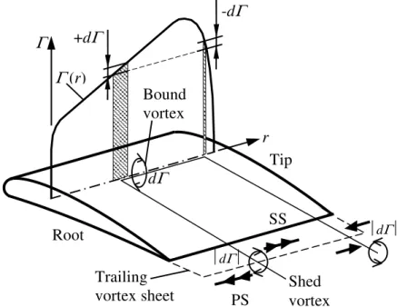
Beside the above-discussed advantages offered by CVD, the design difficulties and potential disadvantages related to spanwise changing blade circulation must be acknowledged. An unavoidable consequence of spanwise blade circulation gradient is that vortices are shed from the blade trailing edge [1]. Associated with the shed vortices, a characteristic 3D flow pattern fills the entire blade passage, manifesting itself in radially outward and inward flow on the suction side and on the pressure side, respectively. This “non-free vortex” nature of flow has been described in detail, e.g. in [70-71]. The stream sheet twisting associated with the 3D interblade flow makes the applicability of two-dimensional (2D) airfoil or cascade theory doubtful in preliminary blade
dc_242_11
design. CVD concepts based on 2D airfoil or cascade data are compelled to neglect the pitchwise variation of radial velocity [72], although such design simplification does not undermine the success of the design in certain cases [74].
1.4. Precedents
This thesis work aims at contributing to a more comprehensive understanding of aerodynamic effects described in the previous sections, as a continuation of axial flow fan R&D related in recent decades to the Department of Fluid Mechanics – termed herein Department –, Budapest University of Technology and Economics. The following section gives a brief literature overview of the most relevant historical precedents in Hungary from the viewpoint of the scope of the thesis, i.e. spanwise changing rotor blade circulation, and CVD.
Dating back to the middle of the last century, the spanwise change of total pressure rise was considered in the characteristic curve calculation already in the thesis work by Gruber [75]. The CVD concept dates back to the middle of the last century in the international literature, e.g. [76-78].
The starting point of systematic application of the CVD method in Hungary is dedicated to the activity by Somlyódy [59, 79-81]. In [59], referring to [80], a CVD method was proposed relying on a power function blade circulation distribution along the span. The 3D rotor flow related to non- free vortex operation was modelled by Nath in [82-83]. Bencze and Szlivka report in [84] on a CVD technique incorporating a spanwise blade circulation distribution expressed as the difference between two power functions. The applicability of the CVD methodology was tested experimentally in [85-86]. The design and operational experiences related to axial fans were summarised by Gruber and his departmental co-authors [87]. The gathered background knowledge has been expanded to mixed flow fans by Vajna [88]. In design, applications, R&D, and education related to turbomachinery, work represented by Czibere, Fáy, Főzy, Kovács, Kullmann, and Nyíri, as well as by their co-workers, is additionally acknowledged herein, e.g. [177, 192-195].
Based on the CVD methodology elaborated at the Department, several axial fan types were designed and a large number of fans were manufactured for domestic applications as well as for exportation. These fans covered a wide range of application areas, such as especially silent industrial and building service engineering fans; roof ventilation units; single-stage reversible subway ventilation fans; flue gas extractor units; two-stage, swirl-controlled boiler combustion air fans for power plants; fan units for industrial chilling technology (e.g. for deep-freezing tunnels);
counter-rotating fans; ventilating fans for mobile condensers; crop and forage drying equipments;
fans for chemical industry applications.
Adopting the technique of laser Doppler anemometry (LDA) to turbomachinery, the author contributed to the departmental R&D programme by investigating the 3D flow field developing in
dc_242_11
axial flow fans of CVD, within the framework of his Ph.D. project [89-91] supervised by Bencze.
Previous departmental R&D activity on axial fans of CVD has had an effect up to now in practical applications in Hungary, e.g. in agricultural engineering. In this field, publications have been elaborated at Szent István University [64, 92].
At the Department, the author and the team supervised by him gathered experience in design, measurement, R&D, and expert activity related to fan rotors of non-radial stacking and/or CVD.
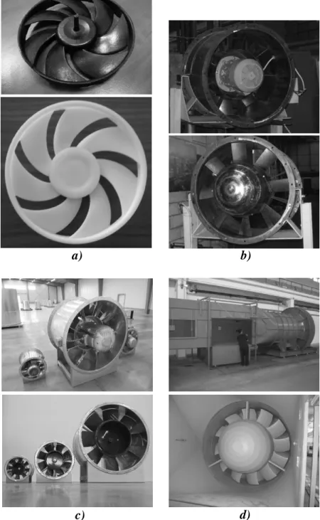
Figure 1.1 presents some examples on the fans designed by the author within a basic research project [94-95], designed under his supervision [96], and investigated by him and his team experimentally for industrial customers. The manufacturers/vendors of the latter fan group are non- disclosed herein for confidentiality reasons. However, representative photos for such fan types are available in [97-100]. Figure 1.2 shows realized axial fans of CVD designed by the author for industrial firms and end-users in Hungary [69, 99, 101-103].
1.5. Objectives of the thesis work
Non-radial blade stacking and CVD often characterise the axial flow blade rows simultaneously in practical applications (see Figs. 1.1 and 1.2 for illustration). Some examples are as follows: low-pressure cooling and industrial ventilating fans [18, 21, 37-38, 50, 74, 104], automotive cooling fans [6-7, 9-12, 15], high-pressure industrial fans [25-26], low-speed compressors [19, 43]. The interpretation of effects of non-radial stacking applied to CVD rotors is challenging. Due to the formerly outlined 3D nature of blade passage flow in rotors of CVD, the exploration and aerodynamic judgment of 3D effects due to sweep and skew is especially complicated in the case of CVD bladings.
The objectives of the thesis are to: i) extend the knowledge published in the literature on the aerodynamic effects due to blade sweep and skew applied to axial fans; ii) achieve a more comprehensive understanding of fluid mechanical impact of sweep and skew applied to axial fan bladings of CVD; iii) contribute to guidelines for the improvement of preliminary blade design methods, on the basis of the above. Accordingly, the design operating point is under discussion.
Off-design behaviour is out of the scope of the thesis.
The classical publications related to turbomachinery design, e.g. [57, 72, 87, 105-110], aim at providing theoretical and/or empirical relationships for approximate quantification of airfoil, blade cascade or rotor performance and losses, as an aid to preliminary rotor blade design disregarding non-radial stacking effects. For consideration of aerodynamic phenomena related to non-radial blade stacking, several publications propose quantitative empirical relationships in specific applications, e.g. [21, 28, 74], or provide approximate formulae with neglect of certain effects such as viscosity [2, 13] or wall proximity [104, 111-112]. The practical applicability of
dc_242_11
such approximations was proven in certain case studies, e.g. [104], and the technical merit of such approximate models must be acknowledged. However, it is beyond the expectations to elaborate generally applicable quantitative formulae taking the complex non-radial stacking effects exhaustively into account. Instead, the following work strategy can be tracked in the literature.
Qualitative trends related to non-radial blade stacking have been under exploration until recently, e.g. [17, 24, 26-27, 43, 45-46, 54-56, 113-115], with extensive use of experimentation as well as Computational Fluid Dynamics (CFD). Considering the qualitative experiences, various versions of non-radially stacked blading geometry can be individually designed. Afterwards, finding the most favourable blading version(s) is expected from CFD studies coupled with experiments, as e.g. in [21, 28-29, 38], using “cut-and-try” approaches [116], occasionally in an iterative manner. Besides such methodology, a recent trend is the application of CFD-based, algorithmized optimisation techniques [117]. In these methods, the blading versions under CFD surveillance do not originate from individual design (i.e. necessitating human contribution) but are tailored systematically by appropriate algorithms. Such algorithmized optimisation techniques incorporate non-radial stacking with the capacity to systematically adjust the stacking line shape [52-53, 118-123], as well as blade section geometry [50, 116, 124] and stagger. The strategies to harmonise the parametrized adjustment of various blading characteristics are aided by the formerly explored qualitative trends related to non-radial stacking.
The above underline the importance of qualitative knowledge on non-radial stacking effects.
Accordingly, a main objective of the present thesis is to establish novel qualitative – and, to a certain extent, quantitative – guidelines contributing to the design of axial flow blading of sweep or skew, with special regard to CVD. These guidelines can be incorporated in the preliminary design (first cut) of blade geometry, and support the elaboration of CFD-based design strategies as well.
The corresponding studies have been strongly supported by the departmental CFD experience related to fluid machinery [125-129].
Initiated by the aforementioned practical demands, the guideline of the work presented herein is, although not limited to, the exploration of combined effects due to CVD and FSW.
Accordingly, the thesis chapters have been organized to the following logical structure:
• Effects of CVD to the near-endwall – more specifically, near-tip – region, influenced by FSW (Chapter 2),
• Effects of CVD away from the endwalls, influenced by FSW (Chapter 3),
• Systematic incorporation of FSW in the preliminary CVD methodology, based on the conclusions drawn in the previous chapters (Chapter 4).
dc_242_11
Figure 1.1. Fan rotors designed and experimentally certified by the author in a basic R&D project [cases b), c)], designed under his supervision [case d)], and studied by him and his team within the framework of industrial projects [cases e), f), g)]. a) High-pressure ventilating fan of CVD with radially stacked blades [85, 93]. b) Redesign of case a) for modified spanwise blade circulation distribution [94]. c) Redesign of case a) incorporating FSW [95]. d) Sketch of a small-scale CVD industrial fan of high specific performance: Radially stacked (left) and slightly forward-skewed (right) versions [96]. e) CVD rotors of radially stacked and forward-skewed blades, applied in heat exchanger units [9, 97]. f) CVD industrial fan rotor of radial blade stacking and variable stagger [98-99]. g) Destratification jet fan of forward skewed blades [100].
a) b) c)
e)
g) d)
f)
dc_242_11
Figure 1.2. Examples for axial fans of CVD designed by the author for industrial firms and end- users in Hungary, with specification of blade tip diameters. a) Electric motor cooling fans with forward-skewed blades, ∅ 110 mm, ∅ 124 mm [69]. b) Fan of long throw, with radially stacked blades, ∅ 710 mm [99, 101]. c) Flue gas extractor fans with radially stacked blades, ∅ 400 mm, ∅ 630 mm, ∅ 1250 mm [102]. Wind tunnel fan with forward-skewed blades, ∅ 2000 mm [103].
a) b)
c) d)
dc_242_11
2. RADIAL FLUID MIGRATION AND NEAR-TIP BLOCKAGE 2.1. Introduction
It is known that the fluid in the boundary layer of axial flow fan and compressor rotor blades migrates radially outward and accumulates near the tip [19], especially on the suction side, e.g.
[130-132]. Based on e.g. [1, 48, 133], the present discussion focuses on the suction side of the blades, where the aerodynamic loss is expected to be more pronounced. The high-loss fluid stagnating near the tip contributes to increased local losses, and promotes "tip stalling" [134] at throttled conditions. It is also highlighted in [1] that the radial flows inside the blade profile boundary layer introduce spanwise gradients in blade circulation and losses, and increase the mixing loss. The undesired phenomenon of radial outward migration of high-loss fluid is generally interpreted as "outward centrifugation", as e.g. in [19, 70, 135, 154, 191], i.e. it is dedicated to the dominance of centrifugal force over the radial pressure gradient [1]. As a supplement to this simplified interpretation, it was aimed to elaborate and apply a model for comprehensive investigation of the factors influencing the radial outward migration of fluid, at the design flow rate.
Up-to-date CFD techniques are available for the reliable prediction of 3D turbomachinery flow. It appears to be beneficial to supplement these techniques with analytical models for exploring the underlying physics of 3D flow effects. Lifelike simplified models (e.g. as in [19, 136]) may contribute to the elaboration of guidelines for controlling the related flow phenomena by design means.
Radial fluid motion is especially significant in the case of rotors of CVD. The aim of the present chapter is to explore the common aspects of radial outward migration, the related endwall blockage, and CVD. For this purpose, analytical modelling, evaluation of detailed flow measurement data, and quantitative analysis of endwall blockage have been carried out on comparative bladings of case study.
Studies in this subject performed by the author were preliminarily documented in [4, 137- 138, 144, 146]. The author has summarized his new independent scientific results in [139].
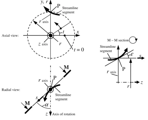
2.2. Analytical modelling of radial fluid migration 2.2.1. Obtainment of radial acceleration
Let us consider a 3D streamline segment (Figure 2.1) fitting to point P where the geometrical and physical circumstances are under investigation. The radial coordinate is r. The r coordinate axis, characterised by unit vector ur, fits to P, intersects the z-axis of rotation (axial coordinate axis), and is normal to it. The projection of the streamline onto the cylindrical surface of radius r makes an angle α with the axis of rotation. The projection of the streamline onto the plane,
dc_242_11
being tangential to the streamline and containing the r axis, makes an angle ε with the cylindrical surface of radius r. An [x, y, z] Cartesian coordinate system is introduced, for which z is the axis of rotation, the y-axis fits to the r axis, and ux×uy =uz. The streamline is described parametrically with use of the x(t), y(t), z(t) functions, for which the independent parameter t is the polar angle coordinate in the [r, t, z] cylindrical coordinate system.
Figure 2.1. Geometrical circumstances
Derivative vectors h'P and h''P are obtained for P. h'P is composed by the first derivatives and h''P is composed by the second derivatives of the x(t), y(t), z(t) functions with respect to t. See Appendix A for the details of h'P and h''P, and for the definition of the [r, n, s] coordinate system.
The centripetal acceleration of the fluid in the natural coordinate frame connected to point P can be expressed as follows. For explanation, see Appendix B.
(
P P)
P4 P
2
cp ' '' '
' h h h
h
a = w × × (2.1)
The y-wise component of acp in Eq. (2.1) is considered, being equal to the radial component of the centripetal acceleration (Fig. 2.1). It can be pointed out that
( )
[ ] [ ( ) ( ) ]
P2 2 P
P
P '' ' ' ' '' ' '' ' '' '
' h h x z y x x z z y
h × × y = + − + (2.2)
The derivatives are to be substituted from Appendix A into Eq. (2.2). Using derivatives and trigonometric transformations yields
(
2)
22 4 2
P 1 tan
' sin
+
= ε
α
h r (2.3)
M
Streamline segment
r axis
Axis of rotation
z P
M s α
x y, r
r t P r axis
z axis
Streamline segment
M – M section
r s
z ε r axis P
Streamline segment
t = 0
Axial view:
Radial view:
dc_242_11
Furthermore, w = ws / cos ε is considered on the basis of Figure A1.d) in Appendix A.
Substitution of Eqs. (2.2) and (2.3) into Eq. (2.1) reads, after several steps, the following expression:
[ ] [ ]
−
∂
= ∂
= a w s r
a y r s2 ε 2α
cp cp
sin (2.4)
In the case of ∂ε/∂s = 0, considering that wssinα = wu, [acp]y= – wu2/r. This corresponds to the classic view that, in the case of a cylindrical stream surface, the radial component of acceleration appears as the centripetal acceleration of fluid particles moving virtually at a tangential velocity wu
on a circle of radius r (conf. [1]).
The streamwise unit vector [tangential to the streamline, see Fig. A1.d) in Appendix A] in the natural coordinate frame connected to P is ue =h'p h'p . The streamwise acceleration of the fluid is
e
e u
e w w
a ∂
= ∂ (2.5)
The radial component of the streamwise acceleration is obtained as follows, on the basis of Eq. (2.5). It is considered that w = ws/cos ε. Furthermore, ∂w/∂e = (∂w/∂s)⋅(∂s/∂e), where ∂s/∂e = cosε [see Fig. A1.b) in Appendix A]. The y-wise component of ue, being equal to its radial component, is expressed using the derivatives in Appendix A, with the final result of [ue]r = sinε. The above read, after several steps
[ ] [ ]
∂ + ∂
∂
= ∂
= w s
s w w a
ae y e r s s tanε stan2ε ε (2.6)
The sum of Eqs. (2.4) and (2.6) reads the radial component of fluid acceleration, considering intermediately that (1+tan2ε)(∂ε/∂s) = ∂ (tanε)/∂s:
( )
w r s
w w w s
ar s2 ε s s ε s2 sin2α
tan tan −
∂ + ∂
∂
= ∂ (2.7)
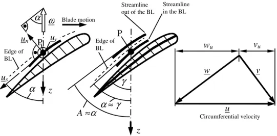
Following the view in [1], two regions are distinguished in the vicinity of the blade: the boundary layer influenced by viscous effects, and the inviscid core flow. Let us study two neighbouring streamlines, as illustrated in Figure 2.2: one streamline in the suction side boundary layer of the blade, fitting point P; and the other one out of the boundary layer (in the core flow) near the boundary layer edge. Let us consider the characteristics ar, ws, ε, and α in Eq. (2.7), and also the local static pressure p and absolute velocity v, as the features of the fluid on the streamline in the boundary layer, in point P. On the streamline out of the boundary layer, the following characteristics are introduced, in analogy to the above ones: a→@; w→W; v→V; ε→E; α→A;
p→P. With these characteristics, the radial acceleration of the fluid out of the boundary layer is the
![Figure IV.1 [4]. Representation of blade sweep, dihedral, and circumferential skew, on selected blade portions](https://thumb-eu.123doks.com/thumbv2/9dokorg/1278943.101877/15.892.134.866.60.830/figure-representation-blade-sweep-dihedral-circumferential-selected-portions.webp)
![Figure 1.1. Fan rotors designed and experimentally certified by the author in a basic R&D project [cases b), c)], designed under his supervision [case d)], and studied by him and his team within the framework of industrial projects [cases e), f](https://thumb-eu.123doks.com/thumbv2/9dokorg/1278943.101877/23.892.172.764.61.762/designed-experimentally-certified-designed-supervision-framework-industrial-projects.webp)