Citation:Daku, G.; Vad, J.
Preliminary Design Guidelines for Considering the Vibration and Noise of Low-Speed Axial Fans Due to Profile Vortex Shedding.Int. J.
Turbomach. Propuls. Power2022,7, 2.
https://doi.org/10.3390/ijtpp7010002 Received: 28 September 2021 Accepted: 4 January 2022 Published: 7 January 2022
Publisher’s Note:MDPI stays neutral with regard to jurisdictional claims in published maps and institutional affil- iations.
Copyright: © 2022 by the authors.
Licensee MDPI, Basel, Switzerland.
This article is an open access article distributed under the terms and conditions of the Creative Commons Attribution (CC BY-NC-ND) license (https://creativecommons.org/
licenses/by-nc-nd/4.0/).
Turbomachinery Propulsion and Power
International Journal of
Article
Preliminary Design Guidelines for Considering the Vibration and Noise of Low-Speed Axial Fans Due to Profile
Vortex Shedding †
Gábor Daku * and János Vad
Department of Fluid Mechanics, Faculty of Mechanical Engineering, Budapest University of Technology and Economics, Bertalan Lajos u. 4-6, H-1111 Budapest, Hungary; vad@ara.bme.hu
* Correspondence: daku@ara.bme.hu
† This paper is a revised version of our paper published in Proceedings of the European Turbomachinery Conference ETC14, Gdansk, Poland, 12–16 April 2021.
Abstract:This paper presents a critical overview on worst-case design scenarios for which low-speed axial flow fans may exhibit an increased risk of blade resonance due to profile vortex shedding. To set up a design example, a circular-arc-cambered plate of 8% relative curvature is investigated in twofold approaches of blade mechanics and aerodynamics. For these purposes, the frequency of the first bending mode of a plate of arbitrary circular camber is expressed by modeling the fan blade as a cantilever beam. Furthermore, an iterative blade design method is developed for checking the risky scenarios for which spanwise and spatially coherent shed vortices, stimulating pronounced vibration and noise, may occur. Coupling these two approaches, cases for vortex-induced blade resonance are set up. Opposing this basis, design guidelines are elaborated upon for avoiding such resonance.
Based on the approach presented herein, guidelines are also developed for moderating the annoyance due to the vortex shedding noise.
Keywords:axial flow fan; blade vibration; low tip speed; preliminary fan design; vortex shedding
1. Introduction
Vortex shedding (VS) from low-speed axial flow fan rotor blades has become of engineering relevance in the past decades. The VS phenomenon discussed in this paper—
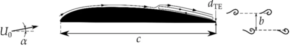
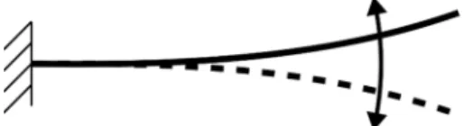
termed herein as profile vortex shedding (PVS), and illustrated in Figure1—is not to be confused with the trailing-edge-bluntness, VS, which takes place past the blunt trailing edge (TE) of the blade profile, acting as the aft portion of a bluff body [1]. In the aforementioned literature, PVS is referred to as a laminar-boundary-layer VS, because it can only occur if the boundary layer is initially laminar at least over one side of the blade profile. In this case, the initially laminar boundary layer, being separated near or after mid-chord position, reattaches in the vicinity of the TE—thus resulting in a separation bubble—and finally undergoes a laminar-to-turbulent transition. Moreover, the position and the size of the formed separation bubble plays a key role in tonal PVS noise emission. Recently, Yakhina at al. [2] published a detailed investigation about tonal TE noise radiated by low Reynolds number airfoils. They observed that a precondition for tonal noise emission is the formed separation bubble being sufficiently close to the TE. PVS may occur within a certain Reynolds number range. Based on the literature [3–5], a lower limit ofRec= 5×10⁴ is assumed herein, while the upper limit is determined by the critical Reynolds number of the natural laminar-to-turbulent transition. When PVS is discussed for low-speed fans, as in the present paper, incompressible flow is considered by implying a Mach number of≤0.3.
Int. J. Turbomach. Propuls. Power2022,7, 2. https://doi.org/10.3390/ijtpp7010002 https://www.mdpi.com/journal/ijtpp
Int. J. Turbomach. Propuls. PowerInt. J. Turbomach. Propuls. Power 2022, 7, x FOR PEER REVIEW 2022,7, 2 2 of 23 2 of 23
Figure 1. Profile vortex shedding (PVS).
Various models are available in the literature on the PVS phenomenon. In this paper, only the classic model by Tam [6] and Wright [7] is referred to, in order to provide a straightforward and comprehensive interpretation on the mechanism. According to this model, PVS is related to a self-excited feedback loop. Due to the unstable laminar bound- ary layer, Tollmien–Schlichting instability waves are generated; these waves travel down- stream toward the TE where sound scattering occurs, and acoustic waves are created. The acoustic waves propagate upstream to amplify the original instabilities. If appropriate phase conditions are fulfilled, the disturbances are amplified at some frequencies, thus closing the feedback loop. Later, a number of authors, e.g., Nash et al. [8], carried out a critical revision on the aforementioned feedback loop model. PVS may generate vibration on the blade. As the studies by Ausoni et al. [9] suggest, the mechanisms of periodic vortex shedding and periodic blade vibration may mutually be coupled at a blade eigenfre- quency, within a “lock-in” phenomenon.
In the case of low-speed axial flow fan blades, the difference between PVS and TE- bluntness VS in their physical mechanisms manifests itself in scaling techniques and the values of the Strouhal number being also different.
For blade profiles with thick or blunt trailing edges, the TE-bluntness vortex shed- ding [10] can be characterized by the Strouhal number based on the free-stream velocity U0 and the TE thickness dTE:
20 . 0 / 0 TE TE
TE = f d U ≅
St (1)
For PVS [11,12], which is associated with the boundary layer transition and feedback mechanism:
18 . 0 / 0
PVS
*= f b U ≅
St (2)
where f is the dominant frequency of the two types of VS, and b is the distance between the vortex rows. Yarusevych et al. [11] found that St* is universally valid for symmetrical, relatively thick NACA airfoils for certain ranges of the Reynolds number and angle of attack, suggesting the appellation of a “universal” Strouhal number St*, as specified in Equation (2). However, these airfoils are not widely used in axial fan application; there- fore, the present authors have extended the proposed St* definition as follows. Systematic wind-tunnel experiments were performed on blade section models typical for low-speed axial fans, using a single-component hot-wire probe. Based on the measured f and b val- ues, the authors also confirmed the validity of St* for asymmetrical profile geometries, such as 8% cambered plate and RAF-6E profiles, in a quasi-2D experimental analysis [13].
Thus, the available experimental database on PVS frequency [5] was extended.
From an engineering point of view, the practical aspects of PVS are remarkable in two ways: vibration and noise. On the one hand, PVS creates a periodically fluctuating force normal to the chord, increasing the risk of blade vibration. On the other hand, VS appears as the primary source of the aeroacoustics noise of low-speed axial flow fans [14–
16]. Hence, it is an important engineering objective to check and possibly to control the vibration and noise of low-speed axial fans due to the PVS that is already in the prelimi- nary design phase. It is worth noting that the signatures of blade vibration and PVS-re- lated noise may coincide in the frequency spectra. In [17], the vibrometer connected to the airfoil indicated a vortex-induced vibration, the dominant frequency of which coincided with that of the far-field tone.
Figure 1.Profile vortex shedding (PVS).
Various models are available in the literature on the PVS phenomenon. In this paper, only the classic model by Tam [6] and Wright [7] is referred to, in order to provide a straightforward and comprehensive interpretation on the mechanism. According to this model, PVS is related to a self-excited feedback loop. Due to the unstable laminar boundary layer, Tollmien–Schlichting instability waves are generated; these waves travel downstream toward the TE where sound scattering occurs, and acoustic waves are created. The acoustic waves propagate upstream to amplify the original instabilities. If appropriate phase conditions are fulfilled, the disturbances are amplified at some frequencies, thus closing the feedback loop. Later, a number of authors, e.g., Nash et al. [8], carried out a critical revision on the aforementioned feedback loop model. PVS may generate vibration on the blade.
As the studies by Ausoni et al. [9] suggest, the mechanisms of periodic vortex shedding and periodic blade vibration may mutually be coupled at a blade eigenfrequency, within a
“lock-in” phenomenon.
In the case of low-speed axial flow fan blades, the difference between PVS and TE- bluntness VS in their physical mechanisms manifests itself in scaling techniques and the values of the Strouhal number being also different.
For blade profiles with thick or blunt trailing edges, the TE-bluntness vortex shed- ding [10] can be characterized by the Strouhal number based on the free-stream velocityU0
and the TE thicknessdTE:
StTE= fTEdTE/U0∼=0.20 (1) For PVS [11,12], which is associated with the boundary layer transition and feedback mechanism:
St∗= fPVSb/U0∼=0.18 (2)
wheref is the dominant frequency of the two types of VS, andbis the distance between the vortex rows. Yarusevych et al. [11] found thatSt* is universally valid for symmetrical, relatively thick NACA airfoils for certain ranges of the Reynolds number and angle of attack, suggesting the appellation of a “universal” Strouhal numberSt*, as specified in Equation (2). However, these airfoils are not widely used in axial fan application; therefore, the present authors have extended the proposedSt* definition as follows. Systematic wind-tunnel experiments were performed on blade section models typical for low-speed axial fans, using a single-component hot-wire probe. Based on the measuredfandbvalues, the authors also confirmed the validity ofSt* for asymmetrical profile geometries, such as 8% cambered plate and RAF-6E profiles, in a quasi-2D experimental analysis [13]. Thus, the available experimental database on PVS frequency [5] was extended.
From an engineering point of view, the practical aspects of PVS are remarkable in two ways: vibration and noise. On the one hand, PVS creates a periodically fluctuating force normal to the chord, increasing the risk of blade vibration. On the other hand, VS appears as the primary source of the aeroacoustics noise of low-speed axial flow fans [14–16]. Hence, it is an important engineering objective to check and possibly to control the vibration and noise of low-speed axial fans due to the PVS that is already in the preliminary design phase. It is worth noting that the signatures of blade vibration and PVS-related noise may coincide in the frequency spectra. In [17], the vibrometer connected to the airfoil indicated a vortex-induced vibration, the dominant frequency of which coincided with that of the far-field tone.
Measurements on PVS in the literature are mostly related to isolated and steady airfoils [2,11–13,17,18]. Only a few studies dealt with PVS in the case of rotating blades of asymmetrical profiles being characteristic for realistic axial fans. Longhouse [19] detected
Int. J. Turbomach. Propuls. Power2022,7, 2 3 of 23
PVS noise on an axial fan of four cambered plate blades with a constant blade chord.
Nevertheless, except for a small segment (~10%) of the span of one blade in near-tip region, the PVS noise was suppressed by aft-chord serrations. Furthermore, the spanwise variation of free-stream velocity tended to broaden the noise signature of PVS, thus acting against a remarkable, well-detectable tonal PVS character. Grosche and Stiewitt [20] examined a four-bladed propeller-type axial fan rotor with a moderate sweep and twist. They observed PVS noise atα≈4◦angle of attack, viewed in the rotating frame of reference near the blade tip, for three different Reynolds numbers based on the chord length (Rec= 9×10⁴, 1.3×10⁵, 2.6×10⁵). All of the aforementioned observations—both the isolated blade profile and rotor consideration—suggest that the following blade features tend to increase the inclination for the occurrence of well-detectable tonal PVS: high aspect ratio (AR), low solidity, moderate twist, and constant blade chord. These parameters are typical for propeller-type fans [21]. Such propeller-type fans, where low-solidity is characteristic over a significant portion of the span, have been designed, for instance, by [22,23].
In order to moderate the harmful noise and vibration effects due to PVS, pessimistic design scenarios have systematically been discovered for which such harmful effects are pronounced. Furthermore, these design characteristics were coupled with rotor dynamics consideration. Based on this coupling, an exemplary unfavorable design case was set up in terms of both operational and geometrical characteristics, for which PVS demonstrates an increased risk of blade resonance. Taking the rotor of such an unfavorable design case—termed hereafter the PVS-affected rotor—as reference, approximate semi-empirical design guidelines can already be elaborated in the preliminary design phase for checking and possibly avoiding PVS-induced resonance. The design guidelines for noise reduction, reported in [13], have also been further developed toward a more detailed model, as illustrated in this paper.
2. Blade Vibration: An Overview
Turbomachinery blade profiles are suggested to be modeled in preliminary analysis as simple cantilever beams [24–30], which means that all degrees of freedom of the blades at the blade root, i.e., where connected to the hub, are constrained. The pure bending—
or, in other words, transversal or flexural—vibrations of a prismatic beam with uniform cross-section according to time (τ) and the coordinate along the longitudinal direction of the beam (z) are described by the partial differential equation below, which is derived from the Euler-Bernoulli’s beam theory [26,31]:
EI∂4g(z,τ)
∂x4 +ρbA∂2g(z,τ)
∂τ2 =0 (3)
where g(z,τ) is the lateral displacement along the axis perpendicular to the blade chord;
Eis the Young modulus; Iis the second moment of area with respect to the axis being parallel to the chord and fitting to the center of gravity (CG) of the blade section;Ais the cross-sectional area of the blade profile; andρb is the density of the blade material.
The method of variable separation can be used to produce the free vibration solution. By utilizing the proper initial and boundary conditions, thei-th eigenfrequency (see later) and normal mode shape [31] can be expressed as follows:
Fi(z) = (cosβiz−coshβiz)−(cosβil+coshβil)
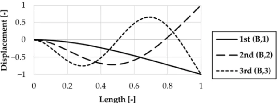
(sinβil−sinhβil)(sinβiz−sinhβiz) (4) whereiis the order-number, i.e., 1, 2, 3 etc.; F(z) is the characteristic function or the normal mode of the beam;lis the radial extension of blade from hub to tip, i.e., the blade span, and βil≈(2i−1)π/2. For illustrative examples, Figure2qualitatively presents the shapes for some bending modes, generated on the basis of Equation (4). The vertical axis represents the normal mode (i.e., dimensionless displacement) and the horizontal axis shows the dimensionless length of the beam.
Int. J. Turbomach. Propuls. Power2022,7, 2 4 of 23
Int. J. Turbomach. Propuls. Power 2022, 7, x FOR PEER REVIEW 4 of 23
for some bending modes, generated on the basis of Equation (4). The vertical axis repre- sents the normal mode (i.e., dimensionless displacement) and the horizontal axis shows the dimensionless length of the beam.
Figure 2. Normal bending modes of the beam.
The pure torsion of the cantilever beam is governed by the following differential Equation [32]:
( )
,( )
, 02 2 p 2 b
2
t =
∂ + ∂
∂
∂
τ τ ρ ζ
τ
ζ I z
x
GI z (5)
where ζ(z, τ) is the rotation angle around the longitudinal direction of the beam; G is the shear modulus; It is the torsional stiffness or torsional constant; and Ip is the polar moment of area of the blade section.
It is important to note that in practice, mixing of modes can occur, and accordingly, various researchers have executed studies on experimental and theoretical evaluations of flexural-torsional vibration analysis, taking into account the coupling of flexural and tor- sional modes, e.g., [24,27,28,31,33,34]. The present authors have only dealt with pure bending and torsional vibration modes, keeping in mind the simplest possible analytical description mode.
In the literature, basic concepts are available for the analytical treatment of the vibra- tion of beams/blades affected by centrifugal force field due to their rotation. Such concepts regard both untwisted [31] and twisted [24,28,29] geometries. As discussed in [25], the centrifugal force originating from the rotation of the blades has a stiffness-increasing ef- fect, i.e., it tends to moderate the inclination of the blade to vibrate. At the present state of research, the authors neglect the mechanical effect of the centrifugal field, for the follow- ing reasons: (a) The centrifugal field tends to be of moderate significance in the low-speed fan blades discussed herein; and (b) the intention is to make a pessimistic—i.e., safety- increasing—preliminary design approach via neglecting the stiffness-increasing trend due to the centrifugal field. Blade twist tends to reduce the bending eigenfrequencies, as FEM computations (not presented herein) demonstrate. Therefore, for twisted blades, the critical frequencies of excitation tend to be shifted toward lower values. At the present state of research, the authors neglect the mechanical effect of blade twist. The reasonability of such neglect is commented on later on. The concerted review of the effects of centrifugal force field and blade twisting, or taking into account the mixing of the pure vibration modes, is planned to be the subject of future research.
Even mechanical or fluid mechanical excitations can unavoidably induce the vibra- tion of the axial flow fan blade to a certain extent, as well as being a source of vibration in the structure on which it is installed. Such excitation effect may derive from the interaction of the fan blades with the wake developing behind the elements placed upstream of the rotor e.g., supporting struts, inlet guide vanes, or even from the discussed PVS phenom- enon. For instance, corresponding to the pressure rise, a steady mean lift force acts on the blade. However, the lift force also has a varying component e.g., the fluctuating force due
Figure 2.Normal bending modes of the beam.
The pure torsion of the cantilever beam is governed by the following differential Equation [32]:
GIt
∂2ζ(z,τ)
∂x2 +ρbIp
∂2ζ(z,τ)
∂τ2 =0 (5)
whereζ(z,τ) is the rotation angle around the longitudinal direction of the beam;Gis the shear modulus;Itis the torsional stiffness or torsional constant; andIpis the polar moment of area of the blade section.
It is important to note that in practice, mixing of modes can occur, and accordingly, various researchers have executed studies on experimental and theoretical evaluations of flexural-torsional vibration analysis, taking into account the coupling of flexural and torsional modes, e.g., [24,27,28,31,33,34]. The present authors have only dealt with pure bending and torsional vibration modes, keeping in mind the simplest possible analytical description mode.
In the literature, basic concepts are available for the analytical treatment of the vibra- tion of beams/blades affected by centrifugal force field due to their rotation. Such concepts regard both untwisted [31] and twisted [24,28,29] geometries. As discussed in [25], the centrifugal force originating from the rotation of the blades has a stiffness-increasing effect, i.e., it tends to moderate the inclination of the blade to vibrate. At the present state of research, the authors neglect the mechanical effect of the centrifugal field, for the following reasons: (a) The centrifugal field tends to be of moderate significance in the low-speed fan blades discussed herein; and (b) the intention is to make a pessimistic—i.e., safety- increasing—preliminary design approach via neglecting the stiffness-increasing trend due to the centrifugal field. Blade twist tends to reduce the bending eigenfrequencies, as FEM computations (not presented herein) demonstrate. Therefore, for twisted blades, the critical frequencies of excitation tend to be shifted toward lower values. At the present state of research, the authors neglect the mechanical effect of blade twist. The reasonability of such neglect is commented on later on. The concerted review of the effects of centrifugal force field and blade twisting, or taking into account the mixing of the pure vibration modes, is planned to be the subject of future research.
Even mechanical or fluid mechanical excitations can unavoidably induce the vibration of the axial flow fan blade to a certain extent, as well as being a source of vibration in the structure on which it is installed. Such excitation effect may derive from the interaction of the fan blades with the wake developing behind the elements placed upstream of the rotor e.g., supporting struts, inlet guide vanes, or even from the discussed PVS phenomenon.
For instance, corresponding to the pressure rise, a steady mean lift force acts on the blade.
However, the lift force also has a varying component e.g., the fluctuating force due to PVS.
As detailed by [25,35], both forces produce a bending moment, resulting in vibration. If the dominant frequency of PVS coincides with an eigenfrequency of the blade, resonance may occur, and the intensity of the vibration can only be limited if the mechanical structure is stiff enough or damped sufficiently. Therefore, it is to be treated with special care in the case of fan blades made of cambered sheet metal plates because their eigenfrequency—due to the moderate inertia of the cross-section and the resulting lower stiffness—is lower compared to that of the profiled blades [25].
Int. J. Turbomach. Propuls. Power2022,7, 2 5 of 23
Even though fans commonly operate with mechanical stresses far below the capacity of their material—and thus the vibration of the fan blade due to resonance does not lead to the fracture of the mechanical structure—, in the presence of the corresponding stresses, which reach a maximum near the blade root, there can be a risk of fatigue fracture. These stresses combine with the centrifugal ones; therefore, a mixed type, alternating stress condition appears, which must be considered in the design of the fan.
Furthermore, the rotor may become imbalanced due to the deformation patterns associated with each resonance frequency of the blade, forcing the shaft to bend, escalating the initial imbalance and bending. If the excitation is sufficiently intense, resulting in a vibration of large amplitude, one of the fan blades can rub into the duct walls leading to rotor imbalance or the breaking down of the blades.
2.1. Analytical Treatment 2.1.1. Bending Modes
In order to provide a straightforward and comprehensive approach in preliminary design, avoiding any need for numerical computation at the present phase of research and as a solutions of Equation (3), the following analytically expressed eigenfrequencies are considered for the bending modes of an arbitrary prismatic rod, as specified in the literature [26]:
fB,i= KB,i l2
s E I
Aρb (6)
Namely, the simple analytical formula above can easily be extended to higher-order bending modes by substituting the appropriateKB,iconstant into Equation (6). The values ofKB,i for the first three bending modes areKB,1 = 0.560,KB,2 = 3.506 andKB,3 = 9.819, respectively.
2.1.2. Torsional Modes
By solving the expression in Equation (5), the eigenfrequency for torsional modes can be obtained using the analytical formula e.g., in [26], as follows:
fT,i = i−0.5 2l
sG It
ρb Ip (7)
In Equation (7) every variable can be determined—exceptIt—by utilizing the material and geometrical parameters of the blade. To calculate theIttorsional constant for a flat plate, the following relation is given in [26]:
It=Ktct3 (8)
wherecis the chord length (width of the plate);tis the thickness (height of the plate); and Ktis a mechanical constant which can be obtained from Figure 4.2 of [26] or calculated applying the formula—being in accordance with the former literature—e.g., [36]. However, the aforementioned alternatives for determining the torsion constant are related not to a cambered but to a flat plate, inhibiting their direct application in our case study. To overcome this problem, based on [36–38], the torsional constant of a thin-walled open tube cross-section of uniform thickness can be expressed as:
It= 1
3Ut3 (9)
whereUis the length of the midwall perimeter, shown dashed later in Figure 5.
Int. J. Turbomach. Propuls. Power2022,7, 2 6 of 23
2.2. Finite Element Method (FEM)
The FEM is a useful and generally accepted tool for solving engineering problems numerically, such as the modal analysis of rotor blades [39–41]. The desired mechanical characteristics can be computed by dividing an arbitrary mechanical structure into simple geometric shapes and defining the material properties and governing connections among these elements. In this study, the frequency analysis of a low speed axial fan blade is carried out using a commercial FEM software program ANSYS Mechanical APDL 2019 R3.
2.2.1. Geometry, Materials, and Elements
In the present paper, the hub is assumed to be rigid in comparison to the fan blade, thus all degrees of freedom of the blades at the hub, i.e., at the blade root, are constrained.
Therefore, only one segment of the axial flow fan composed of a single blade without a hub part was examined. In accordance with the later investigated PVS-affected rotor blade profile of the circular-arc-cambered plate of 8% relative curvature and the dimensional and dimensionless values of Tables 3 and 5, the necessary geometrical characteristics for 3D modeling are summarized in Table1. The reason for choosing this blade profile geometry will be explained in detail later in Section3.2. For the FEM case study, the fan blade is made of structural steel with a density of 7850 kg/m3, a Young’s modulus of 200 GPa, and a Poisson’s ratio (νP) of 0.3.
Table 1.Blade geometrical and material parameters for the FEM case study.
l c t h ρb E νP
264 mm 120 mm 2.40 mm 9.60 mm 7850 kg/m3 200 GPa 0.30
According to the literature [30,39], SHELL 181 element is suitable for analyzing thin to moderately-thick shell structures related to turbomachinery blades, such as wind turbine and axial flow fan blades. Hence, this type of element is applied to model the fan blade with 124 nodes in the axial direction and 256 nodes in the radial direction. Basically, SHELL 181 is a four-node element with six degrees of freedom at each node: translations in thex,y, andzdirections and rotations about thex,y, andz-axes. However, it should be mentioned that the same solution could be obtained by using the 20-node Hex20 (SOLID 186) element of Ansys Workbench 2019 R3.
2.2.2. Mesh Convergence
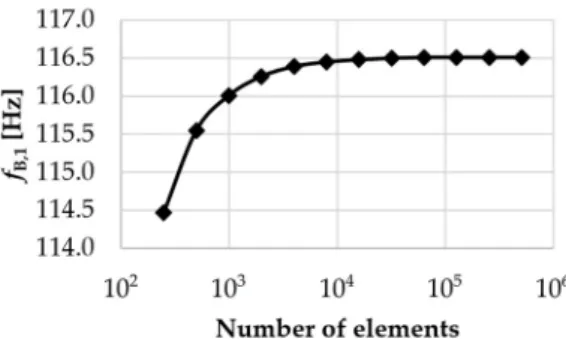
A mesh convergence study was performed to assure the optimum mesh number in terms of computational accuracy. The first three bending (B) and torsional (T) eigenfrequen- cies of the fan blade are computed in several mesh sizes (the element number varies from 258 to 507,904). By increasing the number of elements, the first bending eigenfrequency increases slightly and then becomes nearly constant. For higher-order bending and the torsional mode, similar effects can be observed. As shown in Figure3, 31,744 elements are appropriate to get a sufficiently accurate solution. Nevertheless, it should be mentioned that even a model with a lower number of elements is sufficient for the third-octave band prediction of the first bending eigenfrequency (see AppendixA).
Int. J. Turbomach. Propuls. Power2022,7, 2 7 of 23
Int. J. Turbomach. Propuls. Power 2022, 7, x FOR PEER REVIEW 7 of 23
Figure 3. Mesh convergence study.
2.3. Comparison of the Results
In Table 2, the first three analytical bending (B) and torsion (T) eigenfrequencies were calculated based on Equations (5), (7) and (8), and compared to the eigenfrequency ob- tained by means of FEM. The first column indicates the vibration mode case under dis- cussion. In the second and the fourth columns, FEM and the analytical eigenfrequencies are summarized, respectively. In the third and the fifth columns, the appropriate band number of the third-octave band resolution is listed in accordance with Appendix A. The
“Discrepancy” column contains the relative discrepancy of fanalytical in comparison to fFEM. Table 2. Geometrical and material parameters of the blade.
Mode fFEM [Hz]
1/3 Octave Band No.
fanalytical
[Hz]
1/3 Octave Band No.
Discrepancy [%]
B,1 116.5 11 116.1 11 0.3
B,2 595.2 18 727.6 19 18.2
B,3 1146.7 21 2037.8 23 43.7
T,1 140.1 11 117.4 11 19.4
T,2 472.8 17 352.1 15 34.3
T,3 949.6 20 586.9 18 61.8
From Table 2, it can be observed that the analytical treatment for the first bending (B,1) eigenfrequency is in good agreement with the FEM result. Nevertheless, for the higher-order bending and the torsional modes, the relative discrepancy between analyti- cal and FEM results becomes greater and tends to increase with the increasing of the order of the modes. A possible explanation for this is the partial violation of the briefly presented Euler–Bernoulli thin beam theory. Hence, the AR of the beam is equal to 2.2; namely, the beam is not considered to be slender (AR > 10).
Although there have been alternative methodologies to obtain a more accurate ana- lytical prediction for short beams (AR < 10), e.g., Timoshenko’s beam theory [31], the pre- sent paper focuses on Euler–Bernoulli’s beam theory, due to the following reasons. (a) On the one hand, the authors aim to create a closed analytical formula with the most straight- forward possible analytical description in mind. (b) On the other hand, as shown in [31,42], the relative discrepancy between the analytical first bending eigenfrequencies, cal- culated based on the two different theories, is less than 5–10%, which, fitting for point (a), is considered to be an acceptable approximation. Based on this and the highlighted role of the first bending mode detailed in Section 3.1, the confirmation of the analytical model by FEM is of primary significance for the first bending mode only and is of secondary importance for the other modes.
Despite the simplification assumption discussed at the beginning of the chapter (un- twisted and non-rotating fan blade), supplementary FEM case studies were carried out for the twisted and rotating blade as well. The FEM results demonstrated that both the blade twisting and the presence of a centrifugal force field have a bending eigenfrequency- Figure 3.Mesh convergence study.
2.3. Comparison of the Results
In Table 2, the first three analytical bending (B) and torsion (T) eigenfrequencies were calculated based on Equations (5), (7) and (8), and compared to the eigenfrequency obtained by means of FEM. The first column indicates the vibration mode case under discussion. In the second and the fourth columns, FEM and the analytical eigenfrequencies are summarized, respectively. In the third and the fifth columns, the appropriate band number of the third-octave band resolution is listed in accordance with AppendixA. The
“Discrepancy” column contains the relative discrepancy offanalyticalin comparison tofFEM. Table 2.Geometrical and material parameters of the blade.
Mode fFEM
[Hz]
1/3 Octave Band No.
fanalytical [Hz]
1/3 Octave Band No.
Discrepancy [%]
B,1 116.5 11 116.1 11 0.3
B,2 595.2 18 727.6 19 18.2
B,3 1146.7 21 2037.8 23 43.7
T,1 140.1 11 117.4 11 19.4
T,2 472.8 17 352.1 15 34.3
T,3 949.6 20 586.9 18 61.8
From Table2, it can be observed that the analytical treatment for the first bending (B,1) eigenfrequency is in good agreement with the FEM result. Nevertheless, for the higher-order bending and the torsional modes, the relative discrepancy between analytical and FEM results becomes greater and tends to increase with the increasing of the order of the modes. A possible explanation for this is the partial violation of the briefly presented Euler–Bernoulli thin beam theory. Hence, theARof the beam is equal to 2.2; namely, the beam is not considered to be slender (AR> 10).
Although there have been alternative methodologies to obtain a more accurate an- alytical prediction for short beams (AR< 10), e.g., Timoshenko’s beam theory [31], the present paper focuses on Euler–Bernoulli’s beam theory, due to the following reasons.
(a) On the one hand, the authors aim to create a closed analytical formula with the most straightforward possible analytical description in mind. (b) On the other hand, as shown in [31,42], the relative discrepancy between the analytical first bending eigenfrequencies, calculated based on the two different theories, is less than 5–10%, which, fitting for point (a), is considered to be an acceptable approximation. Based on this and the highlighted role of the first bending mode detailed in Section3.1, the confirmation of the analytical model by FEM is of primary significance for the first bending mode only and is of secondary importance for the other modes.
Despite the simplification assumption discussed at the beginning of the chapter (un- twisted and non-rotating fan blade), supplementary FEM case studies were carried out for the twisted and rotating blade as well. The FEM results demonstrated that both the blade twisting and the presence of a centrifugal force field have a bending eigenfrequency- reducing effect, providing an upper estimation for the first bending eigenfrequency of the blade. As the later calculation example illustrates, even in the case of the untwisted and
Int. J. Turbomach. Propuls. Power2022,7, 2 8 of 23
stationary fan blade, only impractically low tip speeds would result in the coincidence of the first bending eigenfrequency and PVS frequency. Therefore, the simplified fan blade model applied by the present authors can be considered as a pessimistic design scenario.
3. Blade Mechanics: An Exemplary Case Study 3.1. The Importance of the First-Order Bending Mode
The risk in fan operation due to blade vibration is simultaneously viewed in the present paper from the following two perspectives, which are related to each other. (a) The risk of instantaneous reduction of the gap between the blade tip and the casing. From the perspective of the tip gap reduction, the vibration modes exhibiting monotonously increasing deformation amplitude along the blade height are considered the riskiest. These are the first bending and first torsional modes. (b) The risk of instantaneous rotor imbalance.
This occurs in cases when the weight point of the entire blade is displaced in the transversal direction from its original position, fitting on the (approximately) radial blade stacking line, for which the rotor has originally been balanced. From the perspective of rotor imbalance, none of the torsional modes are considered to be risky, as they tend to leave the weight point of the entire blade (approximately) in its original position. In addition, according to their wavy vibration pattern, higher-order bending modes are considered to exhibit only a moderate transversal displacement of the blade weight point.
Therefore, among the various vibrational modes caused by PVS excitation, the first bending mode is judged to be the most critical, and the higher-order bending modes and torsional modes are considered of secondary significance. Consequently, out of the an- alytical solutions in Equation (5), the “first-order bending mode” is taken herein as an illustrative example of the analytical treatment elaborated upon by the authors. Neverthe- less, the reasonability of this choice is justified and supported by the subsequent examples, as follows.
The impact of PVS on both noise and vibration is presumed by the present authors to be pronounced when extensive and coherent vortices are shed with uniform frequency along a dominant portion of the blade span. In this case, PVS is assumed to exhibit pressure fluctuations over the blade suction and pressure surfaces, causing chord-normal forces.
Assuming spanwise and spatially coherent shed vortices, the resultant fluctuating forces are in phase over the entire span. Furthermore, PVS and the associated forces may occur farther upstream of the TE (cf. [12]). Such a PVS-induced excitation likely triggers the first-order bending mode.
An upstream stator, e.g., the nearly radially aligned supporting struts located upstream of the rotor, is able to cause wake-blade—also known as “rotor-stator”—interaction, in which the upstream wakes of the stator are swept downstream into the axial flow fan blade- row. The wakes are parallel with the relative velocity (w), thus the interaction manifests itself as a nearly simultaneous, spatially coherent aerodynamic excitation along the entire blade span. Hence, the fan blades are acted by chord-normal fluctuating force, resulting in a spatially coherent bending moment rather than torsional.
In addition, in [25] as a general approach, the frequency of the first bending mode of the blades is to be kept far away from the frequencies of excitation. As it was just mentioned, elements located upstream of the rotor—supporting struts and inlet guide vanes—cause rotor–stator interaction as aerodynamic excitation to the rotor blades, occur- ring at a frequency of rotational frequency multiplied by the number of upstream elements.
On the other hand, such excitation effects correspond to rotor imbalance (“shaker effect”) appearing as mechanical excitation at the rotational frequency of the fan.
Moreover, as illustrated in [5], the fluctuation of chord-normal force due to PVS may lead to a variance of the lift coefficient in the order of a magnitude of±10 percent of the temporal mean value. As demonstrated in [35], the varying component of lift force causes a bending moment on the blade. When extensive and coherent vortices are shed with uniform frequency along a dominant portion of the blade span, they represent spatially coherent elemental aerodynamic excitation forces, being in phase over the elemental blade
Int. J. Turbomach. Propuls. Power2022,7, 2 9 of 23
sections, and thus, integrated into a pronounced overall bending moment. The phase identity of the elemental excitation forces along the blade span matches with the phase identity of blade deformation in the first bending mode of the blade, if the frequency of PVS matches with the eigenfrequency related to the first bending mode.
3.2. Eigenfrequency
In order to build up a straightforward model for the interaction of the blade and the fluctuating aerodynamic force due to PVS, some simplifications must be introduced. First of all, a circular-arc-cambered plate of 8% relative curvature is chosen as a blade profile for several reasons:
(a) At moderate Reynolds numbers and angles of attack (α), the cambered plate produces reasonably highCL, that is comparable with an airfoil profile, i.e., RAF-6E [43], thus enabling the design of blades of relatively high specific performance, i.e., utilizing the loading capability of the blade sections.
(b) At 8% relative curvature, the lift-to-drag (LDR) is near the maximum among the cambered plates of various relative camber, thus enabling the design for reasonably high efficiency [44].
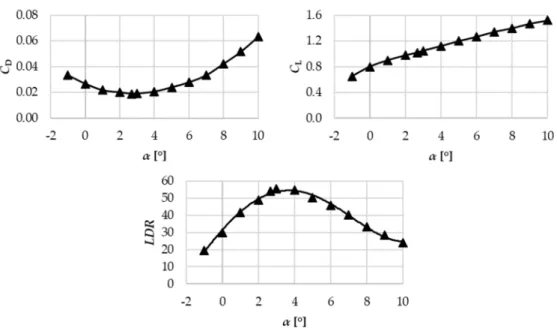
(c) In accordance with the aforementioned practical aspects, it is a cambered plate of 8% relative camber for which hot-wire measurement data are made available by the present authors on PVS at different free-stream velocities and angles of attack [13]. As per the illustration, Figure4showsCL,CD, andLDRvalues as a function of the angle of attack for the 8% cambered plate.
Int. J. Turbomach. Propuls. Power 2022, 7, x FOR PEER REVIEW 9 of 23
a bending moment on the blade. When extensive and coherent vortices are shed with uni- form frequency along a dominant portion of the blade span, they represent spatially co- herent elemental aerodynamic excitation forces, being in phase over the elemental blade sections, and thus, integrated into a pronounced overall bending moment. The phase identity of the elemental excitation forces along the blade span matches with the phase identity of blade deformation in the first bending mode of the blade, if the frequency of PVS matches with the eigenfrequency related to the first bending mode.
3.2. Eigenfrequency
In order to build up a straightforward model for the interaction of the blade and the fluctuating aerodynamic force due to PVS, some simplifications must be introduced. First of all, a circular-arc-cambered plate of 8% relative curvature is chosen as a blade profile for several reasons:
(a) At moderate Reynolds numbers and angles of attack (α), the cambered plate pro- duces reasonably high CL, that is comparable with an airfoil profile, i.e., RAF-6E [43], thus enabling the design of blades of relatively high specific performance, i.e., utiliz- ing the loading capability of the blade sections.
(b) At 8% relative curvature, the lift-to-drag (LDR) is near the maximum among the cam- bered plates of various relative camber, thus enabling the design for reasonably high efficiency [44].
(c) In accordance with the aforementioned practical aspects, it is a cambered plate of 8%
relative camber for which hot-wire measurement data are made available by the pre- sent authors on PVS at different free-stream velocities and angles of attack [13]. As per the illustration, Figure 4 shows CL, CD, and LDR values as a function of the angle of attack for the 8% cambered plate.
Figure 4. Lift and drag coefficients and lift-to-drag ratios as a function of angle of attack for 8%
cambered plate at Rec = 3 × 10⁵ measured by Wallis [44].
Secondly, the fan blade is presumed to consist of geometrically identical blade sec- tions along the full span. This means that the blade chord c, plate thickness t, and height of the camber line h are constants (Figure 5). The measurement data presented by [44] and shown in Figure 4, are related to a relative thickness (t/c) of 2%. This value is representa- tive in fan manufacturing; therefore, t/c is fixed at 2% for the present investigations.
Figure 4. Lift and drag coefficients and lift-to-drag ratios as a function of angle of attack for 8%
cambered plate atRec= 3×10⁵measured by Wallis [44].
Secondly, the fan blade is presumed to consist of geometrically identical blade sections along the full span. This means that the blade chordc, plate thicknesst, and height of the camber linehare constants (Figure5). The measurement data presented by [44] and shown in Figure4, are related to a relative thickness (t/c) of 2%. This value is representative in fan manufacturing; therefore,t/cis fixed at 2% for the present investigations.
Int. J. Turbomach. Propuls. PowerInt. J. Turbomach. Propuls. Power 2022, 7, x FOR PEER REVIEW 2022,7, 2 10 of 23 10 of 23
Figure 5. Circular-arc-cambered plate (8% relative camber).
Finally, as discussed earlier, it is assumed that all degrees of freedom of the blades at the hub, i.e., at the blade root, are constrained. This is a reasonable approximation; e.g., if sheet metal blades connect to the hub with a welded joint, or, in the case of polymer ma- terial, if the entirety of the hub and blading assembly is injection-molded as a single prod- uct. The simplifications above enable us to model the blade as a cantilever beam (or clamped beam) subjected to free vibration. In accordance with Section 3.1, the lowest ei- genfrequency, related to the first-order bending mode, can be calculated as follows:
b B,1 2
56 . 0
ρ E A I
f = l (10)
The last term on the right-hand side of Equation (10), as the square root of the specific modulus E/ρb, is termed herein the wave propagation speed, and denoted as ab. This is actually the acoustic wave propagation speed in a long one-dimensional fictitious beam made of the blade material. The resultant swinging pattern is shown in Figure 6.
Figure 6. Cantilever beam subjected to free vibration (perpendicular to the blade chord).
3.3. Second Moment of Area
The purpose of the present section is to demonstrate how the I/A term can be related to the basic geometrical characteristics of the circular-arc-cambered plate blade (c, h/c, t/c), creating a direct relationship between the first eigenfrequency and the geometrical param- eters of the blade. However, no closed analytical relationship exists in the literature for such purpose. Therefore, an alternative method must be found to express the second term of the right-hand side of Equation (10) with the use of blade geometrical parameters, such as c, h, and t. As a first step, the second moment of area of a cambered plate and a flat plate with same geometrical parameter (t, c) were compared to each other.
The quotient of the second moment of area and the cross-section, in case of a flat plate is:
( ) I Aflat = ( ct
3/ 12 ) ( ct ) = t
2 12
(11)
For a cambered plate it is:
( ) I A
cambered= K
1( ) I A
flat, where K
1= K
1(t / c, h / c)
(12) Icambered was obtained for the cambered plate-section using an analytical integration process known from basic solid-state mechanics [45]. As background information for the reader, the values of K1 are presented in Figure 7 for representative relative thickness and relative camber (h/c) values. For the fitted curves in Figure 7, K1 was calculated for fixed t/c values for uniform steps of 0.01 h/c over the entire h/c range. In the blade design pre- sented later, K1 (t/c = 0.02; h/c = 0.08) = 18.07 was used, in accordance with the previously selected blade geometrical parameters.Figure 5.Circular-arc-cambered plate (8% relative camber).
Finally, as discussed earlier, it is assumed that all degrees of freedom of the blades at the hub, i.e., at the blade root, are constrained. This is a reasonable approximation; e.g., if sheet metal blades connect to the hub with a welded joint, or, in the case of polymer material, if the entirety of the hub and blading assembly is injection-molded as a single product. The simplifications above enable us to model the blade as a cantilever beam (or clamped beam) subjected to free vibration. In accordance with Section3.1, the lowest eigenfrequency, related to the first-order bending mode, can be calculated as follows:
fB,1 = 0.56 l2
rI A
sE
ρb (10)
The last term on the right-hand side of Equation (10), as the square root of the specific modulusE/ρb, is termed herein the wave propagation speed, and denoted asab. This is actually the acoustic wave propagation speed in a long one-dimensional fictitious beam made of the blade material. The resultant swinging pattern is shown in Figure6.
Int. J. Turbomach. Propuls. Power 2022, 7, x FOR PEER REVIEW 10 of 23
Figure 5. Circular-arc-cambered plate (8% relative camber).
Finally, as discussed earlier, it is assumed that all degrees of freedom of the blades at the hub, i.e., at the blade root, are constrained. This is a reasonable approximation; e.g., if sheet metal blades connect to the hub with a welded joint, or, in the case of polymer ma- terial, if the entirety of the hub and blading assembly is injection-molded as a single prod- uct. The simplifications above enable us to model the blade as a cantilever beam (or clamped beam) subjected to free vibration. In accordance with Section 3.1, the lowest ei- genfrequency, related to the first-order bending mode, can be calculated as follows:
b B,1 2
56 . 0
ρ E A I
f = l (10)
The last term on the right-hand side of Equation (10), as the square root of the specific modulus E/ρb, is termed herein the wave propagation speed, and denoted as ab. This is actually the acoustic wave propagation speed in a long one-dimensional fictitious beam made of the blade material. The resultant swinging pattern is shown in Figure 6.
Figure 6. Cantilever beam subjected to free vibration (perpendicular to the blade chord).
3.3. Second Moment of Area
The purpose of the present section is to demonstrate how the I/A term can be related to the basic geometrical characteristics of the circular-arc-cambered plate blade (c, h/c, t/c), creating a direct relationship between the first eigenfrequency and the geometrical param- eters of the blade. However, no closed analytical relationship exists in the literature for such purpose. Therefore, an alternative method must be found to express the second term of the right-hand side of Equation (10) with the use of blade geometrical parameters, such as c, h, and t. As a first step, the second moment of area of a cambered plate and a flat plate with same geometrical parameter (t, c) were compared to each other.
The quotient of the second moment of area and the cross-section, in case of a flat plate is:
( ) I Aflat = ( ct
3/ 12 ) ( ct ) = t
2 12
(11)
For a cambered plate it is:
( ) I A
cambered= K
1( ) I A
flat, where K
1= K
1(t / c, h / c)
(12) Icambered was obtained for the cambered plate-section using an analytical integration process known from basic solid-state mechanics [45]. As background information for the reader, the values of K1 are presented in Figure 7 for representative relative thickness and relative camber (h/c) values. For the fitted curves in Figure 7, K1 was calculated for fixed t/c values for uniform steps of 0.01 h/c over the entire h/c range. In the blade design pre- sented later, K1 (t/c = 0.02; h/c = 0.08) = 18.07 was used, in accordance with the previously selected blade geometrical parameters.Figure 6.Cantilever beam subjected to free vibration (perpendicular to the blade chord).
3.3. Second Moment of Area
The purpose of the present section is to demonstrate how theI/Aterm can be related to the basic geometrical characteristics of the circular-arc-cambered plate blade (c,h/c, t/c), creating a direct relationship between the first eigenfrequency and the geometrical parameters of the blade. However, no closed analytical relationship exists in the literature for such purpose. Therefore, an alternative method must be found to express the second term of the right-hand side of Equation (10) with the use of blade geometrical parameters, such asc,h, andt. As a first step, the second moment of area of a cambered plate and a flat plate with same geometrical parameter (t,c) were compared to each other.
The quotient of the second moment of area and the cross-section, in case of a flat plate is:
(I/A)flat= (ct3/12)/(ct) =t2/12 (11) For a cambered plate it is:
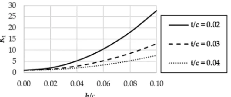
(I/A)cambered=K1(I/A)flat, whereK1=K1(t/c,h/c) (12) Icamberedwas obtained for the cambered plate-section using an analytical integration process known from basic solid-state mechanics [45]. As background information for the reader, the values ofK1are presented in Figure7for representative relative thickness and relative camber (h/c) values. For the fitted curves in Figure7,K1was calculated for fixedt/c values for uniform steps of 0.01h/cover the entireh/crange. In the blade design presented later,K1(t/c= 0.02;h/c= 0.08) = 18.07 was used, in accordance with the previously selected blade geometrical parameters.
Int. J. Turbomach. Propuls. Power2022,7, 2 11 of 23
Int. J. Turbomach. Propuls. Power 2022, 7, x FOR PEER REVIEW 11 of 23
Substituting Equations (11) and (12) into Equation (10), the first bending eigenfre- quency can be expressed as follows:
b 2 b b 2 2 1
B,1
56 . 0 12 56 .
0 K ta
a l K t
f = l = (13)
where Kb = Kb (t/c = 0.02; h/c = 0.08) = 1.23 is the blade mechanics coefficient. Case studies considering other t/c and h/c values can be carried out using Figure 7.
Figure 7. The value of K1 as a function of relative camber for various relative thicknesses.
4. PVS-Affected Rotor: An Exemplary Case Study
The aim of this section is to outline a design case study, resulting in a rotor suspected to be unfavorable in terms of noise and vibration due to PVS. Although several unfavor- able design cases of such kind can be intentionally generated, this paper intends to present a single, representative design example. The resultant rotor will be termed herein the PVS- affected rotor. Such a design aims to serve as a basis for the realization of a case study rotor that is expected to exhibit remarkable and experimentally well-detectable narrow- band signatures of PVS. By such means, the orders of the magnitude of harmfulness of PVS-related effects are to be quantified in future experiments on the PVS-affected rotor, in comparison with other rotors of comparative design. The features of the PVS-affected rotor are as follows:
(a) The rotor blading tends to exhibit a PVS of spanwise constant frequency, and thus, is theoretically presumed to realize large-scale, spatially coherent vortices over the dominant portion of the blade span. Such coherent vortices are assumed to cause spatially correlated, narrowband noise, as well as mechanical excitation over the dominant part of span at a given frequency. The condition of spanwise constant PVS frequency is therefore applied herein in a pessimistic aspect, although it is noted that the signature of PVS noise was observed by [19] even when PVS was confined to
~10% span near the tip of a single blade.
(b) The latter is presumed to provoke blade vibration, if the frequency of PVS coincides with the frequency of the firstbending mode of blade vibration.
4.1. Aerodynamics: Blade Design
To be able to design a fan for which the spanwise constancy of PVS frequency is ful- filled—thus satisfying Equation (14), presented later—first, typical dimensionless design and geometrical characteristics, representative of propeller-type fans, were systematically gathered and summarized in Table 3. Here, the authors stress that, in order to guarantee the validity of Equation (9), the blade chord along the blade span was fixed, so c(rb) = constant. The tendency toward keeping the chord constant along the span in the blade design is supported by the literature examples of [19,20]. Based on the well-known Cor- dier diagram [46] for turbomachines of favorable efficiency, axial flow fans have the spe- cific diameter and the specific speed within the approximate ranges of 1 ≤ δ ≤ 1.5 and 2 ≤ σ ≤ 3, respectively. These ranges correspond to the global total pressure rise coefficient and flow coefficient within the ranges of 0.05 ≤ Ψt ≤ 0.25 and 0.1 ≤ Φ ≤ 0.5, respectively.
Figure 7.The value ofK1as a function of relative camber for various relative thicknesses.
Substituting Equations (11) and (12) into Equation (10), the first bending eigenfre- quency can be expressed as follows:
fB,1 = 0.56 l2
r K1t2
12 ab= 0.56
l2 Kbt ab (13)
whereKb=Kb(t/c= 0.02;h/c= 0.08) = 1.23 is the blade mechanics coefficient. Case studies considering othert/candh/cvalues can be carried out using Figure7.
4. PVS-Affected Rotor: An Exemplary Case Study
The aim of this section is to outline a design case study, resulting in a rotor suspected to be unfavorable in terms of noise and vibration due to PVS. Although several unfavorable design cases of such kind can be intentionally generated, this paper intends to present a single, representative design example. The resultant rotor will be termed herein the PVS-affected rotor. Such a design aims to serve as a basis for the realization of a case study rotor that is expected to exhibit remarkable and experimentally well-detectable narrowband signatures of PVS. By such means, the orders of the magnitude of harmfulness of PVS-related effects are to be quantified in future experiments on the PVS-affected rotor, in comparison with other rotors of comparative design. The features of the PVS-affected rotor are as follows:
(a) The rotor blading tends to exhibit a PVS of spanwise constant frequency, and thus, is theoretically presumed to realize large-scale, spatially coherent vortices over the dominant portion of the blade span. Such coherent vortices are assumed to cause spatially correlated, narrowband noise, as well as mechanical excitation over the dominant part of span at a given frequency. The condition of spanwise constant PVS frequency is therefore applied herein in a pessimistic aspect, although it is noted that the signature of PVS noise was observed by [19] even when PVS was confined to ~10%
span near the tip of a single blade.
(b) The latter is presumed to provoke blade vibration, if the frequency of PVS coincides with the frequency of the first bending mode of blade vibration.
4.1. Aerodynamics: Blade Design
To be able to design a fan for which the spanwise constancy of PVS frequency is fulfilled—thus satisfying Equation (14), presented later—first, typical dimensionless design and geometrical characteristics, representative of propeller-type fans, were systematically gathered and summarized in Table3. Here, the authors stress that, in order to guarantee the validity of Equation (9), the blade chord along the blade span was fixed, soc(rb) = constant.
The tendency toward keeping the chord constant along the span in the blade design is supported by the literature examples of [19,20]. Based on the well-known Cordier diagram [46] for turbomachines of favorable efficiency, axial flow fans have the specific diameter and the specific speed within the approximate ranges of 1≤δ≤1.5 and 2≤σ≤3, respectively. These ranges correspond to the global total pressure rise coefficient and flow coefficient within the ranges of 0.05≤Ψt≤0.25 and 0.1≤Φ≤0.5, respectively. Thus, values in Table3fit to the Cordier diagram well. Regulation 327/2011/EU5 issued energy
Int. J. Turbomach. Propuls. Power2022,7, 2 12 of 23
efficiency requirements regarding fans in the EU [47], driven by motors with an electric input power between 125 W and 500 kW. According to this, the target total efficiency of an axial fan is 0.5≤ηt≤0.6 depending on the arrangement and input power. Considering a more economical operation, we are moving toward higher efficiency levels; therefore, ηt≈0.7 is chosen.
Table 3.Geometrical and material parameters of the blade for the PVS-affected rotor.
c/Dtip ν AR Ψt Φ N ηt δ σ
0.133 0.415 2.22 0.143 0.309 5 0.700 1.11 2.39
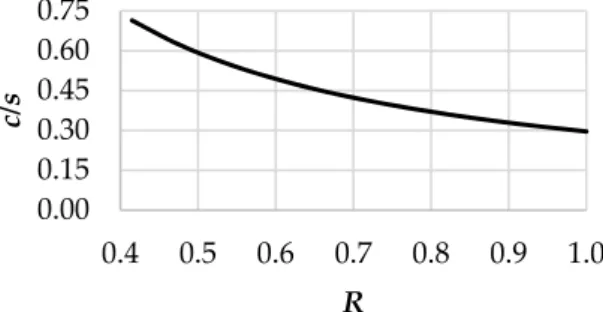
The first two parameters as well asNin Table3define the blade solidity from hub to tip. When calculating the solidity (c/s), it is found that it is below 0.7 along the entire radius of the blade even at the hub, as can be observed in Figure8. Therefore, according to [46] measurement data on isolated blade profiles—such as data included in Figure4in the case of a 8% cambered plate—can be applied in the present design of the PVS-affected rotor. In addition to the aerodynamic data in Figure4, the empirical data on PVS in [5,13]
are also related to isolated profiles, thus fitting to the low-solidity approach utilized herein.
Int. J. Turbomach. Propuls. Power 2022, 7, x FOR PEER REVIEW 12 of 23
Thus, values in Table 3 fit to the Cordier diagram well. Regulation 327/2011/EU5 issued energy efficiency requirements regarding fans in the EU [47], driven by motors with an electric input power between 125 W and 500 kW. According to this, the target total effi- ciency of an axial fan is 0.5 ≤ ηt ≤ 0.6 depending on the arrangement and input power.
Considering a more economical operation, we are moving toward higher efficiency levels;
therefore, ηt ≈ 0.7 is chosen.
Table 3. Geometrical and material parameters of the blade for the PVS-affected rotor.
c/Dtip ν AR Ψt Φ N ηt δ σ
0.133 0.415 2.22 0.143 0.309 5 0.700 1.11 2.39 The first two parameters as well as N in Table 3 define the blade solidity from hub to tip. When calculating the solidity (c/s), it is found that it is below 0.7 along the entire radius of the blade even at the hub, as can be observed in Figure 8. Therefore, according to [46]
measurement data on isolated blade profiles—such as data included in Figure 4 in the case of a 8% cambered plate—can be applied in the present design of the PVS-affected rotor. In addition to the aerodynamic data in Figure 4, the empirical data on PVS in [5]
and [13] are also related to isolated profiles, thus fitting to the low-solidity approach uti- lized herein.
Figure 8. Blade solidity as a function of dimensionless radius (R = r/rtip).
In what follows, preliminary design efforts are made for obtaining a rotor blading exhibiting PVS of spanwise constant frequency in order to fulfill the pessimistic condition outlined at the end of the Introduction. The PVS frequency can be expressed from Equa- tion (2) as follows:
const r
b r St U r
f = =
) (
) ) (
(
b b
* 0 b
PVS (14)
A nearly constant value of St* ≈ 0.19 was found for a 8% cambered plate for various Reynolds numbers and angles of attack in the present authors’ previous measurement campaign [13]. Keeping the uncertainty of the measurement-based St* data in mind, this value is in fair agreement with the literature-based data in Equation (2). St* = 0.19 was used for the calculation presented in the paper. In order to clarify the trend of the free- stream velocity, the velocity vectors are shown in Figure 9. Based on Figure 9, the square of the free-stream velocity can be written as follows [46]:
2 b b
b 2 b 2
0 2
) ) (
( ) ( )
(
−Δ
+
= c r
r u r c r
U x u (15)
where cx is the axial velocity component; u is the circumferential velocity; and Δcu is the increase of tangential velocity due to the rotor.
0.00 0.15 0.30 0.45 0.60 0.75
0.4 0.5 0.6 0.7 0.8 0.9 1.0
c/s
R
Figure 8.Blade solidity as a function of dimensionless radius (R=r/rtip).
In what follows, preliminary design efforts are made for obtaining a rotor blading exhibiting PVS of spanwise constant frequency in order to fulfill the pessimistic condi- tion outlined at the end of the Introduction. The PVS frequency can be expressed from Equation (2) as follows:
fPVS(rb) =St∗U0(rb)
b(rb) =const (14)
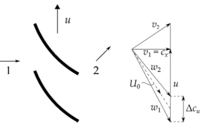
A nearly constant value ofSt*≈0.19 was found for a 8% cambered plate for various Reynolds numbers and angles of attack in the present authors’ previous measurement campaign [13]. Keeping the uncertainty of the measurement-basedSt* data in mind, this value is in fair agreement with the literature-based data in Equation (2).St* = 0.19 was used for the calculation presented in the paper. In order to clarify the trend of the free-stream velocity, the velocity vectors are shown in Figure9. Based on Figure9, the square of the free-stream velocity can be written as follows [46]:
U02(rb) =cx2(rb) +
u(rb)−∆cu(rb) 2
2
(15) wherecxis the axial velocity component;uis the circumferential velocity; and∆cuis the increase of tangential velocity due to the rotor.