Paper ID: ETC2021-546 Proceedings of 14th European Conference on Turbomachinery Fluid dynamics & Thermodynamics ETC14, April 12-16 2021; Gdansk, Poland
OPEN ACCESS
Downloaded from www.euroturbo.eu 1 Copyright © by the Authors
SEMI-EMPIRICAL DESIGN GUIDELINES FOR CONTROLLING THE VIBRATION AND NOISE OF LOW-SPEED AXIAL FANS DUE
TO PROFILE VORTEX SHEDDING
G. Daku – J. Vad
Department of Fluid Mechanics, Faculty of Mechanical Engineering, Budapest University of Technology and Economics, Bertalan Lajos u. 4 – 6., H-1111 Budapest, Hungary;
Email: daku@ara.bme.hu, vad@ara.bme.hu ABSTRACT
This paper presents a critical overview on worst-case design scenarios for which low-speed axial flow fans may exhibit an increased risk of blade resonance due to profile vortex shedding.
To set up a design example, a circular-arc-cambered plate of 8% relative curvature has been investigated in twofold approaches of blade mechanics and aerodynamics. For these purposes, the eigenfrequency of a plate of arbitrary camber has been expressed by modelling the fan blade as a cantilever beam. Furthermore, an iterative blade design method has been developed for pointing out the risky scenarios for which spanwise spatially coherent shed vortices, stimulating pronounced vibration and noise, may occur. Coupling these two approaches, cases for vortex- induced blade resonance have been set up. Opposing to this basis, design guidelines have been elaborated for avoiding such resonance. Based on approach presented herein, guidelines have also been developed for moderating the annoyance due to vortex shedding noise.
KEYWORDS
AXIAL FLOW FAN, BLADE VIBRATION, LOW TIP SPEED, PRELIMINARY FAN DESIGN, VORTEX SHEDDING
NOMENCLATURE Latin letters
A cross-section [m2] K1 preliminary design constant [-]
ab wave propagation speed = (E/ρb)1/2 [m/s] Kb blade mechanics coefficient [-]
AR aspect ratio = l/c [-] l blade span [m]
b transversal dist. between vortex rows [m] LDR lift-to-drag ratio = CL/CD [-]
CD drag coefficient [-] N blade count [-]
CL lift coefficient [-] n rotor speed [1/s]
c blade chord length [m] pt,is isentropic total pressure rise [Pa]
c/s blade solidity [-] R dimensionless radius = r/rtip [-]
cx axial velocity component [m/s] r radial coordinate [m]
cu increase of tangential velocity [m/s] Rec Reynolds number = cU0 /νa [-]
D rotor diameter [m] s blade spacing = 2rπ/N [m]
dTE trailing edge thickness [m] St Strouhal number [-]
E Young modulus [Pa] St* universal Strouhal number [-]
f dominant frequency [Hz] t profile thickness [m]
h maximum height of the camber line [m] t/c relative thickness [-]
h/c relative camber [-] u rotor circumferential velocity [m/s]
I second moment of area [m4] U0 free-stream velocity = (w1+w2)/2 [m/s]
K* empirical coefficient ≈ 1.2 [-] v absolute velocity component [m/s]
2
w relative velocity component [m/s] W dimensionless free-stream velocity [-]
Greek letters
α angle of attack [°] ρ density [kg/m3]
γ stagger angle [°] σ specific speed [-]
δ specific diameter [-] Φ global flow coefficient [-]
η efficiency [-] φ local flow coefficient [-]
Θ momentum thickness of blade wake [m] Ψ global pressure rise coefficient [-]
ν hub-to-tip ratio [-] ψ local pressure rise coefficient [-]
νa kinematic viscosity of air [m2/s]
Subscripts and superscripts
1 rotor inlet is isentropic
2 rotor outlet mid mid-span position
a air PVS profile vortex shedding
b blade t total
crit critical TE trailing edge
ef eigenfrequency tip blade tip
Abbreviations
CG center of gravity TE trailing edge
CFD Computational Fluid Dynamics VS vortex shedding PVS profile vortex shedding
INTRODUCTION AND OBJECTIVES
Vortex shedding (VS) from low-speed axial flow fan rotor blades has become of engineering relevance in the past decades. The VS phenomenon discussed in the paper – termed herein profile vortex shedding (PVS), and illustrated in Figure 1 – is not to be confused with trailing-edge-bluntness VS, which takes place past the blunt trailing edge (TE) of the blade profile, acting as the aft portion of a bluff body (Brooks et al., 1989). In the former literature, PVS is referred to as laminar-boundary- layer VS, because it can only occur if the boundary layer is initially laminar at least over one side of the blade profile. In this case, the initially laminar boundary layer being separated near or after mid- chord position, then reattaches at the vicinity of the TE – thus resulting in a separation bubble – and finally undergoes a laminar-to-turbulent transition. Moreover, the position and the size of the formed separation bubble play a key role in tonal PVS noise emission. Recently Yakhina at al. (2020) have published a detailed investigation about tonal TE noise radiated by low Reynolds number airfoils.
They observed that a precondition for tonal noise emission is the formed separation bubble being sufficiently close to the TE. PVS may occur within a certain Reynolds number range. Based on the literature (Lowson et al., 1994; Balla and Vad, 2019; Balla, 2020) a lower limit of Rec = 5·104 is assumed herein, while the upper limit is determined by the critical Reynolds number of the natural laminar-to-turbulent transition. As far as PVS is discussed for low-speed fans, as in the present paper, incompressible flow is considered by implying a Mach number of ≤ 0.3.
Figure 1. Profile vortex shedding (PVS)
Various models are available in the literature on the PVS phenomenon. In this paper, only the classic model by Tam (1973) and Wright (1974) is referred to, in order to provide a straightforward comprehensive interpretation on the mechanism. According to this model, PVS is related to a self- excited feedback loop. Due to the unstable laminar boundary layer, Tollmien-Schlichting instability waves are generated, then these waves travel downstream toward the TE where sound scattering
3
occurs, and acoustic waves are created. The acoustic waves propagate upstream to amplify the original instabilities. If appropriate phase conditions are fulfilled, the disturbances are amplified at some frequencies, thus closing the feedback loop. Later, a number of authors, e.g. Nash et al. (1999), carried out a critical revision on the aforementioned feedback loop model. PVS may generate vibration on the blade. As the studies by Ausoni et al. (2006) suggest, the mechanisms of periodic vortex shedding and periodic blade vibration may mutually be coupled at a blade eigenfrequency, within a “lock-in” phenomenon.
The difference between PVS and TE-bluntness VS in their physical mechanisms manifests itself in scaling techniques and values of Strouhal number being also different.
For TE-bluntness vortex shedding (Roger and Moreau, 2010):
20 . 0 / 0
TE TE
TE f d U
St (1)
For PVS (Yarusevych et al., 2009; Yarusevych and Boutilier, 2011):
18 . 0 / 0
PVS
* f b U
St (2)
where f is the dominant frequency of the two types of VS; dTE is the TE thickness; U0 is the free- stream velocity; and b is the distance between vortex rows. Yarusevych et al. (2009) suggested the appellation of a “universal” Strouhal number St*, as specified in Eq. (2), because they found it is universally valid for symmetrical, relatively thick NACA airfoils for certain ranges of Reynolds number and angle of attack. However, these airfoils are not widely used in axial fan application;
therefore, the present authors have extended the proposed St* definition as follows. Systematic wind tunnel experiments were performed on blade section models typical for low-speed axial fans, using a one-component hot-wire probe. Based on the measured f and b values, the authors confirmed the validity of St* also for asymmetrical profile geometries, such as 8% cambered plate and RAF-6E profiles, in a quasi-2D experimental analysis (Daku and Vad, 2020). Thus, the available experimental database on PVS frequency (Balla and Vad, 2019) has been extended.
From an engineering point of view, the practical aspects of PVS are remarkable in two ways:
vibration and noise. The impact of PVS on both noise and vibration is presumed to be pronounced when extensive, coherent vortices are shed with uniform frequency along a dominant portion of the blade span. On the one hand, PVS creates a periodically fluctuating force normal to the chord, increasing the risk of blade vibration. On the other hand, VS appears as the primary source of aeroacoustics noise of low-speed axial flow fans (Lee et al., 1993; Sasaki, 2005; Dou et al., 2016).
Hence, it is an important engineering objective to control the vibration and noise of low-speed axial fans due to PVS.
However, measurements on PVS in the literature are mostly related to isolated, steady airfoils (Paterson et al., 1973; Arbey and Bataille, 1983; Yarusevych et al., 2009; Yarusevych and Boutilier, 2011; Yakhina at al., 2020; Daku and Vad, 2020). Only a few studies dealt with PVS in the case of rotating blades of asymmetrical profiles being characteristic for realistic axial fans. Longhouse (1976) detected PVS noise on an axial fan of four cambered plate blades with constant blade chord.
Nevertheless, except for a small segment (~10%) of the span of one blade in near-tip region, the PVS noise was suppressed by aft-chord serrations. Furthermore, the spanwise variation of free-stream velocity tended to broaden the noise signature of PVS, thus acting against a remarkable, well- detectable tonal PVS character. Grosche and Stiewitt (1978) examined a 4-bladed propeller-type axial fan rotor with moderate sweep and twist. They observed PVS noise at α ≈ 4° angle of attack, viewed in the rotating frame of reference near the blade tip, for three different Reynolds numbers based on the chord length (Rec = 9·104, 1.3·105, 2.6·105). All of the aforementioned observations - both the isolated blade profile and rotor consideration – suggest that the following blade features tend to increase the inclination for occurrence of well-detectable tonal PVS: high aspect ratio (AR), low solidity, moderate twist, and constant blade chord. These parameters are typical for propeller-type fans (Harris, 2006). Such propeller-type fans, where low-solidity is characteristics over a significant portion of the span, have been designed, for instance, by Castegnaro et al. (2017) and Masi and Lazzaretto (2019).
4
In order to moderate the harmful noise and vibration effects due to PVS, pessimistic design scenarios are to be systematically discovered first, for which such harmful effects are pronounced.
For this purpose, the present authors aim to find out those design characteristics, for which PVS results in coherent vortex structures tending toward a uniform frequency along the full blade span.
Furthermore, these design characteristics have been coupled with rotor dynamics considerations.
Since, if the dominant frequency of PVS coincides with an eigenfrequency of the blade, resonance may occur, which may cause the axial fan rotor to vibrate. Such vibration may lead to rotor imbalance or break down of the blades. Based on this, an unfavourable design case has been set up in terms of both operational and geometrical characteristics, for which PVS demonstrates an increased risk of blade resonance. Taking the rotor of such unfavourable design case – termed hereafter PVS-affected rotor – as reference, approximate semi-empirical design guidelines can be elaborated already in the preliminary design phase for avoiding PVS-induced resonance. The design guidelines for noise reduction, reported in Daku and Vad (2020), have also been further developed toward a more detailed model, as illustrated in the paper.
BLADE MECHANICS Eigenfrequency
In order to build up a straightforward model for the interaction of the blade and the fluctuating aerodynamic force due to PVS, some simplifications must be introduced. First of all, a circular-arc- cambered plate of 8% relative curvature have been chosen as a blade profile for several reasons:
a) At moderate Reynolds numbers and angles of attack (α) cambered plate produces reasonably high CL, being competent with an airfoil profile, i.e. RAF-6E (Balla and Vad, 2018), thus enabling the design of blades of relatively high specific performance, i.e. utilizing the loading capability of the blade sections.
b) At 8 % relative curvature, the lift-to-drag (LDR) is near the maximum among the cambered plates of various relative camber, thus enabling the design for reasonably high efficiency (Wallis, 1961).
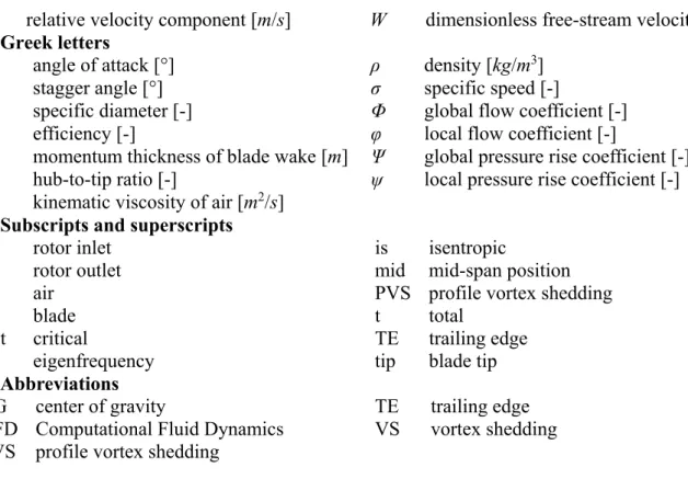
c) In accordance with the aforementioned practical aspects, it is a cambered plate of 8 % relative camber for which hot-wire measurement data have been made available by the present authors on PVS at different free-stream velocities and angles of attack (Daku and Vad, 2020). As illustration, Figure 2 shows CL, CD, and LDR values as a function of angle of attack for 8% cambered plate.
Figure 2. Lift and drag coefficients and lift-to-drag ratios as a function of angle of attack for 8% cambered plate at Rec = 3ꞏ105 (Wallis, 1961)
5
Secondly, the fan blade is presumed to consist of geometrically identical blade sections along the full span. This means that the blade chord c, plate thickness t, and height of the camber line h are constants (Figure 3). The measurement data presented by Wallis (1961), shown in Figure 2, are related to a relative thickness (t/c) of 2%. This value is representative in fan manufacturing; therefore, t/c has been fixed at 2% for the present investigations.
Figure 3. Circular-arc-cambered plate (8% relative camber)
Finally, it has been assumed that all degrees of freedom of the blades at the hub, i.e. at the blade root, are constrained. This is a reasonable approximation e.g. if sheet metal blades connect to the hub with a welded joint; or, in the case of polymer material, if the entirety of the hub and blading assembly is injection-moulded as a single product. The simplifications above enable us to model the blade as a cantilever beam (or clamped beam) subjected to free vibration. In order to provide a straightforward and comprehensive approach in preliminary design, avoiding any need for numerical computation at the present phase of research, the analytically expressed eigenfrequencies are considered, as specified in Bohl (1991) and Bohl and Elmendorf (2013). Out of such analytical solutions, the lowest eigenfrequency in Eq. (3), related to the “1st order bending mode” shown in Figure 4, is taken herein as illustrative example for the analytical treatment elaborated by the authors. The reasonability of this choice is justified as follows. PVS is assumed to exhibit pressure fluctuations over the blade suction and pressure surfaces, causing chord-normal forces. Assuming spanwise spatially coherent shed vortices, the resultant fluctuating forces are in phase over the entire span. Furthermore, PVS and the related forces may occur farther upstream of the TE (conf. Yarusevych and Boutilier, 2011). The resultant swinging pattern is as in Fig. 4. However, the simple analytical treatment can be easily extended to higher-order bending modes and also to torsional modes upon demand – being the subject of future research –, using the analytical formulae e.g. in Bohl (1991).
b ef 2
56 . 0
E A I
f l (3)
where l is the radial extension of blade from hub to tip, i.e. the blade span; I is the second moment of area with respect to the axis being parallel to the chord, and fitting to the center of gravity (CG) of the blade section; A is the cross-sectional area of the blade profile; E is the Young modulus; and ρb is the density of the blade material. The last term on the right-hand side of Eq. (3), being the square root of the specific modulus E/ρb, is termed herein wave propagation speed, and denoted as ab. Which is actually the acoustic wave propagation speed in a long one-dimensional fictitious beam made of the blade material.
Figure 4. Cantilever beam subjected to free vibration (perpendicular to the blade chord) Second Moment of Area
The purpose of the present section is to demonstrate how the I/A term can be related to the basic geometrical characteristics of the circular-arc-cambered plate blade (c, h/c, t/c), creating a direct relationship between the first eigenfrequency and the geometrical parameters of the blade. However, no closed analytical relationship exists in the literature for such purpose. Therefore, an alternative
6
method must be found to express the second term of the right-hand side of Eq. (3) with use of blade geometrical parameters such c, h, and t. As a first step, the second moment of area of a cambered plate and a flat plate with same geometrical parameter (t, c) have been compared to each other.
The quotient of the second moment of area and the cross-section, in case of a flat plate:
I Aflat (ct3/12) (ct)t2 12 (4) For a cambered plate:
I A cambered K1
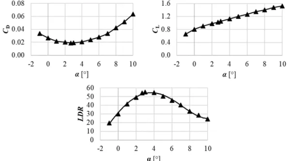
I A flat , where K1 = K1 (t/c, h/c) (5)Icambered has been obtained for cambered plate cross-section using an analytical integration process known from basic solid state mechanics (Beer et al., 2016). As background information for the reader, the values of K1 are presented in Figure 5 for representative relative thickness and relative camber (h/c) values. For the fitted curves in Fig. 5, K1 has been calculated for fixed t/c values for uniform steps of 0.01 h/c over the entire h/c range. In the blade design presented later, K1 (t/c = 0.02; h/c = 0.08) = 18.07 has been used, in accordance with the previously selected blade geometrical parameters.
Substituting Eq. (4) and (5) into Eq. (3), the eigenfrequency can be expressed as follows:
b 2 b
b 2 2 1
ef
56 . 0 12
56 .
0 K ta
a l K t
f l (6)
where Kb = Kb (t/c = 0.02; h/c = 0.08) = 1.23 is the blade mechanics coefficient. Case studies considering other t/c and h/c values can be carried out using Figure 5.
Figure 5. The value of K1 as a function of relative camber for various relative thicknesses PVS-AFFECTED ROTOR
The aim of this section is to outline a design case study, resulting in a rotor, suspected to be unfavourable in terms of noise and vibration due to PVS. Although several unfavourable design cases of such kind can be intentionally generated, this paper intends to present a single, representative design example. The resultant rotor will be termed herein PVS-affected rotor. Such design aims to serve as basis for realization of a case study rotor that is expected to exhibit remarkable and experimentally well-detectable narrowband signatures of PVS. By such means, the orders of magnitude of harmfulness of PVS-related effects are to be quantified in future experiments on the PVS-affected rotor, in comparison with other rotors of comparative design. The features of the PVS- affected rotor are as follows:
a) The rotor blading tends to exhibit PVS of spanwise constant frequency, and thus, is theoretically presumed to realize large-scale, spatially coherent vortices over the dominant portion of blade span. Such coherent vortices are assumed to cause spatially correlated, narrowband noise, as well as mechanical excitation over the dominant part of span at a given frequency. The condition of spanwise constant PVS frequency is therefore applied herein in a pessimistic aspect, although it is noted that the signature of PVS noise has been observed by Longhouse (1977) even when PVS was confined to ~ 10 % span near the tip of a single blade.
7
b) The latter is presumed to provoke blade vibration, if the frequency of PVS coincides with the first eigenfrequency of the blade.
a) Aerodynamics: blade design
To be able to design a fan for which the spanwise constancy of PVS frequency is fulfilled – thus satisfying Eq. (7), presented later – first, typical dimensionless design and geometrical characteristics being representative for propeller-type fans have systematically been gathered and summarized in Table 1. Here, the authors stress that, in order to guarantee the validity of Eq. (3), the blade chord along the blade span has been fixed, c(rb) = constant. The tendency toward keeping the chord constant along the span in blade design is supported by the literature examples of Longhouse (1976) and Grosche and Stiewitt (1978). Based on the well-known Cordier diagram (Carolus, 2003) for turbomachines of favourable efficiency, axial flow fans have the specific diameter and the specific speed within the approximate ranges of 1 ≤ δ ≤ 1.5 and 2 ≤ σ ≤ 3, respectively. These ranges correspond to the global total pressure rise coefficient and flow coefficient within the ranges of 0.05
≤ Ψt ≤ 0.25 and 0.1 ≤ Φ ≤ 0.5, respectively. Thus, values in Table 1 fit to the Cordier diagram well.
Regulation 327/2011/EU5 issued energy efficiency requirements regarding fans in the EU, driven by motors with an electric input power between 125W and 500 kW. According to this, the target total efficiency of an axial fan is 0.5 ≤ ηt ≤ 0.6 depending on the arrangement and input power. Considering more economical operation, we are moving toward to higher efficiency levels, so ηt ≈ 0.7 is chosen.
Table 1. Dimensionless design parameters
c/Dtip ν AR Ψt Φ N ηt δ σ
0.133 0.415 2.22 0.143 0.309 5 0.700 1.11 2.39
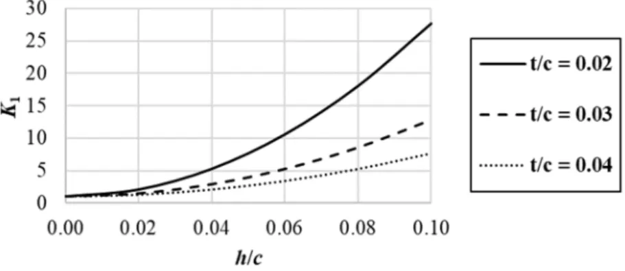
The first two parameters as well as N in Table 1 define the blade solidity from hub to tip. When calculating the solidity (c/s), it is found that it is below 0.7 along the entire radius of the blade even at the hub, as it can be seen in Figure 6. Therefore, according to Carolus (2003), measurement data on isolated blade profiles – such as data included in Figure 2 in case of a 8% cambered plate – can be applied in the present design of the PVS-affected rotor. In addition to the aerodynamic data in Figure 2, the empirical data on PVS in Balla and Vad (2019) and Daku and Vad (2020) are also related to isolated profiles, thus fitting to the low-solidity approach utilized herein.
Figure 6. Blade solidity as a function of dimensionless radius (R = r/rtip)
In what follows, preliminary design efforts are made for obtaining a rotor blading exhibiting PVS of spanwise constant frequency in order to fulfill the pessimistic condition outlined at the end of the Introduction. The PVS frequency can be expressed from Eq. (2) as follows:
const r
b r St U r
f
) (
) ) (
(
b b
* 0 b
PVS (7)
A nearly constant value of St* ≈ 0.19 was found for a 8% cambered plate for various Reynolds numbers and angles of attack in the present authors’ previous measurement campaign (Daku and Vad,
8
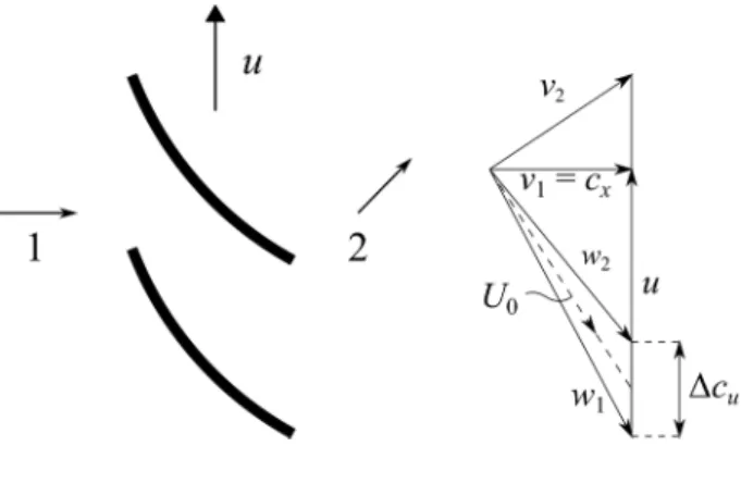
2020). Keeping the uncertainty of the measurement-based St* data in mind, this value is in fair agreement with the literature-based data in Eq. (2). St* = 0.19 was used for the calculation presented in the paper. In order to clarify the trend of the free-stream velocity, the velocity vectors are shown in Figure 7. Based on Figure 7, the square of the free-stream velocity can be written as follows (Carolus, 2003):
2 b b
b 2 b 2
0 2
) ) (
( ) ( )
(
c r
r u r c r
U x u (8)
where cx is axial velocity component; u is the circumferential velocity; and Δcu is the increase of tangential velocity due to the rotor.
Figure 7. Velocity triangles
From Eq. (8) the square of the dimensionless free-stream velocity can be expressed as follows:
) 4 (
) ) (
) (
( 2 t,is 2 2
2 tip
b 2
0 W R
R R R u R
r
U
(9)
where W is the dimensionless free-stream velocity; φ = cx(rb)/utip is the local flow coefficient; R is dimensionless radius; and t,is is the local total isentropic pressure rise coefficient. As a brief approximation, the circumferential velocity u, representing a solid body rotation, dominates in U0. Therefore, U0 tends to approximately linearly increase with R. In a refined calculation, presented later, cx/utip and Δcu/utip are to be taken into account when obtaining U0.
In order to provide a spanwise constant fPVS, b(rb) is tend to increase along the span by such means that its increase matches with the spanwise increase of U0.
According to Balla and Vad (2019), the distance between vortex rows normalized by the blade chord is:
c r K Θ c
r
b( b) * ( b) (10)
where K*≈1.2 is an empirical coefficient (Balla, 2020); and Θ is the momentum thickness of the blade wake. According to Fathy et al. (1977) and Lee et al. (1993), the drag coefficient can be written as:
c r r Θ
C 2 ( )
)
( b b
D (11)
Thus b can be expressed as follows:
2 ) ) (
( b *CD rb K
c r
b (12)
From Eq. (12) it can be seen that a spanwise increase of b is to be achieved via spanwise increase of CD. Based on Figure 2, CD(Rmid) = 0.032 has been chosen, which corresponds to α = 6.8°. In the design of the PVS-affected rotor, the following range of CD(R) was used: 0.0196 ≤ CD ≤ 0.0410.
Furthermore, as Figure 2 illustrates, the CD data within the design range are assigned to α data, and via such assignment, they also determine the design range for the local lift coefficient CL(α).
9
Therefore, the lift-to-drag ratio LDR(α) = CL/CD data are also obtained for the entire design range, incorporating the data at Rmid. Thus, each of CD(Rmid), CL(Rmid), and LDR(Rmid) are available, which quantities will play an important role in the further investigation of the PVS-affected rotor, as presented later.
Iterative method
In order to provide a spanwise constant fPVS, the nearly linear spanwise increase of U0 is to be matched in blade design with the spanwise increase of CD. To be able to design such a fan, an iterative method has been elaborated as follows, using the data in Table 1 as a basis. Taking Eq. (9), as an initial guess, the increase of tangential velocity due to the rotor is neglected, so W(R) can be calculated from only the local flow coefficient φ = cx(rb)/utip and the dimensionless radius corresponding to the rigid body rotation. In the present methodology, uniform axial inlet condition is assumed, cx(rb)/utip = constant. Furthermore, based on Carolus (2003) as an approximation, the change of meridional – i.e.
axial – velocity is neglected through the rotor. Above imply that spanwise constant axial velocity is presumed, as a brief approximation.
As a next step, based on the value of W(Rmid)/CD(Rmid), the drag coefficients are determined along the blade span. As described earlier, the CD(R), α(R) and CL(R) data are assigned to each other, via Figure 2. As a next stage of the design, Δcu/utip can be expressed from the simplified work equation of an elemental rotor:
) (
) ( ) 2
) (
( 0 b
b b L
b U r
r r c
r C s
c u (13)
where s = 2rbπ/N is the blade spacing. With the knowledge of Δcu(R)/utip, the local isentropic pressure rise coefficient t,is(R) can be expressed from the Euler equation of turbomachines:
) ( ) ( )
( b a b b
is
t, r u r c r
p u
(14)
where Δpt,is is the isentropic total pressure rise, and ρa is the density of air. This computed t,is(R) is then substituted into Eq. (9) for calculating a new approximation of W(R) in the next iteration loop.
Fast convergence is obtained in 2 to 3 iteration loops. The results are judged to be converged if the relative difference in t,is(R) for the consecutive iteration steps becomes less than 2%.
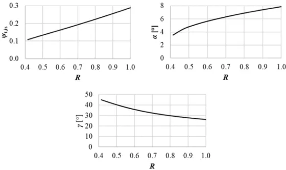
A feature of the iterative method is that t,is(R) and α(R) are actually the results of the design process. The spanwise distributions of the calculated quantities are shown in Figure 8, where γ(R) is stagger angle measured from the circumferential direction. Annulus-averaging of t,is(R) represents the global isentropic total pressure rise obtained as Ψt/ηt using the data in Table 1.
Figure 8. Calculated distributions t,is(R), α(R) and γ(R) as a function of R
10
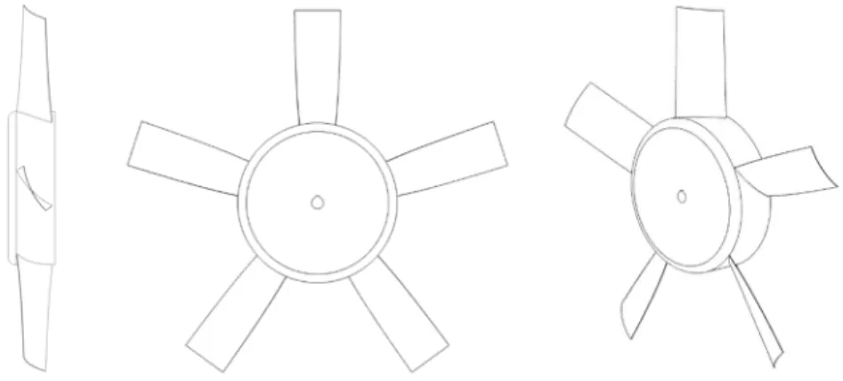
Figure 9 represents the proportionate three-dimensional model of the designed PVS-affected fan.
The rotor has a realistic, common geometry, being representative for propeller-type axial flow industrial fans. The blade geometry is in accordance with the fact that, as manufacturing simplification, low-speed axial fan blades of cost-effective manufacturing can be made from a plate of spanwise constant chord, being rolled in such a way that spanwise constant camber and moderate twist occurs.
Figure 9. The PVS-affected fan rotor b) Mechanically or acoustically unfavourable design cases
In order to set up mechanically unfavourable design cases, representing a coincidence of the frequency of PVS with the first eigenfrequency of the blade, U0 and b in Eq. (7) are necessary to be expressed. However, b has been previously expressed as shown in Eq. (10). Therefore, it is only necessary to deal with U0. Based on Eqs. (13) and (14), the free-stream velocity can be written as follows:
) ( ) (
) ( ) ( ) 2
(
b L b a
b b is t, b
0 u r cC r
r s r r p
U
(15)
Thus the PVS frequency can be expressed from Eqs. (7), Eq. (12) and Eq. (15):
c r C r K u
r s r C c
r St p
r
f ( )
2 ) (
) ( ) (
) ( ) 2
(
b D
* b b b L a
b is
* t, b
PVS
(16)
With the use of s(rb)/u(rb ) = (2rbπ/N)/(2rbπn) =1/(nꞏN) and CD = CL/LDR Eq. (16) can be written as follows:
c r C K
r LDR n
N r C c
r St p
r
f ( )
) ( 1 2
) (
) ( ) 2
(
b L
* b b
L a
b is
* t, b
PVS
(17)
where N is the blade count; and n is the rotor speed. The right-hand side of Eq. (17) can be rearranged according to Eq. (18) in the following way: In the first term, the global aerodynamic performance characteristics are grouped. The second term represents the operational condition of the rotor. In the third term, the basic parameters of the blade geometry are gathered. The fourth term represents the aerodynamics parameters of the elemental blade section. Finally, the last term incorporates the empirics and coefficients.
*
*
b 2 L
b 2
a b is t, b
PVS
4 ) (
) ( 1
) 1 ) (
( K
St r
C r LDR c N n r r p
f
(18)
In order to obtain generalized conclusions and trends, dimensionless quantities and groups must be introduced. It should be emphasized that PVS frequency is constant along the blade span due to the presented fan design method. Therefore, any characteristic taken at an arbitrary rb radius can be replaced by the same characteristic taken at Rmid. Furthermore, as a brief approximation ηt(rb) = ηt(Rmid) ≈ constant is presumed. With respect to the foregoing, the first term on the right-hand side of Eq. (18) can be expressed:
11 2 ) ( ) (
) ) (
( )
( tip2
t mid t mid t a
mid t a
mid is t, a
b is
t, Ψ R u
R R R p
p r
p
(19)
where utip=Dtipπn is the tip circumferential speed. The second and the third terms can be written as follows:
tip 2 tip tip 2
tip 2
1 1
1 1
1 1 1
s c u N D c
D n N c
n
(20)
Thus Eq. (18):
*
*
mid 2 L
mid 2
tip tip mid t
mid t
*
*
mid 2 L
mid 2
tip tip 2 tip t
mid t mid PVS
2 ) (
) ( )
( ) ( 4
) (
) ( 1 2
) ) (
( K
St R
C R LDR c
s u R
R Ψ K
St R
C R LDR c u
s R u
R Ψ
f (21)
As it has been outlined before, the mechanically unfavourable design case is considered, when spanwise constant PVS frequency coincides with the first eigenfrequency of the fan blade posing an increased risk of blade resonance:
ef PVS const f
f (22)
If Eq. (21) and Eq. (6) are substituted in the right-hand side and the left-hand side of Eq. (22), respectively, the following equation can be obtained:
b 2 b
*
*
mid 2 L
mid 2
tip tip mid t
mid
t 2 0.56
) (
) ( )
( )
( K ta
l K
St R
C R LDR c
s u R
R
Ψ
(23)
After rearrangement, Eq. (23) can be written in the following dimensionless from:
*
* b
mid mid 2 L 2 tip mid
t mid t b tip
2 56 . 0 ) (
) ( 1
) (
) (
St K K R LDR
R C AR s
c c t R Ψ
R a
u
(24)
Eq. (24) provides a means for calculating the critical utip/ab velocity ratio for which PVS results in blade resonance, if the nondimensional characteristics - valid for an entire PVS-affected rotor family under survey - are substituted into the right-hand side of the equation. With the knowledge of the blade material, ab can be obtained (conf. Eq. (3) and the paragraph below), and thus, the critical utip value can be computed. Hence, critical rotor diameter X rotor speed data couples can be discovered for an entire rotor family, consisting of rotors of various diameters and speeds.
If the rotor diameter and the nominal rotor speed is fixed for further defining a specific case study, the resultant, nominal utip value can be compared to the aforementioned critical one. Thus, it can be judged whether a risk of blade resonance may occur by changing the rotor speed, e.g. via a frequency converter. Furthermore, if the rotor diameter and the rotor speed are fixed, all dimensional quantities can be calculated, with the knowledge of nondimensional data in Table 1 as well as on the right-hand side of Eq. (18). This makes possible the calculation of fPVS, using Eq. (18), for acoustics evaluation.
By such means, the third-octave band incorporating PVS can be identified and critically evaluated.
For this purpose, the A-weighting graph (Norton and Karczub, 2003) is to be considered. The plateau of the A-weighting graph represents the most sensitive part of human audition. Keeping fPVS away from this plateau in blade design, by selecting the appropriate operational and geometrical characteristics, gives a potential for moderating the impact of fan noise on humans. If such design intent cannot be realized for modifying fPVS, the PVS phenomenon in itself is to be suppressed, necessitating modifications in the blade layout, e.g. boundary layer tripping. However, such modifications are to be treated with criticism since e.g. boundary layer tripping may undermine the performance of the fan (Lowson et al., 1994). Such undesired effects justify the present intent by the authors to accept the occurrence of PVS but “mistune” it toward uncritical frequencies by simple preliminary design means, as a first approach. Such mistuning, being beneficial from both vibration and noise points of view, is to be performed in preliminary blade design by the negation – i.e.
avoidance – of the worst-case design and operational scenarios represented by PVS-affected rotors.
For this reason, setting up guidelines for the worst-case design scenarios is of practical value.
12
CALCULATION EXAMPLE FOR THE DESIGNED ROTOR
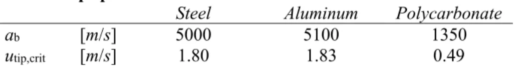
First, based on Eq. (24) and data in Table 1 being specific for the PVS-affected rotor designed herein, the critical tip speeds have been computed for various blade materials, which means different values of ab in terms of the calculation process. The calculated values are summarized in Table 2.
Table 2. Critical rotor tip speeds
Steel Aluminum Polycarbonate
ab [m/s] 5000 5100 1350
utip,crit [m/s] 1.80 1.83 0.49
Based on Table 2, it can be concluded that in the present case study, the critical tip speed is sufficiently low for making these cases irrelevant to blade resonance point of view for the 1st order bending mode (Fig. 4). Namely, only unpractically low rotor diameters D and / or rotor speeds n would result in coincidence of the fPVS and fef [Eq. (3)] values for the presented case study.
Furthermore, the lower the tip speed, the lower the fluctuating force causing vibration. However, the risk of blade vibration cannot be excluded for other design cases, characterized by modified data in Table 1; and for other – i.e. bending and torsional – modes of vibration. Therefore, an important future task - as part of the ongoing research project – is to systematically explore the cases (operational, geometrical, and material characteristics) being risky from resonance point of view. The methodology presented herein can be generally applied for such systematic studies.
As second part of the calculation example, the rotor diameter and rotor speed have been fixed as follows: Dtip = 0.900 m, n = 1450 1/min. Such values are relevant in industrial ventilation. They result in utip = 68.3 m/s. Considering data in Table 2 as well as previously fixed further parameters, additional quantities required to calculate the PVS frequency according to Eq. (21) have been derived.
The values of the computed quantities are presented in Table 3.
Table 3. PVS frequency for a n = 1450 1/min axial flow fan
Dtip c CL(Rmid) LDR(Rmid) stip fPVS
0.900 m 0.120 m 1.30 43.5 0.565 4520 Hz
The calculated PVS frequency falls within the third-octave band of middle frequency of 4.5 kHz.
Thus, it approximates the plateau of the A-weighting graph. Therefore, the related noise may cause increased annoyance for a human observer. However, by modifying the design parameters, the axial fan can be redesigned to keep the PVS frequency away from the plateau of the A-weighting graph, based on the presented computation. The systematic exploration of the advantageous parameter modifications, while finding reasonable compromises with other design perspectives, is also a future task.
CONCLUSIONS
Based on the semi-empirical model in literature, the pessimistic design condition of spanwise constant PVS frequency has been determined from aerodynamic approach. To fulfil this condition, an iterative fan design method has been elaborated, resulting in a design case study of a PVS-affected rotor. The frequency of PVS can be computed with the knowledge of the global operational and geometrical characteristics of an axial fan. A calculation process for determining the eigenfrequency of a circular-arc-cambered plate blade has been presented. By combining these two approaches, guidelines can be formulated, already in the preliminary design phase, for the following.
a) The critical tip speed that may cause resonance can be estimated for various blade materials, according to Eq. (24).
b) On the basis of a), the critical rotor speed n can be calculated for axial fans of known diameter.
Thus, it can be judged whether a risk of blade resonance may occur by changing the rotor speed.
13
c) The expected PVS frequency can be determined by knowing the rotor speed of the fan.
Therefore, the adverse acoustic effect of PVS can be forecasted on the basis of the A-weighting graph.
d) Opposing to the pessimistic design scenarios, redesign efforts are to be made for moderating / avoiding blade resonance and / or noise annoyance. Such efforts incorporate actions against the constancy of PVS frequency along the span. Systematic redesign scenarios as well as comparative experiments – also incorporating pessimistic, PVS-affected rotor cases – are to be realized in the future for validating the methodology presented herein. The design aspects related to PVS are to be investigated in the future via studies on 2D – i.e. rectilinear – blade models as well as on truly 3D rotor blade geometries – being unavoidable for full consideration of realistic rotor flow effects –, by concerted means of Computational Fluid Dynamics (CFD), analytical mechanics, finite-element mechanical computations, and experimentation. Such studies will also serve for exploration of the effects of assumptions and simplifications made in the method presented herein.
ACKNOWLEDGEMENTS
This work has been supported by the Hungarian National Research, Development and Innovation (NRDI) Centre under contract No. NKFI K 129023. The research reported in this paper and carried out at BME has been supported by the NRDI Fund (TKP2020 IES, Grant No. BME-IE-WAT and TKP2020 NC, Grant No. BME-NCS) based on the charter of bolster issued by the NRDI Office under the auspices of the Ministry for Innovation and Technology. The contribution of Gábor DAKU has been supported by Gedeon Richter Talent Foundation (registered office: 1103 Budapest, Gyömrői út 19-21.), established by Gedeon Richter Plc., within the framework of the “Gedeon Richter PhD Scholarship".
REFERENCES
Arbey, H., Bataille, J., (1983). Noise generated by airfoil profiles placed in a uniform laminar flow. Journal of Fluid Mechanics, 134, pp. 33-47.
Ausoni, P., Farhat, M., Bouziad, Y., Kueny, J-L., Avellan, F., (2006). Kármán vortex shedding in the wake of a 2D hydrofoil: Measurement and numerical simulation. IAHR Int. Meeting of WG on Cavitation and Dynamic Problems in Hydraulic Machinery and Systems, Barcelona, 28-30 June.
Balla E., Vad J., (2018). Lift and drag force measurements on basic models of low-speed axial fan blade sections. Proceedings of the Institution of Mechanical Engineers, Part A: Journal of Power and Energy, 233(2), pp. 165-175.
Balla, E., Vad, J., (2019). A semi-empirical model for predicting the frequency of profile vortex shedding relevant to low-speed axial fan blade sections, Proc. 13th European Conference on Turbomachinery Fluid Dynamics & Thermodynamics (ETC13), Lausanne, Switzerland. Paper ID:
ETC2019-311.
Balla, E., (2020). Aerodynamic and aeroacoustic behavior of axial fan blade sections at low Reynolds numbers. Ph.D. dissertation, Department of Fluid Mechanics, Faculty of Mechanical Engineering, Budapest University of Technology and Economics, Budapest
Beer, F. P., Johnston, E. R., Mazurek, D. F., (2016). Vector Mechanics for Engineers:
Statics (11th ed.). New York: McGraw-Hill, pp. 485-572.
Bohl W., (1991). Strömungsmaschinen, Vogel Buchverlag, Germany
Bohl, W., Elmendorf, W., (2013). Strömungsmaschinen 2: Berechnung und Konstruktion (2nd ed.), Kamprath-Reihe: Vogel Buchverlag, Germany
Brooks, T. F., Pope, D. S., Marcolini, M. A., (1989). Airfoil self-Noise and prediction, NASA Ref.
Publication 1218.
Carolus T., (2003). Ventilatoren. Wiesbaden: B. G. Teubner Verlag.
Castegnaro, S., Masi, M., Lazzaretto, A., (2017). Preliminary experimental assessment of the performance of rotor-only axial fans designed with different vortex criteria, Proc. 12th European
14
Conference on Turbomachinery Fluid Dynamics & Thermodynamics (ETC12), Stockholm, Sweden.
Paper ID: ETC2017-055.
Daku, G., and Vad, J., (2020). Experiment-based preliminary design guidelines for consideration of profile vortex shedding from low-speed axial fan blades. ASME Paper GT2020-14214
Dou, H., Li, Z., Lin, P., Wei, Y., Chen, Y., Cao, W., He, H., (2016). An improved prediction model of vortex shedding noise from blades of fans. Journal of Thermal Science, 25(6), pp. 526-531.
Fathy, A., Rashed, M. I., Lumsdaine, E., (1977). A theoretical investigation of laminar wakes behind airfoils and the resulting noise pattern, Journal of Sound and Vibration, 50(1), pp. 133-144.
Grosche, F., Stiewitt, H., (1978). Investigation of rotor noise source mechanisms with forward speed simulation. AIAA Journal, 16, pp. 1255–1261.
Harris, C., M., (2006). Dictionary of architecture and construction. McGraw-Hill Education.
Lee, C., Chung, M. K., Kim, Y. H., (1993). A prediction model for the vortex shedding noise from the wake of an airfoil or axial flow fan blades. Journal of Sound and Vibration, 164(2), pp. 327-336.
Longhouse, R. E., (1977). Vortex shedding noise of low tip speed, axial flow fans. Journal of Sound and Vibration, 53, pp. 25–46.
Lowson M., Fiddes S., Nash E., (1994). Laminar Boundary Layer Aeroacoustic Instabilities, In:
Proceedings of the 32nd Aerospace Sciences Meeting and Exhibit, Reno, NV, USA, 10–13 January.
Masi, M., Lazzaretto, A., (2019). A new practical approach to the design of industrial axial fans: tube- axial fans with very low hub-to-tip ratio. ASME. Journal of Engineering for Gas Turbines and Power, 141(10): 101003.
Nash E., Lowson M., McAlpine A., (1999). Boundary-layer instability noise on aerofoils. Journal of Fluid Mechanics, 382, pp. 27–61.
Norton, M., Karczub, D., (2003). Fundamentals of Noise and Vibration Analysis for Engineers.
Cambridge University Press, Cambridge.
Paterson, R. W., Vogt, P. G., Fink, M. R., Munch, C. L., (1973). Vortex noise of isolated airfoils.
Journal of Aircraft, 10(5), pp. 296–302.
Regulation of the European Commission (EU) No. 327/2011, of 30 March 2011, implementing Directive 2009/125/EC of the European Parliament and of the Council of the European Union with regard to ecodesign requirements for fans driven by motors with an electric input power between 125 W and 500 kW. Off J Eur Union; 54: 8–21.
Roger, M., Moreau, S., (2010). Extensions and limitations of analytical airfoil broadband noise models. International Journal of Aeroacoustics, 9(3), pp. 273–305.
Sasaki, S., Kodama, Y., Hayashi, H., Hatakeyama, M., (2005). Influence of the Karman vortex street on the broadband noise generated from a multiblade fan. Journal of Thermal Science, 14(3), pp. 198- 205.
Tam, C. K., (1974). Discrete tones of isolated airfoils. Journal of Acoustic Society of America, 55, pp. 1173–1177.
Wallis R. A., (1961). Axial flow fans. George Newnes Ltd., London
Wright, S. E., (1976). The acoustic spectrum of axial flow machines. Journal of Sound and Vibration, 45(2), pp. 165-223.
Yakhina, G., Roger, M., Moreau, S., Nguyen, L., Golubev, V., (2020). Experimental and analytical investigation of the tonal trailing-edge noise radiated by low Reynolds number airfoils. Acoustics, 2, pp. 293-329.
Yarusevych, S., Sullivan, P. E., Kawall, J. G., (2009). On vortex shedding from an airfoil in low- Reynolds-number flows. Journal of Fluid Mechanics, 632, pp. 245-271.
Yarusevych, S., Boutilier, M. S. H., (2011). Vortex shedding of an airfoil at low Reynolds numbers.
AIAA Journal, 49(10), pp. 2221-2227.