* Corresponding author. E-mail address: ivanov.e.g@mail.ru
1 Department of Metal Technology and Machine Repair
2 Department of Mechanization of Stockbreeding and Electrification of Agriculture
3 Department of Mobile Power Tools Operation and Agricultural Machinery, Engineering Faculty
4 Department of Applied Mechanics, Physics, and Higher Mathematics
5 Department of Mobile Power Tools Operation and Agricultural Machinery Nizhniy Novgorod State Agriculture Academy (FGBOU VO Nizhegorodskaya
GSHA); 97, Gagarin prospect, Nizhniy Novgorod, 603107, Russia
1786-335X © 2019 Akadémiai Kiadó, Budapest Abstract. Background: Acoustic cavitation is the creation and collapse of cavitation cav- erns in liquid in an acoustic field with a frequency of f = 1–3 kHz. The acoustic-cavitation processes manifest themselves during the collapse phase, with high pressure gradient continuum deformation, with a multiple transformation of energy forms. Liquid whis- tles are widely used to create an acoustic field of high power, but their efficiency only reaches 6–12%. We propose a liquid whistle in the form of a vortex cavitator (analogue of the Ranque vortex tube) with a rotating body in which a reduction in the input power is predicted.
Objective: Verification of feasibility of using a rotating body in a vortex cavitator with a rotation co-directional to the operational pump impeller.
Method: The method for identifying the feasibility of using a rotating body is to exclude body from the prototype and directly connect vortex chamber outlet with the pump inlet, which ensures the most complete preservation of co-directional vortex component of the flux entering the pump impeller.
Results: The results of experimental studies confirmed the validity of the hypothesis to a greater extent, since we achieved an increase in pressure at the outlet of the pump and a decrease in power at the drive relative to the original design.
Conclusions: The feasibility of designing the vortex cavitator body with rotation capa- bility has been established, which will provide a reduction in input power of at least 30%
by a rotation of the body, co-directional with the impeller.
Keywords: cavitator, vortex, body, rotation, pump
Introduction
Cavitation technologies are promising and highly efficient methods for processing both various kinds of substances in liquids and liquids them- selves. They are based on acoustic cavitation physical principle, by which the source of acoustic disturbances creates a sound field in a liquid. By the vacuum phase of the sound wave the liquid on the nuclei breaks with the formation of caverns (Wu et al., 2018; Qiu et al., 2018) due to tensile stresses, while by the manometric phase these caverns collapse when the walls move in opposite directions at speeds of sound C = 1425 m/s. As a result, the elastic energy accumulated during the vacuum phase is compressed both in space and in time to ultrahigh densities, which ensures the formation of other forms of energy, secondary elastic waves, their interference, consider- able deformation of the fluid, which is the basis for creating highly efficient technologies.
The ways the cavitation caverns form can be very diverse – from raising the temperature of the liquid to the boiling point, to lowering the pressure, both in the whole operational volume and in its individual points.
The most common are:
• hydrodynamic methods based on the redistribution of the energy com- ponents of the flow – velocity and pressure (tip-wall cavitation, flow sep- aration during flow about the profile, local flow restriction in the nozzle or venturi pipe, etc.);
• rupture of the fluid continuity with mechanical elements – cavitation on propellers and items, which the flux flows poorly around (Favrel et al., 2018). Particularly noteworthy are the devices of the vortex layer, in which a rotating magnetic field acts upon ferromagnetic needles placed in a fluid flux and forces it to rupture its continuity with their chaotic non-stationary and intensive rotation;
• the creation of rotational motion of the fluid with the formation of the central axial cavitation cavity;
• the use of non-stationary flows (at the time of acceleration and deceler- ation);
• rupture of the fluid continuity by creating powerful electric spark dis- charges in it;
• generation of cavitation in the flow through the perforated fencing ( Vignjevic Rade [GB]);
— the use of oscillatory processes, including:
— laser cavitation using focused radiation of high-power pulsed lasers;
— cavitation from powerful acoustic oscillations in liquid at low fre- quencies of 10–200 Hz with 10–20 mm caverns;
— ultrasonic cavitation during the propagation of a sound wave, as well as through the use of standing waves.
acoustic-cavitation technologies, the initial stage of the second outflow mode is used, and the efficiency is limited by the fluid flow velocity, since in long linear sections the increased fluid velocities will cause extremely high hy- draulic losses.
In the vortex chamber, the acoustic field appears due to the interaction of the input tangential flow with its own part, which made almost a full circle on the inner surface of its shell, therefore, a high velocity of fluid is required only at the flow elements interaction area. Thus, vortex chambers are more economical and effective devices for the formation of elastic perturbations.
Acoustic cavitation helps to create highly efficient technological process- es: dispersion (Sivakumar et al., 2014), disinfection (Bagal, Gogate, 2014), co- agulation, heating, mixing, chemical catalysis, biological objects effect, both
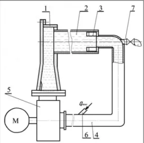
Fig. 1. The design of the vortex cavitator. 1. Vortex chamber with tangential inlet;
2. Resonator body; 3. Tuner straightener; 4. Return pipeline; 5. Power centrifugal pump; 6. The inlet of the transit flow; 7. Outlet of the transit flow
in passive external zones and in internal areas. Technological capabilities making possible the development of other highly efficient technologies also increase the relevance of this area, for example, the creation and applica- tion of magnetorheological fluids, as well as technologies based on changes of water properties with the effect of cavitation. However, existing devices (fluid whistles) only utilize 6–10% of the incoming power for creating output acoustic field; the rest is wasted.
It is advisable to use a cavitator containing a vortex chamber as a liquid whistle, along with and a cylindrical resonator body coaxial with it, one sim- ilar to the Ranke vortex tube, or Potapov’s heat generator (Potapov, 1993).
Elastic oscillations are created in the vortex chamber by operation on liquids, and the amplitude of these oscillations doubles in the resonator body due to the birth of a standing wave in it; this stipulates its higher efficiency com- pared to other cavitator designs (Fig. 1).
However, the doubling of the amplitude of elastic waves is achieved by the means of the high hydraulic resistance of the vortex flow motion in the body in this case. Consequently, this either reduces the vortex component of this flow (Ivanov, 2014) or uses the circumferential component of this flow, for example, in combination with the operational process of the feeding cen- trifugal pump, which produces movement of the working fluid in the cavi- tator.
It ensues from the basic equation of centrifugal machines that when the flow entering the pump swirls against the impeller rotation, the pressure generated by the impeller increases.
Hвстр = H0 + (U1C1U/g)ηΓ kz , (1) swirling it in the same direction with the impeller decreases the pressure
Hпоп = H0 + (U1C1U/g)ηΓ kz , (2) U2 – circumferential velocity of impeller rotation on the external diameter, U1 – circumferential velocity of media rotation on the inlet diameter of the m/s;
impeller, m/s;
С2U – projection of the absolute velocity of operational liquid by exiting from the impeller to the external direction, m/s;
С1U – projection of the absolute velocity of operational liquid by exiting from the impeller to the external direction, m/s;
g – gravitational acceleration, m/s2.
However, the total pressure, or the specific energy of the fluid in the latter case should equal the pressure of the pump operating in the absence of a preliminary swirl, that is, as in the axial input into the pump. This is taking
into account the addition of the energy of the preliminary flow rotation to the energy it got from the pump. This corresponds to the standard technical characteristics of the centrifugal pump.
As the preliminary flow swirl is equal to the rotational frequency of the impeller, the power consumption in the pump by co-directional swirl is sig- nificantly lower than that of the counter-swirl or its absence
Nпоп = N0 [1 – (C1U U1/ C2U U2)]1.5. (3) Therefore, in the case under consideration, it is advisable to install the
vortex chamber with respect to the pump in such a way that it creates a flow swirl at the inlet of the pump impeller that is co-directional to the latter.
Hypothesis: The use of a pre-swirled flow after a vortex chamber at the inlet to a centrifugal pump in the same direction with the impeller rotation should save power consumption without reducing the pressure characteris- tics of the pump.
The results of a priori experimental studies confirm this assumption. So, a swirl, co-directional to the impeller, is preferable from the point of view of smaller energy intensity to the counter- one. It is true for all rotation frequen- cies of the impeller of the feed pump (Fig. 2).
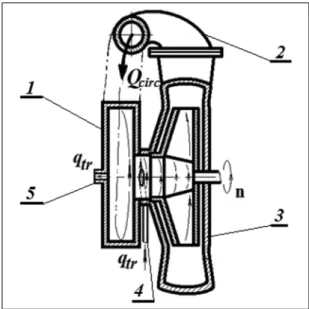
This justifies the assumption (Ivanov et al., Patents RU2669442) that de- signing the body capable of rotation (Fig. 3) should provide a higher value of the rotary component rotrotation > rotinitial by excluding friction between the rotating flow and the inner surface of the body. It will create an even greater effect, in terms of power consumption as in ratio of the net power to the one consumed, and in the pressure characteristics of the pump.
However, the conditions under which the above experiments were car- ried out implied that the flow swirl from the body is preserved solely by ex- Fig. 2. Stand for assessing the effect of transverse swirling of the circulating flow on the en- ergy performance of the pump and its graphical interpretation (the structural elements of the stand in terms of location and configuration correspond to the diagram shown in Fig. 1)
cluding the rectifying device at its outlet. This is, however, clearly insufficient for making reliable conclusions on a long return pipeline, in the condition of its turning 180°.
Consequently, the feasibility of developing a vortex cavitator with a ro- tating body requires additional experimental justification.
Objective of work: Evaluation of the feasibility of using a rotating body in a vortex cavitator with rotation, co-directional to the pump impeller.
Materials and methods
One of the advantages of a vortex cavitator with a rotating body is the pres- ervation of the vortex component of the flow as it passes along the body and is then fed to the impeller blades.
However, such a vortex cavitator is complex and expensive, it requires a long time to accumulate resources, manufacture, and debug. Therefore, to study the feasibility of using it, an analogous equivalent was created in the form of a well-known cavitator (Potapov, 1993), but with a resonator case removed from the device. In this case, in one design, the vortex flow created in the vortex chamber enters through a shortened return pipeline into the impeller of the centrifugal pump (Fig. 4).
Fig. 3. Vortex cavitator with a rotating body and a stationary jacket-casing. 1. Swirl chamber with tangential entry; 2. Resonator case; 3. Tuner straightener; 4. Return pipeline; 5. Power centrifugal pump; 6. The inlet of the transit flow; 7. Outlet of the transit flow; 8. Body rotation supports; 9. Fixed jacket-casing; 10. Technological load;
11. Electric motor of the drive
Fig. 4. The vortex cavitator with the excluded case is the energy analogue of the cavitator with a rotating case (the structural elements of the stand correspond
to the diagram shown in Fig. 5 in terms of location and configuration)
Fig. 5. The structure of the vortex cavitator with coaxial arrangement of the vortex cham- ber and the centrifugal pump. 1. Swirl chamber with tangential inlet; 2. Return pipeline;
3. Power centrifugal pump; 4. The inlet of the transit flow; 5. Outlet of the transit flow
In another design, it enters from the whirl chamber of the cavitator through a short pipe directly into the impeller of the centrifugal pump (Fig. 5).
Thus, hydraulic losses associated with removing a stationary body are avoided and the tangential component of the flow created in the vortex chamber is retained. This approach made it possible to assemble a functional analogue of the vortex cavitator from the available prototype with minimal costs and to get a conclusion on the feasibility of further work on the devel- opment of the concept of vortex cavitators with a rotating body in a short time.
The experimental stand with a cavitator analog functioned as follows:
• the internal operational space of the vortex cavitator was pre-filled with tap water and then the transit flow qtr was put through it;
• electric drive of the vane pump was switched on;
• as the acoustic-cavitation process was stabilizing, the water of the transit flow heated up and this served as a measure of the completeness of the cavitation processes and the effectiveness of the vortex cavitator (taking into account the power consumption).
Variable factors of the experiment are:
q – the amount of transit flow through the vortex cavitator was set by the valve, and was evaluated using the measuring tank and an electronic stopwatch; f – the frequency of the electric current to the electric motor of the drive, which determines the speed of rotation of the pump impeller, was set with the frequency converter “Vesper”;
the vortex chamber swirl direction of the flow, entering the pump, deter- mined by its installation mode, was adjusted by replacing the vortex cham- ber, and response functions were:
∆p – pressure difference at the inlet and outlet of the feed pump [m] was measured by gauges of 1.5 accuracy class;
W – the power consumed by the asynchronous electric drive of the pump [kW] was measured by a three-phase electronic meter “Mercury”;
∆t – temperature difference at the entrance and exit of the transit flow [deg]
was evaluated with a laser pyrometer and an alcohol thermometer with a measurement limit of up to 60°.
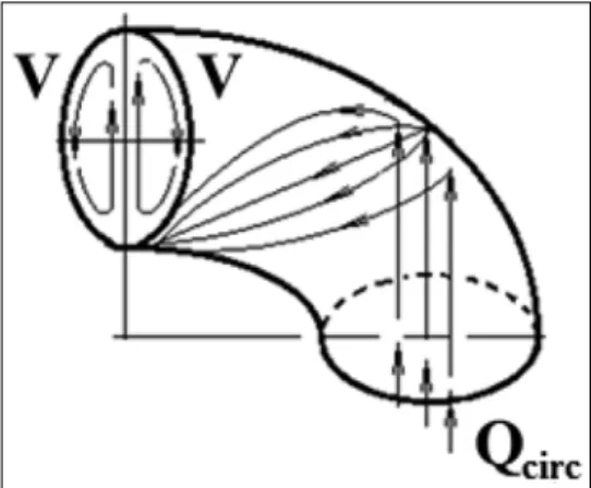
A feature of the structures considered, of both analogs and the model proposed, is the presence of a return pipeline, turning at an angle of 180°, in all of them. This configuration of the flow part implies the creation of two mated vortex longitudinal currents at its initial part by plugging the core of the axisymmetric flow into the peripheral inner part of the beginning of the turn, its subsequent spreading over the inner torus surface to smaller radii and further closing with multiple repetition of these cycles (Fig. 6).
Being superimposed on a spiral monovortex flow coming out of the vortex chamber, these currents deform it. For this reason, a non-stationary polyvortex structure appears at the pump inlet. It does not contribute to the manifestation of the fully-predictable interaction of the rotating blades with the co-directional input flow. This is especially relevant for the design pro- posed (Fig. 3), and for its energy equivalent with the excluded body (Fig. 4), since all measures to eliminate the two-vortex flow are equally fatal for a specially created monovortex one. The only measure to eliminate it is to bring the outlet of the vortex chamber as close as possible to the pump inlet (Fig. 5).
In the proposed design (Fig. 3), this is achieved by the sequential connection of several cavitators.
Therefore, the second stage of research was also carried out on a physical model in which the central outlet of the vortex chamber is coaxially connect- ed to the inlet of the centrifugal pump through a short cylindrical pipe, and the pressure pipe of the pump is connected to the inlet tangential pipe of the vortex chamber with torus pipeline (Fig. 5).
In such a connection of the vortex chamber with the pump, the mon- ovortex flow emerging from it gets directly into the central neck of the im- peller and interacts with its blades without being subjected to external in- fluences.
Results
The results of experimental studies of two builds of vortex cavitators:
• the classic full version – “full” (Fig. 1);
• experimental build of the vortex cavitator with coaxial arrangement of the vortex chamber and centrifugal pump – “exp” (Fig. 5); presented in Table 1.
Fig. 6. The mechanism of formation of two mated torus vortices in the outlet
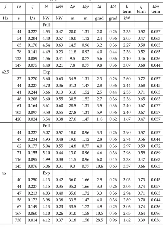
Table 1. Energy parameters of comparable vortex cavitators
f τ q q N ±δN ∆p ±δp ∆t ±δt E
term η
term ±δη term
Hz s l/s kW kW m m grad grad kW
42.5
Full
44 0.227 4.53 0.47 20.0 1.31 2.0 0.26 2.35 0.52 0.057 54 0.204 4.40 0.57 18.0 1.12 2.4 0.36 2.05 0.47 0.063 65 0.170 4.54 0.63 14.5 0.96 3.2 0.36 2.27 0.50 0.063 78 0.141 4.49 0.23 11.8 0.92 4.0 0.44 2.36 0.52 0.085 123 0.089 4.56 0.41 9.5 0.77 5.6 0.36 2.10 0.46 0.036 147 0.075 4.48 0.21 7.8 0.77 9.8 0.36 3.07 0.68 0.044
Exp
37 0.270 3.60 0.63 34.5 1.31 2.3 0.26 2.60 0.72 0.057 44 0.227 3.70 0.36 31.3 1.47 2.8 0.36 2.44 0.68 0.045 41 0.244 3.66 0.13 31.0 1.52 2.5 0.44 2.55 0.71 0.063 48 0.208 3.60 0.55 30.5 1.52 2.7 0.36 2.36 0.65 0.063 61 0.164 3.61 0.60 28.5 1.31 3.5 0.36 2.40 0.67 0.077 103 0.097 3.58 0.55 27.8 1.31 5.9 0.36 2.40 0.67 0.057 420 0.024 3.54 0.38 27.0 1.47 1..8 0.62 1.67 0.47 0.057
45
Full
44 0.227 5.07 0.57 18.0 0.96 3.3 0.26 2.90 0.57 0.057 47 0.234 4.93 0.48 19.0 1.12 2.8 0.36 2.74 0.56 0.044 62 0.177 5.04 0.55 14.8 0.77 4.0 0.36 2.97 0.59 0.072 71 0.155 5.10 0.44 13.0 0.96 4.6 0.36 2.98 0.59 0.089 116 0.095 4.99 0.38 11.5 0.96 6.0 0.45 2.38 0.47 0.063 145 0.076 5.06 0.31 9.3 0.77 10.6 0.63 3.37 0.66 0.063
Exp
40 0.250 4.13 0.42 36.0 1.66 2.9 0.26 3.03 0.73 0.045 44 0.227 4.15 0.35 35.2 1.66 3.3 0.26 3.06 0.74 0.057 47 0.213 4.03 0.40 35.0 1.72 3.3 0.36 2.94 0.71 0.063 58 0.172 3.98 0.38 33.5 1.47 4.0 0.36 2.89 0.70 0.044 67 0.149 4.13 0.23 33.5 1.72 4.9 0.25 3.06 0.74 0.036 167 0.060 4.10 0.26 31.0 1.58 10.5 0.36 2.63 0.64 0.096 738 0.014 4.12 0.37 31.8 1.58 28.5 0.96 1.62 0.39 0.036
47.5
155 0.071 5.62 0.35 10.8 0.96 7.6 0.45 2.26 0.40 0.044 171 0.064 5.59 0.19 8.0 0.77 13.2 0.36 3.56 0.63 0.072
Exp
39 0.256 4.78 0.49 41.5 1.58 3.4 0.26 3.65 0.76 0.063 44 0.227 4.80 0.76 40.8 1.83 3.7 0.36 3.52 0.73 0.072 48 0.208 4.83 0.40 39.3 1.73 4.0 0.36 3.49 0.73 0.057 58 0.172 4.76 0.42 38.1 1.52 5.0 0.26 3.61 0.75 0.063 70 0.143 4.82 0.22 37.8 1.64 6.2 0.36 3.71 0.77 0.057 87 0.115 4.80 0.69 37.0 1.80 6.9 0.57 3.32 0.69 0.077 159 0.063 4.81 0.28 35.2 1.58 11.6 0.44 3.05 0.64 0.063
50
Full
44 0.227 6.53 0.48 19.5 1.31 3.5 0.36 3.46 0.53 0.057 56 0.196 6.67 0.51 18.3 1.12 4.0 0.26 3.29 0.49 0.063 70 0.157 6.53 0.30 15.5 1.18 5.4 0.57 3.55 0.54 0.044 86 0.128 6.55 0.58 13.3 1.06 8.0 0.26 4.28 0.66 0.112 138 0.080 6.65 0.25 11.8 0.96 9.0 0.36 3.00 0.46 0.077 169 0.065 6.55 0.45 9.0 0.85 13.0 0.77 3.54 0.54 0.063
Exp
38 0.263 5.45 0.16 44.8 1.87 3.9 0.45 4.30 0.79 0.077 44 0.227 5.47 0.19 44.1 1.67 4.4 0.36 4.05 0.74 0.057 53 0.189 5.49 0.30 44.0 1.92 4.9 0.26 3.87 0.71 0.063 55 0.182 5.51 0.16 41.8 1.72 5.6 0.26 4.26 0.78 0.044 70 0.143 5.43 0.56 40.8 1.72 6.6 0.45 3.95 0.72 0.077 88 0.114 5.47 0.15 40.2 1.69 8.1 0.26 3.85 0.70 0.118 335 0.030 5.44 0.58 39.0 1.72 25.6 0.45 3.20 0.59 0.096
f τ q q N ±δN ∆p ±δp ∆t ±δt E
term η
term ±δη term
Hz s l/s kW kW m m grad grad kW
52.5
Full
44 0.227 8.01 0.64 21.0 1.67 3.0 0.36 3.60 0.45 0.036 58 0.190 7.87 0.53 18.2 1.52 4.0 0.25 3.18 0.40 0.096 70 0.157 7.89 0.54 16.5 1.12 5.2 0.44 3.42 0.43 0.072 85 0.129 7.93 0.49 14.0 1.18 6.0 0.26 3.25 0.41 0.126 136 0.081 7.97 0.31 11.8 0.96 9.4 0.36 3.18 0.40 0.044 161 0.068 8.04 0.51 9.8 0.85 13.0 0.77 3.72 0.46 0.117 173 0.064 8.01 0.38 9.0 0.85 18.2 0.57 4.84 0.61 0.117
Exp
40 0.250 6.13 0.38 49.0 2.01 4.5 0.26 4.71 0.77 0.077 44 0.227 6.27 0.51 48.5 1.66 5.0 0.44 4.63 0.74 0.112 50 0.200 6.23 0.44 48.5 1.72 5.4 0.36 4.52 0.72 0.131 54 0.185 6.26 0.35 46.8 1.82 6.0 0.63 4.65 0.74 0.092 63 0.159 6.27 0.30 45.5 1.72 7.2 0.36 4.78 0.76 0.077 79 0.127 6.40 0.28 45.3 1.88 8.7 0.36 4.61 0.72 0.112 150 0.067 6.31 0.39 44.2 1.80 14.5 0.63 4.05 0.65 0.118 300 0.033 6.32 0.25 43.5 1.88 31.7 0.96 4.42 0.71 0.057
55
Full
44 0.227 8.67 0.51 23.5 1.64 2.5 0.26 3.55 0.41 0.026 60 0.183 8.64 0.35 19.2 1.12 3.8 0.36 2.92 0.34 0.085 70 0.157 8.80 0.26 16.5 1.18 4.8 0.45 3.16 0.36 0.096 90 0.122 8.69 0.44 13.0 0.96 6.6 0.36 3.38 0.39 0.118 126 0.087 8.77 0.51 11.5 0.96 9.6 0.45 3.51 0.41 0.072 164 0.067 8.76 0.60 9.8 0.77 13.6 0.26 3.82 0.44 0.044 193 0.057 8.78 0.63 9.0 0.77 19.2 0.26 4.58 0.53 0.154
Exp
43 0.233 7.07 0.53 54.0 2.07 5.6 0.26 5.45 0.77 0.077 44 0.227 7.20 0.64 53.0 1.58 5.6 0.36 4.97 0.69 0.077 49 0.204 7.22 0.35 53.0 1.58 6.2 0.44 5.30 0.74 0.112 58 0.172 7.12 0.10 53.0 1.8 6.6 0.26 4.76 0.66 0.112 64 0.156 7.18 0.36 50.0 2.02 7.8 0.26 5.10 0.71 0.077
Table 1. (cont’d)
57.5
57 0.193 9.56 0.28 21.3 0.63 3.8 0.26 3.07 0.32 0.044 70 0.157 9.47 0.52 18.8 1.31 5.8 0.26 3.82 0.40 0.096 90 0.122 9.57 0.52 15.0 0.96 7.6 0.36 3.90 0.41 0.125 158 0.070 9.63 0.60 12.8 1.58 13.4 0.26 3.91 0.41 0.072 194 0.057 9.62 0.42 10.0 0.96 26.0 0.77 6.17 0.64 0.063
Exp
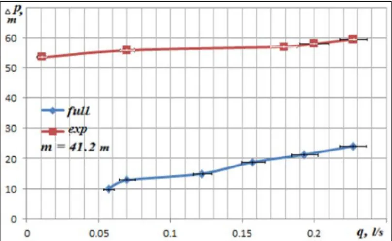
44 0.227 7.87 0.23 59.5 1.58 6.6 0.45 6.28 0.80 0.077 50 0.200 7.83 0.19 58.0 2.38 7.0 0.36 5.86 0.75 0.096 56 0.179 7.91 0.16 57.0 2.20 8.0 0.45 5.98 0.76 0.077 143 0.070 7.85 0.25 55.8 2.44 30.0 0.96 9.66 0.93 0.077 870 0.011 7.92 0.46 53.5 1.48 60.0 1.12 2.89 0.37 0.063 Processing the results of experiments demonstrated that the difference in pressure at the pump inlet and outlet (or the main component of the pump pressure) for the “vortex chamber – pump” design is several times higher than the initial design at low flow rates and on large q in a smaller proportion (60%) (Fig. 7).
The measurement error of transit flow in the above relations is the sum of the errors in measuring the volume of incoming fluid and the time interval for filling this volume. The absolute value of the error in the volume of liquid in the measuring tank is
∆w = ∆ h·S, (4)
where S is the area of the base of the measuring cylinder (it is constant), ∆h is the error in measuring the height of a cylindrical volume filled with liquid. Its value is assumed to be ∆h = 2 mm, which, at a height of h = 252 mm, will determine the relative error w = 0.8%.
The error in measuring time interval during which the measuring tank is filled is determined by the degree of the psychological reaction of the experi- menter on the basis of a priori procedures and is ∆t = 0.5 s. This value makes
it possible to determine the value of relative error by the shortest filling time tmin = 37 s as equal to ηt = 0.5/37 = 1.35%. Consequently, the largest total value of the relative error will be 2.2%, that is, it does not exceed 5%.
Fig. 7. The relation of the pressure difference at the pump to the transit flow rate for the classical build (full) of the vortex cavitator and its proposed version with a rotating case
(exp) for the current frequency f = 57.5 Hz, the measurement error does not exceed 5%
Fig. 8. The relation of the pressure difference at the pump to the frequency of the drive electric current for the classic build (full) of the vortex cavitator and its proposed analog
(exp) with a rotating body (q = 0.227 l/s)
pling n = 3
X ± (tγ /√¯n ) S (5)
at significance levels γ = 0,95 (tγ = 0,315) of each of the compared relations by the means of sequential calculation of dispersion D, effective dispersion S2 = [n/(n – 1)]D and the confidence interval (5).
At the same time, the increase in the pressure difference at the pump by the impeller rotation frequency factor exceeds the pattern corresponding to the similarity theory (dashed line in Fig. 8), therefore, in this case there is an additional process of energy conversion. One of the reasons for the excess pressure in the experimental build as compared to the build with a complete set with stationary case is the drive’s induction motor slip reduction due to the decrease of torque on the shaft from the co-directionally pre-swirled inlet flow. This increases the frequency of rotation of the drive shaft, and hence
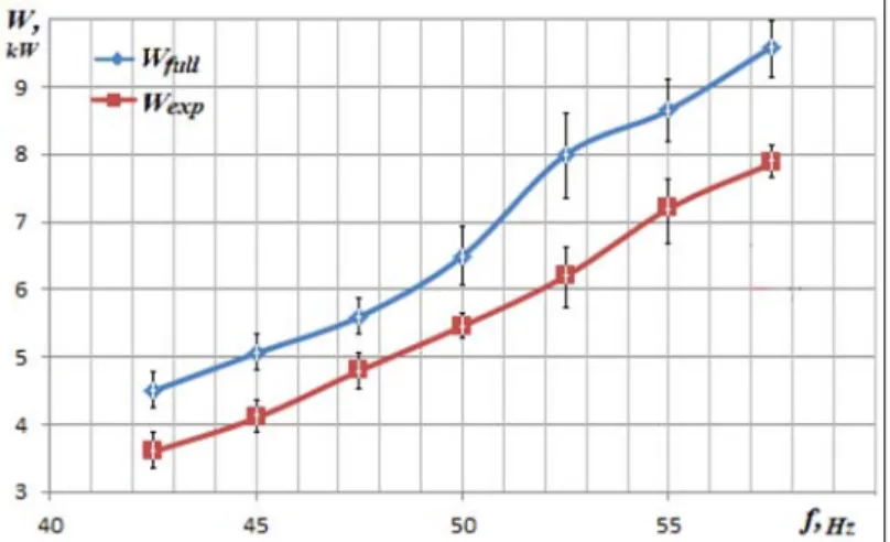
Fig. 9. The power consumption related to the frequency of the current of the electric drive for the compared builds of vortex cavitators (q = 0.227 l/s)
the impeller of the vane pump, which ultimately leads to an increase in the pressure difference at the pump, and hence the pump head itself.
The input power for the proposed build of the vortex cavitator with the direct connection of the vortex chamber with the throat of the centrifugal pump suction inlet greatly benefits compared to the original build in terms of savings (Fig. 9).
However, the power reduction in this case reaches only 30% compared to 60% for the pressure difference (Fig. 8), which is caused by the need for ex- tra power use to create an additional excess pressure difference at the pump.
In addition, in this case, the proportions of the power increase are under- estimated by the similarity theory in terms of the rotational speed argument.
This further confirms that in this case there is a power saving. Moreover, in all cases considered, the amount of power does not depend on the transit flow.
Water heating in the vortex cavitator, as a measure of the cavitation pro- cesses flow completeness, occurs more efficiently on the the vortex cavita- tor with a rotating case simulating analog (with a coaxial pump and vortex chamber), since in this case the excess pressure at the outlet of the pump
Fig. 10. Calorific capability related to the frequency of the current of the electric drive for the compared builds of vortex cavitators and evaluation of its difference (qtr = 0.2272 l/s)
considered above converts the device to a higher energy level. This excess in calorific capability ∆t takes place at almost all rotational frequencies (Fig. 10).
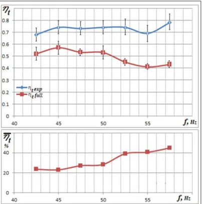
As a result of the above circumstances, the thermal efficiency also has a higher significance, since an increased pump pressure causes a higher circu- lating flow velocity, and therefore a greater amplitude of sound oscillations (Fig. 11). As a result, the dimensions of cavitation caverns increase, the level of elastic energy accumulated in them increases, the energy density by the collapse of these cavitation caverns increases significantly, and all processes associated with collapse are significantly activated.
For the cases of Fig. 7, Fig. 8, Fig. 10 and Fig.11 this indicates that the experimental values are not less than the initial ones, which indicates clear advantages of the experimental build.
For the case corresponding to Fig. 9, m is negative, indicating a lower power consumption of the experimental build.
In Fig. 10 and Fig. 11 the lower part, relative estimates of the compared values differences by the frequency of the alternating current of the electric motor are given, expressed as a percentage.
Fig. 11. Calorific efficiency related to the frequency of the current of the electric drive for the compared builds of vortex cavitators and evaluation of its difference (qtr = 0.2272 l/s)
Discussion
The co-directional swirl of the circulation flow from the vortex chamber to the suction zone of a centrifugal pump allows to adapt the operation of a cen- trifugal pump to the specifics of the vortex chamber functioning, resulting in a significant 30% (or rather, proportional to the vortex component) reduced power consumption of the unit.
This is also true for a build with a rotating body, and, in this case, the preliminary twist can be adjusted, either to increase (by decelerating the case) or decrease, by means of an additional drive for forced rotation of the case (Ivanov et al., Patents RU2669442). We expect that this will further increase the cost-effectiveness and efficiency of the vortex cavitator workflow. In this case, a slight additional power cost can enhance the effect discussed, that is, it is possible to obtain even greater efficiency of the vortex cavitator operation.
This fact remained unknown until now and has not been used, therefore, it has a novelty. On October 11, 2018, the Federal Institute of Industrial Prop- erty of the Russian Federation awarded it an invention certificate No. 2 669 442 “Vortex Cavitator” (Ivanov et al., Patents RU2669442).
Vortex chambers or liquid whistles have been studied significantly since these devices are also used as basis for designing vortex cavitators (Akhmetov et al., 2016; Akhmetov et al., 2018), as vortex chamber sediment extractors (Athar, 2018), and as part of separating devices – hydrocyclones, etc. In addition, by operation on gas, vortex chambers are capable of creating two different temperature vortex flows inside themselves – hot peripheral and cooled central (Matsuo et al., 2015a). Since the devices under consid- eration have been in operation for several decades, many works have been devoted to them, especially in the 1960–80s. As the cavitation technologies develop, new works keep appearing, both on the subject of current structure in them (Matsuno et al., 2015b) and on their separating ability. However, the mechanism of creating sound waves in vortex chambers is not sufficiently studied in the published works, and those existing do not present a unani- mous opinion on the process of creating acoustic cavitation, and the structure of currents itself. For example, Rafiee, Sadeghiazad (2016) indicates that the central return Rossby flow in the vortex tube has a counter swirl to the pe- ripheral vortex flow, and this is not true.
Recent works also do not present results on the use of tangential swirl- ing at the inlet to the vane pump (in cases such swirling takes place) of cen- trifugal pumps for the creation of circulation flows (Jang Jeong Cheol et al., patents KR101869827 (B1)), as well as on their use as supplying ones (Blad, patents WO2018166975 (A1)).
Moreover, due to the reduction of torque on the impeller shaft, the fa- vorable combination of functions of the vortex chamber and the centrifugal pump extends to the third link of the unit – an asynchronous electric motor.
characteristics of the centrifugal pump (and hence the pressure difference on the pump inlet and outlet), which requires a part of the saved power, so its reduction is less observable.
The growth of the units’ pressure parameters leads to an increase of 20–45% in the completeness of the cavitation processes flow (Fig. 11), which indicates the feasibility of the build considered.
Reducing energy consumption while improving the technological per- formance of acoustic-cavitation processes will expand the boundaries of the application of such technologies, will speed known processes with liquid me- dia already known, and make possible the occurrence of many previously impossible.
It is remarkable that the proposed design version of the vortex cavitator with the necessary modifications is a technical novelty.
The operating modes of the centrifugal pump Qcentrifugal must be consid- ered because its most effective value matches to only a certain narrow range
∆Qopt corresponding to the highest values of the pump efficiency function at Qcentrifugal (η = f (Qcr)). For this reason, experiments included various frequen- cies of the electric current f = 40–60 Hz (or impeller rotation n ≈ 35–55 1/s), which ensured the displacement of the pump operating point by the criterion of relative flow and allowed to capture the optimal mode Qopt of the pump with all combinations of variable factors.
This work experimentally confirms the calculated reduction in power consumption and no decrease in the pressure characteristics of a centrifugal pump with co-directional swirl of the inlet flow, as well as augmentation of this effect with increasing intensity of the swirling.
The results showed the validity of the proposed hypothesis and the fea- sibility of further work on the creation of a vortex cavitator with a rotating body.
Conclusions
Analysis results of experiments established the feasibility of designing the vortex cavitator with rotating body, which will provide power saving of at
least 30% by its co-directional rotation with the impeller, as well as a 55% in- crease in pressure at the pump outlet. The latter will improve the quality and efficiency of the vortex cavitator operation.
We observed the effect of co-directional pre-swirl at the centrifugal pump inlet on the drive induction motor operation, causing a decrease in the slip in it and an increase in the rotational speed of its rotor, thanks to the lat- ter. This increases in the pressure characteristics of a centrifugal pump more (by 2–3 m) than can be achieved by co-directional pre-swirl alone.
The growth of the pressure difference at the inlet and outlet of the cen- trifugal pump (pressure parameters) in combination with other factors pro- duces an increase of 20–40% of the device’s cavitation capabilities and its efficiency.
The study demonstrates a potential for achieving even higher vortex cavitator performance by the forced rotation of its body.
The study demonstrates a method for increasing the efficiency of the centrifugal pump operation using the energy of the pre-swirl by co-direction- al swirl of the input flow.
Since the use of cavitation technologies increases productivity and qual- ity of many technological processes as compared to the conventional ones, by improving the functional parameters of the vortex cavitator the efficiency of such processes can be further enhanced and the scope of application wid- ened, which will in turn determine the further development of these technol- ogies.
The promising development vector for devices of the considered physi- cal action principle is established.
References
Akhmetov, D. G., Akhmetov, T. D. (2016) Flow structure in a vortex chamber. Journal of Applied Mechanics and Technical Physics 57(5): 879–887.
Akhmetov, D. G., Akhmetov, T. D., Pavlov, V. A. (2018) Flow Structure in a Ranque-Hilsch Vortex Tube. Doklady Physics 63(6): 235–238.
Athar, M., Srotriya, S. (2018) Velocity Distribution in Vortex Chamber at High Water Ab- straction Ratio. Hydrologic Modeling. Water Science and Technology Library, Vol. 81.
Springer, Singapore, pp. 459–473.
Bagal, M. V., Gogate, P. R. (2014) Wastewater treatment using hybrid treatment schemes based on cavitation and Fenton chemistry: A review. Ultrasonics Sonochemistry 21(1):
1–14.
Blad, Th. Pump assembly, patents WO2018166975 (A1), 2018-9-20, F04D1/00; F04D13/06;
F04D15/00; F04D29/42; F04D29/48; F24D3/10.
Favrel, A., Gomes, J., Junior, P., Landry, Ch., Müller, A., Yamaishi, K., Avellan, F. (2018) Dynamic modal analysis during reduced scale model tests of hydraulic turbines for hydro-acoustic characterization of cavitation flows. Mechanical Systems and Signal Processing 117: 81–96.
Potapov U. S. Heat generator and device for heating liquids. Patents RU2045715, 1993-04- 26, F25B29/00.
Jung Chul Min, Kim Chan Ki, Park Warn Gyu, Cavitation Device of Under Water Moving Body and Under Water Moving Body Having the Same, patents US2013298819 (A1) – 2013-11-14, B63B1/36; B63G8/00.
Karn, A., Arndt, R. E. A., Hong, J. (2016) An experimental investigation into supercavity closure mechanisms. Journal of Fluid Mechanics 789: 259–284.
Li Fuyuan, Li Guozhong, Ma Zengshuai, Zhao Hailong, Resistance self-adaptive variable structural cavitator, patents CN107310687 (A) – 2017-11-03, B63B1/38.
Matsuno, Y., Fukushima, Y., Matsuo, Sh., Hashimoto, T., Setoguchi, T., Kim, H. D. (2015) Investigation on temperature separation and flow behavior in fortex chamber. Jour- nal of Thermal Science 24(2): 149–154.
Matsuo, Sh., Matsuno, Y., Fukushima, Y., Mamun, M., Hashimoto, T., Setoguchi, T., Kim, H. D. (2015) Experimental Study on Temperature Separation in Vortex Chamber.
Procedia Engineering 105: 464–471.
Qiu, S., Ma, X., Huang, B., Li, D., Wang, G., Zhang, M. (2018) Numerical simulation of single bubble dynamics under acoustic standing waves. Ultrasonics Sonochemistry 49:
196–205.
Rafiee, S. E., Sadeghiazad, M. M. (2016) Three-dimensional CFD simulation of fluid flow inside a vortex tube on basis of an experimental model – The optimization of vor- tex chamber radius. International Journal of Heat and Technology 34(2): 236–244. DOI:
10.18280/ijht.340212.
Sivakumar, M., Tang, S. Y., Tan, Kh. W. (2014) Cavitation technology – A greener pro- cessing technique for the generation of pharmaceutical nanoemulsions. Ultrasonics Sonochemistry 21(6): 2069–2083.
Vignjevic Rade [GB]. Cavitation Generation, patents WO2015001315 (A2) – 2015-01-08, B65B1/24.
Wu, P., Bai, L., Lin, W., Wang, X. (2018) Mechanism and dynamics of hydrodynam- ic-acoustic cavitation (HAC). Ultrasonics Sonochemistry 49: 89–96.