Journal Pre-proof
Simplification of the CCVD method used in the growth of carbon nanotube forests on titanium substrate
Anna Szabó, Lilla Nánai, Zsejke Réka Tóth, Klara Hernadi
PII: S1293-2558(21)00116-3
DOI: https://doi.org/10.1016/j.solidstatesciences.2021.106648 Reference: SSSCIE 106648
To appear in: Solid State Sciences Received Date: 9 April 2021
Revised Date: 10 May 2021 Accepted Date: 10 May 2021
Please cite this article as: A. Szabó, L. Nánai, Z.R. Tóth, K. Hernadi, Simplification of the CCVD method used in the growth of carbon nanotube forests on titanium substrate, Solid State Sciences, https://
doi.org/10.1016/j.solidstatesciences.2021.106648.
This is a PDF file of an article that has undergone enhancements after acceptance, such as the addition of a cover page and metadata, and formatting for readability, but it is not yet the definitive version of record. This version will undergo additional copyediting, typesetting and review before it is published in its final form, but we are providing this version to give early visibility of the article. Please note that, during the production process, errors may be discovered which could affect the content, and all legal disclaimers that apply to the journal pertain.
© 2021 The Author(s). Published by Elsevier Masson SAS.
Simplification of the CCVD method used in the growth of carbon nanotube forests on titanium substrate
Anna Szabóa, Lilla Nánaia, Zsejke Réka Tótha,b, Klara Hernadia,c1
aDepartment of Applied and Environmental Chemistry, University of Szeged, H-6720 Szeged, Rerrich Béla tér 1, Hungary
bNanostructured Materials and Bio-Nano-Interfaces Center, Institute for Interdisciplinary Research on Bio-Nano-Sciences, Babeș-Bolyai University, Treboniu Laurian 42, RO-400271, Cluj-Napoca, Romania
cInstitute of Physical Metallurgy, Metal Forming and Nanotechnology, University of Miskolc, 3515 Miskolc-Egyetemváros, Hungary;
CRediT author statement
Anna Szabó: Conceptualization, Visualization, Investigation, Writing- Original draft preparation, Formal analysis
Lilla Nánai: Investigation, Visualization, Data curation
Zsejke Réka Tóth: Investigation, Formal analysis, Sofware
Klara Hernadi: Writing- Reviewing and Editing, Supervision, Resources
1 Corresponding author: hernadi@chem.u-szeged.hu
Journal Pre-proof
Journal Pre-proof
Simplification of the CCVD method used in the growth of carbon nanotube forests on titanium substrate
Anna Szabóa, Lilla Nánaia, Zsejke Réka Tótha,b, Klara Hernadia,c*
aDepartment of Applied and Environmental Chemistry, University of Szeged, H-6720 Szeged, Rerrich Béla tér 1, Hungary
bNanostructured Materials and Bio-Nano-Interfaces Center, Institute for Interdisciplinary Research on Bio-Nano-Sciences, Babeș-Bolyai University, Treboniu Laurian 42, RO-400271,
Cluj-Napoca, Romania
cInstitute of Physical Metallurgy, Metal Forming and Nanotechnology, University of Miskolc, 3515 Miskolc-Egyetemváros, Hungary;
Abstract
The carbon nanotubes (CNTs) play an important role in nanotechnology research today as they have the potential to be used in several areas. Environmental protection is highly discussed nowadays, which is why it is necessary to be able to produce CNT forests with less energy investment and simply, for these reasons we used the dip-coating layer construction method, which is a simple process. We also would like to simplify the production of CNT forests by changing several parameters used in the syntheses (concentration of ink, catalyst ratios, temperature, the effect of heat-treatment, hydrogen, and water vapor, reaction time, carbon source). For these reasons, this research uses a dip-coating method to form a catalyst layer on the surface of the substrate, as well as to investigate various parameters to produce CNT forests directly on the titanium substrate, as it is important today to use a conductive substrate.
Keywords
Carbon nanotubes, Catalytic chemical vapor deposition, Titanium substrate, Dip-coating, Synthesis parameters
* Corresponding author: hernadi@chem.u-szeged.hu
Journal Pre-proof
1. Introduction
The carbon nanotubes (CNT) are used in many fields today due to their outstanding properties. One form of CNTs is 3D-structured vertically aligned carbon nanotubes, which have unique electrochemical properties, so the CNT forests can be used in a wide range of applications such as gas sensors, chemical sensors, transistors, and supercapacitors [1–4].
Such structure was first produced in 1996 by a Beijing research group using catalytic chemical vapor deposition (CCVD) synthesis [5]. Nowadays, it is important to produce CNT forests on a conductive substrate, so aluminum, copper, stainless steel and titanium substrates are often used [6–10]. In addition, it is possible to form a catalyst layer on the substrate surface with several layer building methods such as spin-coating, spray-coating, pulsed laser deposition (PLD), and dip-coating [11–14]. However, it is increasingly important to use simple methods to make this structure more cost-effective; according to the literature, the dip- coating process has already been applied to nickel substrate for catalyst film deposition and then CNT forest has been successfully grown on the substrate [15]. The dip-coting method is already used in industry as well to form paint layers on the surface.
An insulating oxide support layer is often used in the literature for the production of CNT forests, most commonly alumina oxide [16]. However, if it is possible to form the oxide support layer by heat treatment, the synthesis can be further simplified. Moreover, in certain cases the direct growth of CNT forests on the substrate is fully possible without the oxide support layer [17], which requires better catalyst adhesion for many substrates, thus simplifying the synthesis, so CNT forest fabrication is possible in fewer steps. Several parameters influence the growth of CNT such as hydrogen, temperature, reaction time [18–
20] during the production of CNT forests. CNT forests could be produced at lower temperatures, which could involve less energy investment. CCVD syntheses of CNT forests require a reduction step, often using hydrogen [21], however, if hydrogen were present in the system only for a short period to reduce catalyst particles, the synthesis could be made safer.
Nowadays, environmental protection is an important factor, and for these reasons, natural carbon compounds have been used as carbon source in the growth of CNT forests in the literature [22–24], which can exclude the frequently used ethylene or acetylene [25], which could make the production of CNT forests more environmentally benign.
In this research, for the reasons mentioned above, we aimed to synthesize CNT forests as simple as possible. Any reducibility of the CCVD process could enhance the application of
Journal Pre-proof
the product. Former studies revealed [4] that among conductive substrates titanium provided the best performance, therefore this material was chosen for further experiments. However, all parameters are interactant, so a systematic study was carried out for further development.
For building catalyst layer, the common dip-coating method was used. Then, we investigated whether it was possible to achieve the CNT forest structure directly on the titanium substrate without using a supporting oxide layer. In addition, it was important to determine how the parameters used in the syntheses (concentration of ink, catalyst ratios, temperature, heat- treatment for substrate, hydrogen, water vapor, reaction time, carbon source) affect the growth of CNT forests and in order to exclude unnecessary parameters. In consequence, it is possible to achieve and control the CNT forest structure via making the syntheses easier.
2. Experimental 2.1. Materials
Titanium substrate (99%, VWR) as conductive substrate was used in the syntheses, and iron- and cobalt-nitrate (iron(III) nitrate nonahydrate, 99.9%, Sigma-Aldrich; cobalt(II) nitrate hexahydrate, 99%, Sigma-Aldrich) in various ratios and concentrations dissolved in absolute ethanol (99.8%, VWR) were used as catalyst precursors in the dip-coating method.
In some cases, the aluminum-nitrate (aluminum-nitrate nonahydrate, 98%, Sigma-Aldrich) was used as support layer on the substrate. During the syntheses, various carbon compounds were used, which were acetone (Ac; a.r., Molar Chemicals Kft.), absolute ethanol (99.8%, VWR), palinka (homemade Hungarian brandy), cyclohexane (a.r., Molar Chemicals Kft.), diethyl ether (≥99%, VWR) and ethyl acetate (99.5 %, Molar Chemicals Kft.). In the syntheses of the samples, the carrier gas was nitrogen (99.995%, Messer), the reducing agent was hydrogen (99.5%, Messer), and the carbon source was ethylene in general (>99.9%, Messer). In some experiments carbon source different than ethylene was also used to prove the applicability of other C-containing compounds.
2.2. Catalyst preparation
The catalyst layer on the substrate was formed by a simple method, which was the dip-coating. First, the surface of the substrate was cleaned with ethanol, acetone, and distilled water to confirm uniform adhesion of the catalyst layer. Then, the catalyst ink was prepared by using iron- and cobalt-nitrate, which were mixed in absolute ethanol, working with
Journal Pre-proof
different catalyst ratios and concentrations during the syntheses. However, the most common concentration was 0.11 M, while the catalyst ratio was Fe:Co = 2:3. The catalyst layer formation was then performed, and the samples were heat-treated at 400 °C for 1 h in a static oven to stabilize the catalyst layer on the surface of the substrate.
2.3. CCVD synthesis
The next step was the synthesis of the CNT forests, where in the first case, the substrates containing the catalyst layer were cut to size of 4×4 mm. The cut-to-size substrate was placed in a quartz reactor and the reaction was subjected to a nitrogen purge to displace the oxygen in the system. In the next step, the reactor was placed in a preheated furnace (700
°C). Afterwards, the hydrogen gas was introduced into the reactor, which reduced the catalyst particles in 5 minutes. Then, in addition to hydrogen, the feed of carbon source and water vapor was started. At the end of the synthesis time, which was 30 minutes, all gases were turn off except nitrogen, and after the quartz tube was cooled down to room temperature, the sample was taken from the reactor and further analyses were performed. The gas flow rates were 80 cm3/min for hydrogen, 70 cm3/min for ethylene, 45 cm3/min for water vapor, and 40 cm3/min for nitrogen. The parameters of the synthesis changed during the study of the various effects, which were described in the results part, but the general synthesis was the same as that described in their section. In order to gain information about the formation of catalytic particles from the homogeneous layer, so-called blank synthesis was carried out.
During which all steps were identical except for the feed of carbon source and water vapor.
2.4. Characterization of CNT samples
The CNT forests were examined by a Hitachi S-4700 Type II FESEM (5–15 keV) scanning electron microscope (SEM) to obtain information on their structure. For clear presentation of SEM images of CNT forests, they were organized into tables in the relevant sections and also framed by either green or red color. The coding is the following: samples with green frame seemed to be worth for further investigation, while with the red-marked samples we did not continue experiments. In addition, transmission electron microscope (TEM) measurements were performed by a FEI Tecnai G2 20 X-TWIN (200 keV) type machine to determine the diameter of CNTs. Raman spectroscopic measurements were also
Journal Pre-proof
performed by a Thermo Scientific DXR Raman microscope (excitation wavelength 532 nm) to collect information on the graphitization of the CNT forests.
3. Results and discussion
Describing the results, first we present the effect of parameters during the building of catalyst layer, which is the first step in the production of CNT forest. Then the effect of parameters used in the CCVD synthesis is demonstrated, according to which the effect of temperature, reaction time, hydrogen, water vapor, and different carbon sources was studied.
3.1. Effect of heat-treatment applied during catalyst layer construction on the growth of CNT forests
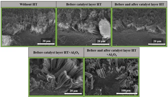
During the syntheses, in some cases heat-treatment was performed on the substrate to observe whether a native oxide layer formed on the surface of the substrate during heat- treatment which might have a crucial role in achieving the desired structure. In order to investigate whether it is possible to produce CNT directly on the substrate without a support oxide layer different layers were built [26]. For comparison, alumina layer was also built on the substrate to investigate how these parameters affect the growth of CNT forests, as some oxide layer between the catalyst layer and the substrate was often used in the literature for better adhesion [17]. To clarify all possible effects, catalyst layer was prepared without any heat treatment (reference sample), with or without alumina layer, and heat treatment at 400
°C before and after dip-coating. SEM images were taken of as-grown carbon deposits, which
are shown in Fig. 1.
Journal Pre-proof
Fig. 1: SEM images of CNT forests synthesized over substrates with different heat- treatments (HT) applied during catalyst layer building.
The samples h (µm) ID/IG diameter of CNT (nm)
diameter of catalyst particle (nm) Without HT 11.1 ± 2.6 1.0 14.1 ± 4.6 31.5 ± 7.2 Before catalyst layer HT 7.2 ± 1.5 1.0 4.7 ± 2.0 55.2 ± 17.1 Before and after catalyst
layer HT 8.0 ± 1.2 1.1 10.4 ± 4.2 79.7 ± 31.3 Before catalyst layer
HT+Al2O3 26.2 ± 4.3 1.1 7.2 ± 3.5 49.2 ± 22.6 Before and after catalyst
layer HT +Al2O3 56.5 ± 12.3 1.2 9.2 ± 4.8 40.6 ± 11.2 Table 1: The height of the CNT forests (h), the ID/IG band intensity ratios obtained from Raman spectra, the diameter of CNT from TEM, and the diameter of catalyst particles from
pre synthesized.
On the SEM images (Fig. 1), it can be observed that in all cases the characteristic structure of the CNT forest appeared on the substrate, even in that case when heat-treatment was not applied at all during catalyst layer deposition. This may be due to the fact that the CVD synthesis took place at high temperatures which allows the conversion of the iron- and cobalt-nitrate to the corresponding oxides in the reactor at the beginning of the synthesis, after which carbon deposition could happened on the catalyst particles [27]. In those cases when the aluminum oxide as support layer was present on the surface of substrate, the height of the CNT forests was significantly higher, however, the CNT forests did not appear
Journal Pre-proof
uniformly on the substrate surface, while in the absence of the support oxide the CNT forest structure appeared more orderly on substrate. In the literature, some kind of support layer is often used in the production of CNT forests [28], however, in this research, when, heat- treatment was not applied, the height of the CNT forests was only 11.1 ± 2.6 µm, and it should be considered that if heat-treatment was not used at all, the production can be made more simpler because less energy is needed during production and put less strain on our environment. Then, after these results, the blank synthesis was performed on these samples, which differs from the original synthesis in that no carbon source and water vapor were present, only the catalyst particles were reduced. These measurements were performed to obtain information on the catalyst particles on different heat-treatment.
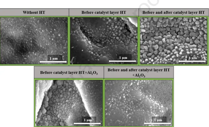
Fig. 2: SEM images of catalyst particles on substrates during blank synthesis from different heat-treatments (HT)
Based on the SEM images (Fig. 2), it was observed that the catalyst particles were evenly distributed on the surface of the substrate in all cases. Also, in the case where the substrate was not heat-treated before the catalyst layer formation, the catalyst particles were probably melted into the substrate, and thus the smallest particle size was observed. While in the case where the substrate was heat-treated before the catalyst layer was built, the diameter of the catalyst particles was larger as well as better separated on the substrate surface, which may be due to the heat-treatment forming a titanium-dioxide layer on the substrate surface. In cases where there was the aluminum oxide layer on the substrate surface, significant
Journal Pre-proof
difference was not observed. After these measurements, TEM and Raman measurements were performed to obtain information on the diameter as well as the graphitic properties of the CNTs.
Fig. 3: HRTEM images of CNT forests synthesized during different heat-treatments (HT) used in the synthesis.
Fig. 4: Raman spectroscopy measurements of CNT forests synthesized over substrates prepared with different heat-treatments.
Journal Pre-proof
Based on the TEM measurements (Fig. 3), it can be concluded that the diameter of the CNTs was almost the same in all cases (Table 1). In the absence of heat-treatment on the substrate, more catalyst particles were observed on the TEM images, due to the fact that not only the root growth mechanism of CNT forests was present during the synthesis, but the tip growth as well [29]. This phenomenon was presumably due to the weak interaction between the catalyst particles and the substrate, so it was possible for the catalyst particles to come apart from the substrate. Based on the Raman measurements (Fig. 4), the CNT forests were containing almost the same amount of defect location, of which the calculated ID/IG ratios were shown in Table 1. Based on the evaluated data, the fewest amount of defect location was observed in the case when heat-treatment was not performed during the catalyst layer construction.
3.2. The effect of catalyst ink ratio in the growth of CNT forests
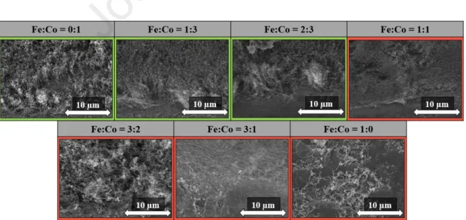
In these syntheses, the different catalyst ratios were investigated in order to obtain information on the effect of this parameter and how it influences the formation of CNT forests on the substrate, because the Fe:Co = 1:1 ratio was most commonly used in the literature [30]. Other synthesis parameters were the same as described in the experimental section. The catalyst ratios were as follows: Fe:Co = 0:1; 1:3; 2:3; 1:1; 3:2; 3:1; 1:0. SEM images were also taken in this series, as shown in Fig. 6.
Fig. 5: SEM images of CNT forests growth on titanium substrate using different catalyst ratios.
Fe:Co 0:1 1:3 2:3 1:1 3:2 3:1 1:0
Journal Pre-proof
h (µm) 2.7 ± 0.4 6.4 ± 0.8 5.9 ± 0.8 - - - - Table 2: The height of CNT forests from SEM at different catalyst ratios.
Based on the SEM images (Fig. 5), using samples with different catalyst ratios on the substrate, the characteristic structure of CNT forests could be observed only three times on the substrate, which are Fe:Co = 0:1, Fe:Co = 1:3, and Fe:Co = 2:3, while in the other cases only CNTs were grown on the substrate surface and the CNTs were not able to align into a CNT forest structure. Based on these results, it can be concluded that if cobalt was present in larger amount in the catalyst solution, the forest structure was observed only in those cases.
This may be due to the fact that using cobalt catalyst on a titanium substrate is more favorable for the formation of CNT forest based on literature data [31]. By contrast it was found that if iron precursor was present in larger amount in the catalyst ink, only unaligned CNTs were growth on the substrate. Examining the height of CNT forests again, the highest forest could be observed with Fe:Co = 1:3 (Table 2), where the largest amount of cobalt precursor was in the catalyst solution which differs from the Fe:Co = 1:1 ratio most commonly used in the literature.
3.3. Effect of catalyst ink concentration on the growth of CNT forests
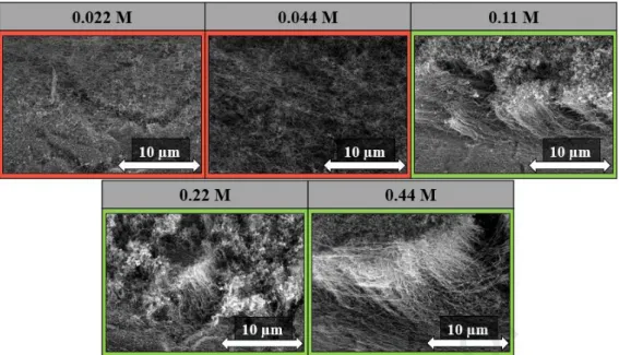
In the next experiments, we aimed to obtain information on the effect of catalyst ink concentration on the growth of CNT forest. To this end, we used concentrations lower as well as higher concentrations, than the reference concentration to investigate the lowest and also the upper concentration limit with which it was still possible to produce CNT forests. For these reasons, the concentration of ink was varied as follows: 0.022 M, 0.044 M, 0.11 M, 0.22 M, and 0.44 M, and the other parameters used during the synthesis were the same as described in the experimental section.
Journal Pre-proof
Fig. 6: SEM images of CNT forests grown on titanium substrate using different ink concentrations.
Form the SEM results (Fig. 6), it can be concluded that at the concentrations lower than the reference concentration (0.11 M) the forest structure was not observed at all, only unarrayed CNTs can be seen on the substrate. Based on this finding, it can be concluded that this is the lower limit at which the forest structure appeared on the substrate. This may be due to less catalyst deposition onto the surface of the substrate, which was not sufficient to form the forest structure. In all cases, where a concentration higher than the reference concentration was used on the substrate, the forest structure can be observed. However, in the case of 0.11 M, the CNT forest was much more structured, and the height of the CNT forests was 8.0 ± 1.0 µm. While at the highest concentration, which was 0.44 M, the CNT forests had twice the height, while at 0.22 M it was lower, which may be due to the water vapor present in the system, which oxidized the CNTs thus decreasing their height. Based on the results, it can be concluded that the 0.11 M concentration was the most suitable for the formation of the CNT forest structure with this production method.
3.4. The effect of reaction temperature on the growth of CNT forests
In this case, we wanted to obtain information how the reaction temperature used during the synthesis affects the growth of CNT forests on the substrate. From the literature, the ideal synthesis temperature for titanium substrate seems to be 700 °C, however, if it was possible to produce CNT forests at lower temperatures, the forest structure could be achieved
Journal Pre-proof
with less energy investment [32]. For these reasons, the temperature was varied between 400
°C and 800 °C, the other synthesis parameters were the same as described in the experimental section. About the samples SEM images were recorded which are shown in Fig. 7.
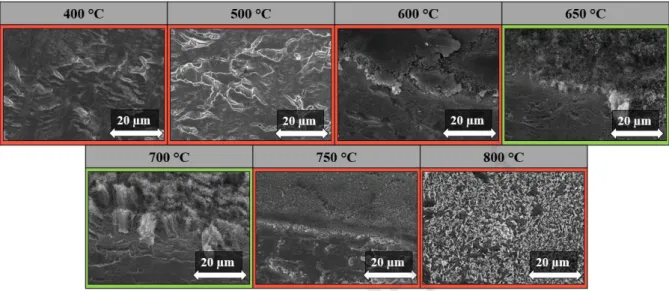
Fig. 7: SEM images of CNT forests synthesized at different reaction temperatures.
From the SEM measurements (Fig. 7), it can be concluded that at low temperatures, such as the range of 400-600 °C, the forest structure did not appear on the substrates. A possible reason could be that, at too low temperature, the carbon deposition has not occurred on the catalyst particles due to the reactivity of carbon source, so the growth of CNT could not start on the substrate surface. Also in the literature generally higher temperatures are used for the syntheses of CNT production [33]. However, at 650 °C and 700 °C, the forest structure can already be observed, consequently this temperature was ideal for the growth of CNT forests on titanium substrate [10]. It can also be observed that the most suitable temperature for the production of CNT forests was 700 ° C, since at this temperature the height of the CNT forest was 11.0 ± 1.5 µm, however, it is possible for 650 °C to reach the CNT forest structure. At higher temperatures (750 - 800 °C) CNTs can be not observed on the substrate surface, only amorphous carbon, which may be due to the fact that in this case it is conceivable that homogeneous decomposition of ethylene (in addition to the catalytic) starts in parallel and deposits on the substrate, which inhibits the growth of CNT and amorphous carbon is formed on the substrate.
Journal Pre-proof
3.5. The effect of reaction time used in the growth of CNT forests
In this case, the reaction time used during the synthesis was investigated, where shorter and longer times (10, 20, 40 and 50 minutes) were used compared to the 30 minutes reference. The reason why this parameter was examined if we could reduce the reaction time, the energy investment would be reduced if we could achieve the desired CNT forest structure in a shorter period. SEM images were taken, which are shown in Fig. 8.
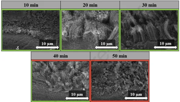
Fig. 8: SEM images of CNT forests at different reaction times used during synthesis.
Fig. 9: The height of CNT forests from SEM at different reaction times.
Based on the results, it can be said that the structure characteristic of the CNT forest can be observed during the application of all reaction times except for the 50 min synthesis. It
Journal Pre-proof
can be observed that at low reaction time (10 min) the height of CNT forests was only 3.0 ± 0.3 µm, which may be due to the fact that only a small amount of carbon could enter the system in this short period of time, thus affecting the height of CNT forests and in this case, even the water vapor could not use its effect of activating the catalyst particles [34]. Also, the structure of CNT forests was not so prominent. Nearly the same CNT forest height can be observed at 20- and 30-min synthesis times (Fig. 9), however, structurally the most ordinate structure can be observed at 30 min reaction time, these results suggest that this parameter was ideal for growing CNT forests on titanium substrate. While a reaction time of 40 minutes, the height of the CNT forests is already decreasing and the CNT forest structure is not so dense in this case, due to the fact that the water vapor present in the system has started to decompose the CNTs, thus reducing their height as well. While during the 50 min reaction time, only CNTs can be observed on the substrate, which may be due to the fact that in this case the CNTs were no longer arranged in CNT forest structure because the catalyst was tired in case of long reaction time so the CNT was not grown further and so the oxidative properties of water vapor was started to dominate.. Based on the results, it can be concluded that even with a low reaction time such as 10 min, it is possible to achieve the CNT forest structure, which might also simplify the synthesis.
3.6. The effect of hydrogen used in the growth of CNT forests
In the next experimental step, the effect of hydrogen was investigated in three different ways. In the first case, the hydrogen was not present at all in the system during synthesis, in the second case for only 5 minutes while reducing the catalyst particles, and in the third case during the entire content of the synthesis. It is also important to study this parameter because it was an important factor in the production of CNT forests to provide a reductive environment in the system to which hydrogen is most often applied [35]. However, without the presence of hydrogen, the synthesis could have been simplified, and the growth of CNT forests could be safer. SEM images were taken of the prepared samples, which are shown in Fig. 10.
Journal Pre-proof
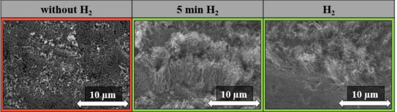
Fig. 10: SEM images of CNT forests without and 5 min and with hydrogen used during synthesis.
Based on the SEM images (Fig. 10), in the case where hydrogen was not present in the system, the structure of CNT forest cannot be observed on the substrate. This may be because hydrogen did not reduce the catalyst particles on the surface of the substrate, so CNT growth could not start. Based on the literature data, a reducing agent is required in the system to provide a reducing environment, which is most commonly hydrogen [36]. In the case when hydrogen was present in the system for only 5 minutes (the preliminary treatment before carbon source feed), the characteristic structure of the CNT forest could be observed, and the height of the CNT forests was 6.1 ± 0.7 µm. This is important information that hydrogen was needed in the system, but only for a short time to reduce the catalyst particles, then no longer indispensably needed for the rest of the synthesis. When hydrogen was present in the system during the entire synthesis, the characteristic structure of CNT forest was also observed and in this case the height of CNT forests was 4.8 ± 0.7 µm, that is, the height of the CNT forests decreased in the presence of hydrogen, which may be due to fact that hydrogen is able to react with carbon in the system [35], which can reduce the height of the CNT forests.
However, it can be concluded that it was not necessary for 5 min hydrogen to be present in the system, which can simplify the achievement of forest structure.
3.7. The effect of water vapor used in the growth of CNT forests
With this sample series, we aimed to investigate the effect of water vapor on forest structure formation because, according to literature data [37], water vapor helped the growth of CNT forests as well as activating the catalyst on the substrate surface thus amorphous carbon was eliminated from the system. It is an essential information whether the structure of the CNT forest formed on the substrate during the synthesis is dependent on the absence or
Journal Pre-proof
presence of water vapor in the system. The synthesis parameters were the same as described in the experimental section. SEM images were taken of the samples as shown in Fig. 10.
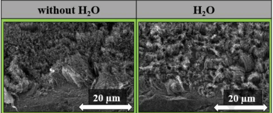
Fig. 11: SEM images of CNT forests without and with water vapor during CVD synthesis.
Based on the SEM images (Fig. 11), it can be concluded that in both cases the forest structure appeared on the substrate. In the absence of water vapor, the forest structure was denser, and the height of the CNT forests was 7.0 ± 0.9 µm. While in the presence of water vapor, the height of CNT forests was 5.5 ± 0.9 µm and the forest structure was less complex.
This may be due to the fact that the presence of water vapor in the system has begun to break down the CNT forests, so their height has decreased, and their structure was not so dense.
According to literature data, water vapor helped the growth of CNTs via catalyst particle reactivation, however, it oxidizes not only amorphous carbon in the system but CNT walls as well as [38]. However, without water vapor present in the system, the height of the CNT forests was higher, the reason is probably the same as described above. Based on these results, it can be said that the structure of the CNT forest can be achieved even in the absence of water vapor, with which it is possible to simplify the growth of CNT forests.
3.8. The effect of different carbon sources used in the growth of CNT forests
Finally, we investigated whether ethylene as a carbon source could be excluded if different carbon sources were introduced into the system by the bubbling method. For this reason, acetone, ethanol, palinka, cyclohexane, diethyl ether, and ethyl acetate were used as carbon sources and the carbon ratio was constant. The synthesis parameters were the same as described in the experimental section, except that water vapor was no present in the system.
The aim of this study was that if we can replace the ethylene carbon source with other natural carbon compounds, this would simplify the synthesis, different carbon sources have been
Journal Pre-proof
used in the literature to produce CNT forests instead of the usual acetylene, ethylene [24,39].
SEM images of the samples were taken as shown in Fig. 12.
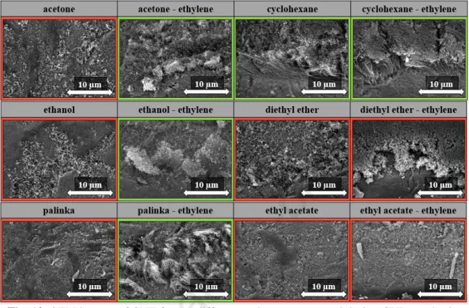
Fig. 12: SEM images of CNT forests different carbon sources used during CVD synthesis.
acetone acetone – ethylene ethanol ethanol - ethylene
h (µm) - 1.7 ± 0.3 - 3.9 ± 1.5
palinka palinka - ethylene cyclohexane cyclohexane - ethylene
h (µm) - 4.6 ± 0.7 4.2 ± 0.8 4.8 ± 0.5
Table 3: The height of CNT forests from SEM by different carbon sources.
Based on the results, it was observed that in the absence of ethylene, the CNT forest structure appeared only during the application of cyclohexane, where the height of CNT forest was 4.2 ± 0.8 µm. However, the CNTs observed in the other cases on the substrate, but the CNTs were not arranged in the CNT forest structure. This may be due to less carbon source entering in the system. For these reasons, syntheses were also performed when ethylene was used in the system at the same flow rate in addition to the natural carbon source.
Thus, the CNT forest structure on the surface of the substrate, acetone, ethanol, palinka, and cyclohexane can be observed in several cases on SEM images (Fig. 12), which may be due to
Journal Pre-proof
literature data that the system requires a non-oxygen-containing carbon compound as well as only a small amount of oxygen-containing carbon compound to aid in the decomposition of the amorphous carbon and to activate the catalyst [40]. The height of these forests was remarkably low (Table 3), which may be important for further applications. Based on the results, it can be said that it was possible to form CNTs on the substrate using different carbon sources, however, they depend on several parameters.
4. Conclusion
Summarizing the results, it can be concluded that it was possible to produce CNT forests with a simple layering method. Also, there was no need for the presence of a support oxide layer on the substrate, which plays an important role in the production of CNT forests, so it is possible to grow CNT forests directly on titanium substrate. In addition, there was no need for a heat-treatment phase to stabilize the catalyst layer on the surface of the substrate, thus making the production of CNT forests easier. In addition, it can be said that CNT forests can be grow at lower temperatures (650 °C) and with lower reaction times (10 min), because of which less energy was required to achieve the desired product. Also, various parameters such as concentration and catalyst ratio play an influential role in the production of CNT forests, which differs from the parameters frequently was used in the literature. Based on the results, it can be concluded that by excluding water vapor as well as hydrogen, the growth of CNT forests on the substrate was possible, which the syntheses was made safer. Finally, in addition to the ethylene carbon source, it was also possible to produce CNT forests with other natural carbon compounds, which could open a new way in the production of CNT forests.
Acknowledgements
This work was supported by the ÚNKP-20-3-SZTE-557 New National Excellence Program of the Ministry for Innovation and Technology.
Journal Pre-proof
References
[1] A. Zandi, A. Gilani, H. Ghafoori fard, J. Koohsorkhi, An optimized resistive CNT- based gas sensor with a novel configuration by top electrical contact, Diam. Relat.
Mater. 93 (2019) 224–232. doi:10.1016/j.diamond.2019.01.020.
[2] J. Sheng, X. Zeng, Q. Zhu, Z. Yang., X. Zhang, Facile fabrication of CNT-based chemical sensor operating at room temperature, Mater. Res. Express. 4 (2017) 125701.
doi:10.1088/2053-1591/aa9ac7.
[3] S. Park, M. Vosguerichian, Z. Bao, A review of fabrication and applications of carbon nanotube film-based flexible electronics, Nanoscale. 5 (2013) 1727–1752.
doi:10.1039/c3nr33560g.
[4] R. Reit, J. Nguyen, W.J. Ready, Growth time performance dependence of vertically aligned carbon nanotube supercapacitors grown on aluminum substrates, Electrochim.
Acta. 91 (2013) 96–100. doi:10.1016/j.electacta.2012.12.058.
[5] W.Z. Li, S.S. Xie, L.X. Qian, B.H. Chang, B.S. Zou, W.Y. Zhou, R.A. Zhao, G. Wang, Large-Scale Synthesis of Aligned Carbon Nanotubes, Science (80-. ). 274 (1996) 1701–1703. doi:10.1126/science.274.5293.1701.
[6] A. Szabó, E. Kecsenovity, Z. Pápa, T. Gyulavári, K. Németh, E. Horvath, K. Hernadi, Influence of synthesis parameters on CCVD growth of vertically aligned carbon nanotubes over aluminum substrate, Sci. Rep. 7 (2017) 1–11. doi:10.1038/s41598-017- 10055-0.
[7] Y. Miyajima, S.Y. Komatsu, M. Mitsuhara, S. Hata, H. Nakashima, N. Tsuji, Microstructural change due to isochronal annealing in severely plastic-deformed commercial purity aluminium, Philos. Mag. 95 (2015) 1139–1149.
doi:10.1080/14786435.2015.1021400.
[8] G. Atthipalli, Y. Tang, A. Star, J.L. Gray, Electrochemical characterization of carbon nanotube forests grown on copper foil using transition metal catalysts, Thin Solid Films. 520 (2011) 1651–1655. doi:10.1016/j.tsf.2011.08.105.
[9] C. Oka, K. Odagiri, H. Nagano, Effect of wettability of a porous stainless steel on thermally induced liquid-vapor interface behavior, Surf. Topogr. Metrol. Prop. 5 (2017). doi:10.1088/2051-672X/aa9499.
[10] A. Szabó, P. Andricević, Z. Pápa, T. Gyulavári, K. Németh, E. Horvath, L. Forró, K.
Hernadi, Growth of CNT Forests on Titanium Based Layers, Detailed Study of Catalysts, Front. Chem. 6 (2018) 1–9. doi:10.3389/fchem.2018.00593.
Journal Pre-proof
[11] P. Mauron, C. Emmenegger, A. Zuttel, C. Nutzenadel, L. Schlapbach, S ynthesis of oriented nanotube films by chemical vapor deposition, Carbon Nanotub. 40 (2002) 1339–1344. doi:10.1016/S0008-6223(01)00295-0.
[12] L. Nanai, A. Szabó, T. Gyulavári, J. Budai, K. Hernádi, Manual spray coating: A cheap and effective method to build catalyst layers for carbon nanotube forest growth, Thin Solid Films. 689 (2019) 137491–137499. doi:10.1016/j.tsf.2019.137491.
[13] Z. Pápa, E. Kecsenovity, D. Fejes, J. Budai, Z. Toth, K. Hernadi, Height and diameter dependence of carbon nanotube forests on the porosity and thickness of catalytic layers, Appl. Surf. Sci. 428 (2018) 885–894. doi:10.1016/j.apsusc.2017.09.206.
[14] A. Szabó, L.P. Bakos, D. Karajz, T. Gyulavári, Z.-R. Tóth, Z. Pap, I.M. Szilágyi, T.
Igricz, B. Parditka, Z. Erdélyi, K. Hernádi, Decoration of Vertically Aligned Carbon Nanotubes with Semiconductor Nanoparticles Using Atomic Layer Deposition, Materials (Basel). 12 (2019) 1095–1108. doi:10.3390/ma12071095.
[15] S. Dörfler, I. Felhösi, I. Kék, T. Marek, H. Althues, S. Kaskel, L. Nyikos, Tailoring structural and electrochemical properties of vertical aligned carbon nanotubes on metal foil using scalable wet-chemical catalyst deposition, J. Power Sources. 208 (2012) 426–433. doi:10.1016/j.jpowsour.2012.02.067.
[16] C. Mattevi, C.T. Wirth, S. Hofmann, R. Blume, M. Cantoro, C. Ducati, C. Cepek, A.
Knop-Gericke, S. Milne, C. Castellarin-Cudia, S. Dolafi, A. Goldoni, R. Schlögl, J.
Robertson, In-situ X-ray Photoelectron Spectroscopy Study of Catalyst- Support Interactions and Growth of Carbon Nanotube Forests, J. Phys. Chem. C. 112 (2008) 12207–12213. doi:10.1021/jp802474g.
[17] S. Noda, K. Hasegawa, H. Sugime, K. Kakehi, Z. Zhang, S. Maruyama, Y.
Yamaguchi, Millimeter-Thick Single-Walled Carbon Nanotube Forests: Hidden Role of Catalyst Support, Japanese J. Appl. Physics, Part 2 Lett. 46 (2007) L399–L401.
doi:10.1143/JJAP.46.L399.
[18] L. Dong, J. Jiao, S. Foxley, D.W. Tuggle, C.L. Mosher, G.H. Grathoff, Effects of Hydrogen on the Formation of Aligned Carbon Nanotubes by Chemical Vapor Deposition, J. Nanosci. Nanotechnol. 2 (2002) 155–160. doi:10.1166/jnn.2002.083.
[19] Q.N. Pham, L.A.S. Larkin, C.C. Lisboa, C.B. Saltonstall, L. Qiu, J.D. Schuler, T.J.
Rupert, P.M. Norris, Effect of growth temperature on the synthesis of carbon nanotube arrays and amorphous carbon for thermal applications, Phys. Status Solidi Appl.
Mater. Sci. 214 (2017) 1–7. doi:10.1002/pssa.201600852.
[20] K.-Y. Lee, S. Honda, M. Katayama, T. Miyake, K. Himuro, K. Oura, J.-G. Lee, H.
Journal Pre-proof
Mori, T. Hirao, Vertically aligned growth of carbon nanotubes with long length and high density, J. Vac. Sci. Technol. B Microelectron. Nanom. Struct. 23 (2005) 1450.
doi:10.1116/1.1941187.
[21] C.P. Huynh, S.C. Hawkins, M. Redrado, S. Barnes, D. Lau, W. Humphries, G.P.
Simon, Evolution of directly-spinnable carbon nanotube growth by recycling analysis, Carbon N. Y. 49 (2011) 1989–1997. doi:10.1016/j.carbon.2011.01.024.
[22] A.B. Suriani, A.A. Azira, S.F. Nik, R. Md Nor, M. Rusop, Synthesis of vertically aligned carbon nanotubes using natural palm oil as carbon precursor, Mater. Lett. 63 (2009) 2704–2706. doi:10.1016/j.matlet.2009.09.048.
[23] Y. Li, G. Xu, H. Zhang, T. Li, Y. Yao, Q. Li, Z. Dai, Alcohol-assisted rapid growth of vertically aligned carbon nanotube arrays, Carbon N. Y. 91 (2015) 45–55.
doi:10.1016/j.carbon.2015.04.035.
[24] R. Kumar, R.K. Singh, D.P. Singh, Natural and waste hydrocarbon precursors for the synthesis of carbon based nanomaterials: Graphene and CNTs, Renew. Sustain.
Energy Rev. 58 (2016) 976–1006. doi:10.1016/j.rser.2015.12.120.
[25] H. Kimura, J. Goto, S. Yasuda, S. Sakurai, M. Yumura, D.N. Futaba, K. Hata, The infinite possible growth ambients that support single-wall carbon nanotube forest growth, Sci. Rep. 3 (2013) 1–6. doi:10.1038/srep03334.
[26] C. Masarapu, B.Q. Wei, Direct growth of aligned multiwalled carbon nanotubes on treated stainless steel substrates, Langmuir. 23 (2007) 9046–9049.
doi:10.1021/la7012232.
[27] M. Ştefănescu, T. Dippong, M. Stoia, O. Ştefǎnescu, Study on the obtaining of cobalt oxides by thermal decomposition of some complex combinations, undispersed and dispersed in SiO 2 matrix, J. Therm. Anal. Calorim. 94 (2008) 389–393.
doi:10.1007/s10973-008-9111-2.
[28] A. Roussey, N. Venier, H. Fneich, L. Giardella, T. Pinaud, S. Tahir, M. Pelaez- Fernandez, R. Arenal, A. Mehdi, V. Jourdain, One-pot preparation of iron/alumina catalyst for the efficient growth of vertically-aligned carbon nanotube forests, Mater.
Sci. Eng. B Solid-State Mater. Adv. Technol. 245 (2019) 37–46.
doi:10.1016/j.mseb.2019.05.005.
[29] M. Kumar, Y. Ando, Chemical Vapor Deposition of Carbon Nanotubes : A Review on Growth Mechanism and Mass Production, J. Nanoparticle Res. 10 (2010) 3739–3758.
doi:10.1166/jnn.2010.2939.
[30] S.A. Shokry, A.K. El Morsi, M.S. Sabaa, R.R. Mohamed, H.E. El Sorogy, Study of the
Journal Pre-proof
productivity of MWCNT over Fe and Fe–Co catalysts supported on SiO2, Al2O3 and MgO, Egypt. J. Pet. 23 (2014) 183–189. doi:10.1016/j.ejpe.2014.05.005.
[31] M. Ahmad, S.R.P. Silva, Low temperature growth of carbon nanotubes – A review, Carbon N. Y. 158 (2020) 24–44. doi:10.1016/j.carbon.2019.11.061.
[32] G. Li, S. Chakrabarti, M. Schulz, V. Shanov, Growth of aligned multiwalled carbon nanotubes on bulk copper substrates by chemical vapor deposition, J. Mater. Res. 24 (2009) 2813–2820. doi:10.1557/jmr.2009.0339.
[33] C.J. Lee, J. Park, Y. Huh, J. Yong Lee, Temperature effect on the growth of carbon nanotubes using thermal chemical vapor deposition, Chem. Phys. Lett. 343 (2001) 33–
38. doi:10.1016/S0009-2614(01)00680-7.
[34] S.P. Patole, P.S. Alegaonkar, H.-C. Lee, J.-B. Yoo, Optimization of water assisted chemical vapor deposition parameters for super growth of carbon nanotubes, Carbon N. Y. 46 (2008) 1987–1993. doi:10.1016/j.carbon.2008.08.009.
[35] Y. Li, K. Ji, Y. Duan, G. Meng, Z. Dai, Effect of hydrogen concentration on the growth of carbon nanotube arrays for gecko-inspired adhesive applications, Coatings.
7 (2017) 1–12. doi:10.3390/coatings7120221.
[36] D. Fejes, Z. Pápa, E. Kecsenovity, B. Réti, Z. Toth, K. Hernadi, Super growth of vertically aligned carbon nanotubes on pulsed laser deposited catalytic thin films, Appl. Phys. A Mater. Sci. Process. 118 (2015) 855–861. doi:10.1007/s00339-014- 8965-3.
[37] K. Hata, D.N. Futaba, K. Mizuno, T. Namai, M. Yumura, S. Iijima, Water-Assisted Highly Efficient Synthesis of Impurity-Free Single-Walled Carbon Nanotubes, Science (80-. ). 306 (2004) 1362–1364. doi:10.1126/science.1104962.
[38] G.D. Nessim, A. Al-Obeidi, H. Grisaru, E.S. Polsen, C. Ryan Oliver, T. Zimrin, A.
John Hart, D. Aurbach, C. V. Thompson, Synthesis of tall carpets of vertically aligned carbon nanotubes by in situ generation of water vapor through preheating of added oxygen, Carbon N. Y. 50 (2012) 4002–4009. doi:10.1016/j.carbon.2012.04.043.
[39] K. Hernadi, A. Fonseca, J.B. Nagy, A. Siska, I. Kiricsi, Production of nanotubes by the catalytic decomposition of different carbon-containing compounds, Appl. Catal. A Gen. 199 (2000) 245–255. doi:10.1016/S0926-860X(99)00561-X.
[40] D.N. Futaba, J. Goto, S. Yasuda, T. Yamada, M. Yumura, K. Hata, General rules governing the highly efficient growth of carbon nanotubes, Adv. Mater. 21 (2009) 4811–4815. doi:10.1002/adma.200901257.
Journal Pre-proof
Figure and Table captions
Fig. 1: SEM images of CNT forests synthesized over substrates with different heat- treatments (HT) applied during catalyst layer building.
Fig. 2: SEM images of catalyst particles on substrates during blank synthesis from different heat-treatments (HT)
Fig. 3: TEM images of CNT forests synthesized during different heat-treatments (HT) used in the synthesis.
Fig. 4: Raman spectroscopy measurements of CNT forests synthesized over substrates prepared with different heat-treatments.
Fig. 5: SEM images of CNT forests growth on titanium substrate using different catalyst ratios.
Fig. 6: SEM images of CNT forests grown on titanium substrate using different ink concentrations.
Fig. 7: SEM images of CNT forests synthesized at different reaction temperatures.
Fig. 8: SEM images of CNT forests at different reaction times used during synthesis.
Fig. 9: The height of CNT forests from SEM at different reaction times.
Fig. 10: SEM images of CNT forests without and 5 min and with hydrogen used during synthesis.
Fig. 11: SEM images of CNT forests without and with water vapor during CVD synthesis.
Fig. 12: SEM images of CNT forests different carbon sources used during CVD synthesis.
Table 1: The height of the CNT forests (h), the ID/IG band intensity ratios obtained from Raman spectra, the diameter of CNT from TEM, and the diameter of catalyst particles from pre synthesized.
Table 2: The height of CNT forests from SEM at different catalyst ratios.
Table 3: The height of CNT forests from SEM by different carbon sources.
Journal Pre-proof
Simplification of the CCVD method used in the growth of carbon nanotube forests on titanium substrate
Anna Szabóa, Lilla Nánaia, Zsejke Réka Tótha,b, Klara Hernadia,c1
aDepartment of Applied and Environmental Chemistry, University of Szeged, H-6720 Szeged, Rerrich Béla tér 1, Hungary
bNanostructured Materials and Bio-Nano-Interfaces Center, Institute for Interdisciplinary Research on Bio-Nano-Sciences, Babeș-Bolyai University, Treboniu Laurian 42, RO-400271, Cluj-Napoca, Romania
cInstitute of Physical Metallurgy, Metal Forming and Nanotechnology, University of Miskolc, 3515 Miskolc-Egyetemváros, Hungary;
Highlights
Demonstration of possible simplification of CCVD synthesis in CNT forest growth
CNT forest production directly on titanium substrate
Investigation of the effect of parameters used in CCVD synthesis
Applying a simple layer building method to build the catalyst layer
1 Corresponding author: hernadi@chem.u-szeged.hu
Journal Pre-proof
Simplification of the CCVD method used in the growth of carbon nanotube forests on titanium substrate
Anna Szabóa, Lilla Nánaia, Zsejke Réka Tótha,b, Klara Hernadia,c1
aDepartment of Applied and Environmental Chemistry, University of Szeged, H-6720 Szeged, Rerrich Béla tér 1, Hungary
bNanostructured Materials and Bio-Nano-Interfaces Center, Institute for Interdisciplinary Research on Bio-Nano-Sciences, Babeș-Bolyai University, Treboniu Laurian 42, RO-400271, Cluj-Napoca, Romania
cInstitute of Physical Metallurgy, Metal Forming and Nanotechnology, University of Miskolc, 3515 Miskolc-Egyetemváros, Hungary;
Declaration of interests
☒The authors declare that they have no known competing financial interests or personal relationships that could have appeared to influence the work reported in this paper.
☐The authors declare the following financial interests/personal relationships which may be considered as potential competing interests:
On behalf of all authors,
Klara Hernadi
corresponding author
1 Corresponding author: hernadi@chem.u-szeged.hu