SOLAR CONCENTRATORS
FOR - HIGH TEMPERATURE SPACE POWER SYSTEMS
Donald H. McClelland 2 Electro-Optical Systems, Inc.
Pasadena, California Abstract
Basic problems in the development of lightweight, high efficiency, solar concentrating m i r r o r s for space power s y s - tems are discussed· Current requirements are for m i r r o r s having specific weights less than 0. 3 lb/ft^ and efficiencies above 70 percent for absorber temperatures between 1200°F and 3000°F. Various concentrator and absorber configura- tions are compared both on the basis of idealized performance and in regard to performance degradation due to geometric e r r o r s . Concentrator structural design classifications are presented and are related to fabrication techniques, m a t e r i - als, and reflective surfacing methods. Orientation r e q u i r e - ments and the effects of the space environment are considered.
Tests are presented for determining collector performance and for evaluating m i r r o r surface quality.
Introduction
The rapid development of space technology has given rise to urgent requirements for secondary power systems capable of supplying sizeable quantities of electrical energy for long-term missions. The only two basic energy sources which presently appear capable of meeting these require- ments are solar energy and nuclear energy. For output power levels up to perhaps twenty kilowatts, solar power systems may be lighter, safer and less expensive than nuclear systems.
Many types of solar energy conversion systems, parti- cularly at higher power levels, require concentration of the incident energy in order to obtain high temperatures.
Typical systems requiring concentration include thermi- onic emitters and Rankine cycle turboelectric systems.
For many applications, the concentrating m i r r o r is 1. Presented at the Space Power Systems Conference, Santa Monica, California, September 27-30, 1960.
2. Manager, Energy Conversion and Regulation Department, Advanced Power Systems Division.
probably the heaviest component in the power system.
Until recently, it has also received the least developmental effort. The ultimate utility of solar-thermal power systems depends largely on the ability to construct lightweight,
accurate and (for large power systems) foldable solar concentrators.
Concentrator size and geometry is directly related to system parameters such as conversion efficiency, power level, and maximum cycle temperature. The absorber geometry, the temperature desired at the outlet of the absorber and the amount of heat withdrawn from the
absorber also directly affect concentrator design. In fact, concentrator performance can only be clearly understood when considered in combination with an absorber in order to take account of reradiation losses. Although this paper will emphasize concentrator development problems,
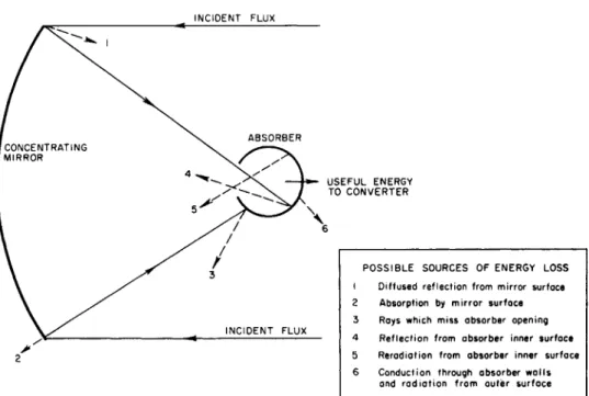
absorber characteristics will be included to the extent necessary to define concentrator performance. Figure 1 is a schematic collector system showing the relative roles played by the concentrator and absorber in radiation
collection.
Basic Concentrator and Absorber Configurations Many basic configurations have been suggested for solar energy concentrators, depending on the application,
including:
a. Paraboloid of revolution b. Parabolic cylinder c. Hemisphere d. Circular cylinder e. Fresnel m i r r o r f. Fresnel lens
g. Conical m i r r o r
h. Dual m i r r o r systems (Cassegrainian) using either paraboloidal or hemispherical primary m i r r o r s
The first four are illustrated in Figure 2. A number of different absorber configurations have also been suggested, including:
a. Black body cavity
b. Flat plate (with or without spectrally selective surfaces)
c. Convex or concave hemisphere (with or without spectrally selective surfaces)
Under most conditions the paraboloid of revolution con- centrator and the black body cavity absorber provide the greatest performance. Under ideal conditions some dual m i r r o r systems can slightly exceed the performance capa- bilities of the single paraboloid. However, dual m i r r o r systems would undoubtedly be inferior in practice because their performance is more sensitive to geometric e r r o r s .
Because it can be made flat, the Fresnel m i r r o r , which has performance capabilities almost as great as the paraboloid, may offer considerable advantage for appli- cations where folding is a serious problem.
The geometry of each concentrator configuration must be specified in such a way as to optimize collector per- formance and minimize weight. For a paraboloid of revolution, the most important geometric parameter (in addition to the diameter) is the ratio of diameter to focal length (D/f). In the literature this is frequently expressed as the rim angle, Θ, which is the angle subtended by the radius of the m i r r o r rim as seen from the focal point.
For a cavity absorber, the primary design parameter is the cavity opening size, This is optimized for any given temperature to produce maximum collector efficiency.
The ability of the concentrator to produce high temper- atures with high efficiency is directly related to the con- centration ratio, C, where
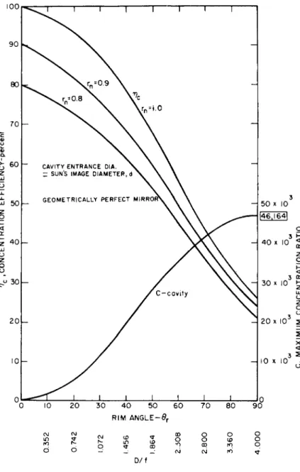
P __ Radiant flux density received by absorber Radiant flux density impinging on concentrator The maximum possible concentration ratio is achieved by a geometrically perfect paraboloid of revolution reflector, and is illustrated in Figure 3 (Ref. 1). The concentration efficiency, also shown in Figure 3, is:
__ Radiant energy received by cavity
^C Radiant energy impinging on concentrator These quantities are plotted in terms of the m i r r o r rim angle. The actual concentration ratio is degraded by geo- metric inaccuracies in the m i r r o r surface.
For power system usage, a rim angle between 40 and 60 (D/f = 1. 66 to 2. 3) is satisfactory for many appli- cations. The concentration ratio is greatly reduced for rim angles less than 40 , while rim angles greater than 60 require a great increase in m i r r o r surface area in
order to achieve only a slight increase in concentration (Ref. Z).
The effect of m i r r o r surface e r r o r s is also reduced in this rim angle region. Light reflected from the periphery of a high rim angle m i r r o r strikes the focal plane at such an oblique angle as to be nearly useless.
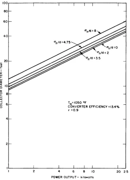
The maximum attainable temperatures and concentration ratios for several concentrators are shown in Figure 4 (Ref. 3) as functions of heat withdrawn from the absorber. The parab- oloid of revolution is clearly superior for high temperature application. Although not shown on this figure, Fresnel m i r - ror performance approaches that of the paraboloid. Figure 5 (Ref. 4) shows the concentrator diameters required for typical solar power systems. The converter efficiency in this case is assumed to be 13.4 percent. The parameter, σ^/d is a measure of the geometric accuracy of the m i r r o r surface (σ^/d = 0 for a perfect m i r r o r ) .
In order to quantitatively evaluate the performance of a given concentrator, we must be able to determine the con- centrator-absorber efficiency, which is defined as:
Thermal energy transferred to the working fluid
^C-A " Total solar flux intercepted by concentrator This quantity can only be discussed by considering the characteristics of the absorber. In conjunction with a paraboloid or Fresnel concentrator, the cavity type of
absorber generally produces highest performance even when compared with flat plate and hemisphere concentrators using advanced spectrally selective surfaces, as shown in Fig. 6 (Ref. 5). Furthermore, the cavity absorber is most con- venient from the standpoints of thermal energy storage and heat removal. The characteristics of the cavity absorber are such that it efficiently absorbs incoming solar radiation, but inhibits re radiation losses from the heated inner surface because of the relatively small cavity opening. For maxi- mum efficiency, the cavity opening size must be optimized for the particular concentrator and cavity temperature.
The way this is done will be discussed in the next section and is analyzed in detail in Ref. 6.
Performance of Real Collector Systems
All real collectors deviate from ideal conditions be- cause of m i r r o r surface irregularities, imperfect m i r r o r reflectivity, misalignment with the sun, concentrator- absorber misalignment and a periodic distortion of the system due to thermal cycling. Angular and linear devia- tions of the m i r r o r surface elements from their ideal
positions constitute the most important source of e r r o r . These deviations are the result of imperfect fabrication methods. It is convenient to consider two general types of error:
a. Local deviations of the concentrator surface.
(For computational purposes these are fre- quently assumed to be randomly distributed. ) b. Large bias e r r o r s such as over-all bending of
the surface.
Maximum concentrator-absorber efficiency can then be determined as a function of surface e r r o r and absorber temperature. If the surface e r r o r s are assumed to be randomly distributed, they can be described in t e r m s of the standard deviation of angular e r r o r on the surface.
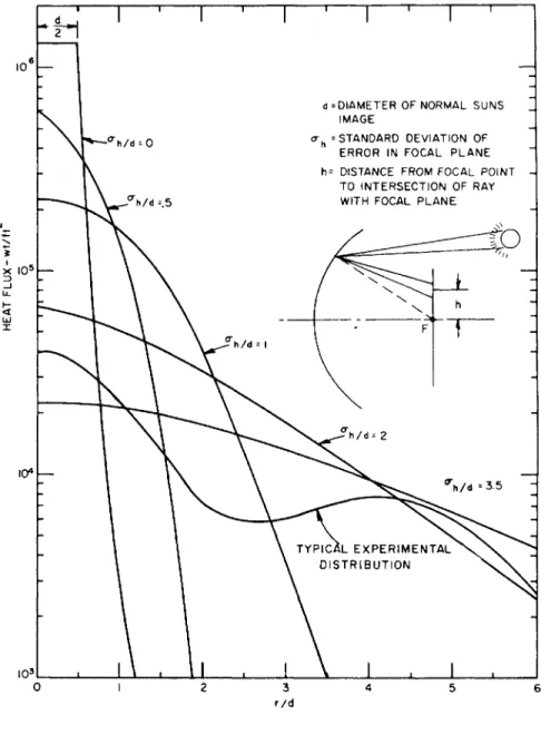
For analysis purposes, the e r r o r may be specified as follows. If the m i r r o r were perfect, incident rays parallel to the optic axis would be focussed to a common point, called the focal point. Let the plane through the focal point and normal to the optic axis be defined as the focal plane. Imperfections in the m i r r o r surface will cause the intersection of each reflected ray with the focal plane to be displaced from the focal point. For each ray, the linear (scalar) displacement of each intersection point is h. The standard deviation of such displacements is then <r, . This can be nondimensionalized by dividing by some character- istic length such as the theoretical solar image diameter, d. The quantity o\ /d is used throughout this paper to define m i r r o r geometric error.
Figure 7 shows the effect of m i r r o r surface e r r o r s on the distribution of heat flux in the m i r r o r focal plane. Even relatively small surface e r r o r s cause an appreciable
spreading of the flux. Therefore, in order to absorb most of the incoming flux, it would seem that the cavity opening should be large. However, in order to reduce re radiation losses, the cavity opening should be small. For a given m i r r o r and cavity temperature, a particular cavity opening size will be found to give maximum concentrator-absorber efficiency, or over-all heat retention within the cavity.
This effect is illustrated in Figure 8 for a particular tem- perature. Maximum concentrator absorber efficiency is presented in Figure 9 as a function of m i r r o r surface e r r o r and absorber temperature. These curves correspond to a m i r r o r with D/f = 2.3 (rim angle Θ = 60 ) which is a near- optimum value considering both efficiency and weight.
High quality searchlight m i r r o r s have values of o\ /d between 0. 5 and 1. 0 which allow them to reach black body
cavity temperatures as high as 5600 F (Ref. 7).
Concentrator Design Classifications
The development of lightweight concentrating m i r r o r s with highly accurate reflective surfaces has brought forth a whole series of new structural problems. Four broad categories of structural approaches have been considered for lightweight solar concentrators.
a. Rigid - The m i r r o r or its segments are "rigid"
in the sense that they cannot be folded or bent appreciably without damage. (Example:
Segmented rigid mirror).
b. Nonrigid - Reflector face is a thin film without appreciable stiffness. It is uniformly supported but is at all times subject to deformation if per- turbed. (Example: Inflatable collector).
c. Semirigid - Reflector face is a thin film which is supported at discrete points by a rigid backing structure. (Example: Umbrella).
d. Rigidized - Reflector face is a thin film which is pliable during launch but is made rigid in space after deployment. (Example: Foam rigidized collector).
The basic concentrator structure consists of three elements:
a. Reflector Face - A thin rigid or pliable skin of proper geometric shape and surface.
b. Backing Structure - To provide rigidity, control of shape, deployment capability and mounting
requirements.
c. Reflective Surface Coating - Applied to the face to obtain high specular reflectivity.
An important consideration is that one or more of the
structural elements must be the shape-determining element, which gives the concentrator its required surface contour.
This implies close tolerances on at least one of the above
structural elements (but not necessarily on all). The ideal structure is one in which the shape-determining element can be made from a material with excellent dimensional stability, but with good forming properties, and for which the other structural elements do not apply excessive dis- torting stresses.
Concentrator Fabrication Techniques
Structures weighing under 1 lb/ft can be produced by 2 a variety of methods. To obtain accurate structures weigh- ing . 3 lbs/ft or less and having the necessary degree of rigidity to maintain the required geometrical configuration through all phases of construction, packaging, launching, deployment and orientation appears to immediately limit the types of construction techniques possible. A detailed
discussion of m i r r o r fabrication techniques is given in Ref. 8.
Mirror fabrication is usually accomplished in four steps:
a. Forming of reflector face b. Forming of backing structure
c. Bonding of backing structure to reflector face d. Application of surface coating
In some cases these may be discrete steps; in other cases, two or more steps may be accomplished simultaneously.
Much research is now aimed at developing advanced tech- niques for concentrator fabrication. Varying degrees of
success have been achieved by several groups using different techniques. It is not yet clear which techniques may ultimately prove superior. Fabrication techniques and materials will certainly depend to some extent on
m i r r o r size and system power output, mission requirements expected service life, and other conditions. Therefore, rather than make recommendations which would undoubtedly prove premature, this paper will only attempt to list some techniques and materials which are currently being
investigated.
For rigid m i r r o r s , a critical fabrication aspect is the formation of the reflector face, which is the shape-
determining element. Among the techniques which have been investigated are:
a. Metal spinning b. S t r e t c h forming c. Explosive forming d. Androforming e. E l e c t r o f o r m i n g f. Casting or molding
In some c a s e s a sheet of highly polished m a t e r i a l ( e . g . , aluminum) is bent or s t r e t c h e d into the d e s i r e d shape. In other c a s e s , the r e f l e c t o r face is made by depositing a m e t a l or p l a s t i c skin on a highly polished m a s t e r . It is a l s o p o s - sible to m a k e fairly high quality p a r a b o l i c s u r f a c e s f r o m epoxy r e s i n s using centrifugal casting m e t h o d s . If an open cylinder containing a liquid is r o t a t e d with its axis v e r t i c a l , the free surface will take a p a r a b o l i c shape. A p l a s t i c r e s i n can be used and allowed to h a r d e n while spinning. Finally, a deposited reflective s u r f a c e can be applied. The question of the durability of p l a s t i c s in the space e n v i r o n m e n t h a s , so far limited s e r i o u s c o n s i d e r a t i o n s of t h e i r u s e f u l n e s s .
P r e f o r m e d p l a s t i c or m e t a l l i c honeycomb, p l a s t i c foams, and m e t a l l i c rib or waffle s t r u c t u r e s have r e c e i v e d p r i m e c o n s i d e r a t i o n a s backing s t r u c t u r e s for rigid m i r r o r s . The m o s t difficult p r o b l e m m a y be that of bonding the backing s t r u c t u r e to the face without causing d i s t o r t i o n . Bonding techniques u n d e r c o n s i d e r a t i o n include organic adhesive s, welding, and b r a z i n g . In the f o r m e r case d i s t o r t i o n m a y occur b e c a u s e of curing shrinkage of the adhesive bonding m a t e r i a l . Welding p r o d u c e s s o m e d i s t o r t i o n and usually ruins the reflecting quality of the skin at the weld point. With p r o p e r choice of r e f l e c t o r skin m a t e r i a l , backing s t r u c t u r e , and bonding technique, d i s t o r t i o n can be m i n i m i z e d .
In addition to d i s t o r t i o n caused during fabrication, t h e r e a r e other s t r u c t u r a l p r o b l e m s which m u s t be solved and which provide a b a s i s for c o m p a r i n g v a r i o u s fabrication techniques:
a. D i m e n s i o n a l stability of the s t r u c t u r e
b. R e s i s t a n c e to d e t e r i o r a t i o n in the space e n v i r o n m e n t c. Good t h e r m a l c h a r a c t e r i s t i c s in o r d e r to m i n i m i z e
d i s t o r t i o n following e m e r g e n c e f r o m the e a r t h ' s shadow.
It might be noted that p l a s t i c foams rate r a t h e r low in r e g a r d to all t h r e e i t e m s in the above list. P l a s t i c s in g e n e r a l rate low in r e g a r d to i t e m b.
Nonrigid, rigidized, and s e m i r i g i d s t r u c t u r e s all in- volve the development of techniques for supporting a pliable
skin or film (probably plastic) in the proper paraboloidal shape. They are differentiated by the way in which the skin is supported. The most critical element of these structures is the skin, which is the substrate for the reflecting surface and is, in some cases, the shape-determining element.
Among the most important film characteristics are:
a. Surface characteristics b. Durability
c. Tensile properties d. Sealing characteristics
General specifications cannot be made, since different
structural techniques require films with different properties.
The film must be formed in some way such that it will take a paraboloidal shape when stressed by the backing structure or the inflating gas. Among the possible ways of accomplishing this are:
a. Tailoring to shape using pie-shaped gores.
b. Stretch forming the skin using a heating mold.
The three most popular deployment and support techniques are:
a. Gas inflation
b. Rib (umbrella) structure
c. In-space rigidizing with plastic foam
Each technique has its advantages but all suffer from serious problems. Although low weight seems to make in- flatable structures attractive for short-term operation, the make-up gas required to replace that lost through meteor punctures makes this approach infeasible for long-term operation. The use of rib structures requires that the skin be supported at discrete points or lines. Thus, it is im- possible to obtain a true parabolic shape. The umbrella, for example, is composed, at best, of a series of parabolic segments. Figure 10 shows the loss in performance which results from having a finite number of segments. It can be seen that a large number of ribs is required to maintain satisfactory performance. In-space rigidizing by plastic foams is being actively investigated and seems to be an
attractive approach. However, solutions to several problems must be demonstrated before foam-rigidized m i r r o r s will be considered suitable for applications requiring high
performance.
a. Distortion of the reflector face during foam curing.
b. Lack of resistance to space environmental deterioration.
c. Distortion of the reflector face caused by flow of the viscous foam mixture prior to curing.
No matter how accurately the reflector face and backing structure are formed, the m i r r o r is useless unless it has a highly reflective surface. There are many ways of obtaining this surface depending on the materials and techniques at hand. The highest possible reflectivity is obtained by the use of vacuum deposited metallic coatings such as aluminum or silver. These are generally protected from abrasion and oxidation by the use of a vacuum-deposited transparent dielectric protective coating such as silicon monoxide.
Orientation
Because of the alignment requirements for concentrating collectors a subsystem must be provided to keep the concen- trator pointed toward the sun at all times. This orientation system consists essentially of a sensor, a servo amplifier, and an actuator.
Two types of orientation functions must be accomplished.
An initial rough orientation ability must be provided in order to allow the collector to find the sun even if it is completely mis oriented following launch. After the rough acquisition, a fine orientation system is needed to provide the directional accuracy required for adequate system performance. An indication of the orientation requirements is shown in Fig. 11.
(Ref. 9). Reorientation following emergence from the earth's shadow will probably provide the greatest in-space loads on the concentrator structure.
Environmental Degradation Effects
Many physical effects in space can potentially degrade the structural or optical performance of a solar energy collector and decrease service life. The effects of each are summarized briefly in this section.
a. Vacuum Sublimation - The low pressures in space may affect collector operation by causing evaporation of structural materials in such a way as to change the optical properties or bulk structural properties. Proper selection of materials may alleviate undesirable consequences.
All materials considered for use in space power systems must be critically examined with regard to their vapor pressures and probability of space evaporation or sublimation.
b. Electromagnetic Radiation - The collector will be bombarded by electromagnetic radiation ranging in wave- length from the far infrared to X-rays, gamma rays, and cosmic rays. The X-ray and ultraviolet portion of the
spectrum is probably the most important from the standpoint of material degradation. Plastics are particularly sensitive to these wavelengths, and care must be taken in selection of materials and in development of protective measures for preventing discoloration or deterioration.
It may be possible to protect sensitive materials by the use of surface coatings. Aluminum is a good reflector of
ultraviolet down to wavelengths of approximately 2000 A (Ref. 10).
By using a fairly thick coating it may be possible to protect plastics down to much lower wavelengths.
c. Thermal Effects - Cyclic heating caused by passage in and out of the earth's shadow may adversely affect the collector structure in two ways:
1. Thermal fatigue.
2. Distortion caused by non-uniform heating.
All-metal m i r r o r s will probably suffer less from these effects than will m i r r o r s fabricated from low thermal conductivity materials such as plastics.
d. Meteoroid Bombardment - The effects of meteoroid bombardment can only be determined by knowing the properties of meteoroids including their space density, mass and size distribution, and velocity distribution; and by having analytical or empirical description of impact phenomena. Much of our present information is based on extrapolation of astronomical observations. No reliable direct evidence has yet been ob- tained concerning the distribution or effect of meteoroid impingement. However, the degrading effect of meteoroid impingement on collector performance will probably not exceed 1 percent per year in t e r m s of loss of reflectivity.
Additional experimental and analytical data is required before a firm conclusion can be drawn. A summary of existing data is given in Ref. 11.
Gas-supported m i r r o r s , of course, suffer from a different problem: that of gas leakage caused by meteoroid punctures. Unless a self-sealing film can be devised, gas
leakage can only be o v e r c o m e by supplying e x c e s s gas to m a k e up for that which was lost through the puncture openings.
This a p p r o a c h is probably s a t i s f a c t o r y for s h o r t - t e r m operation but b e c o m e s prohibitively heavy for p e r i o d s as long as one y e a r .
e. C o r p u s c u l a r B o m b a r d m e n t - Somewhat akin to m e t e o r o i d e r o s i o n is the b o m b a r d m e n t of high e n e r g y p a r t i c l e s including c o s m i c c o r p u s c u l a r radiation, s o l a r c o r p u s c u l a r radiation, Van Allen b e l t s , and u p p e r a t m o s - p h e r i c p a r t i c l e s . The p r i m a r y effects of such r a d i a t i o n a r e :
1. D e c r e a s e in coating t h i c k n e s s due to s p u t t e r i n g or p h y s i c a l e r o s i o n .
2. A l t e r a t i o n of surface reflective p r o p e r t i e s due to p h y s i c a l d a m a g e .
3. A l t e r a t i o n of surface reflective p r o p e r t i e s due to ionization c a u s e d by incident c h a r g e d
p a r t i c l e s .
It is p o s s i b l e that these effects could cause s o m e reduction in coating t h i c k n e s s or roughening of the coating surface in such a way a s to affect surface reflectivity.
C o n c e n t r a t o r Evaluation
The effects of s t r u c t u r a l p a r a m e t e r s , m a t e r i a l s , and fabrication techniques on m i r r o r p e r f o r m a n c e can only be d e t e r m i n e d by testing a c t u a l m i r r o r s . T h r e e b a s i c types of t e s t s a r e n e c e s s a r y to get a complete p i c t u r e of m i r r o r p e r f o r m a n c e :
a. Reflectivity - The m i r r o r surface reflectivity can be m e a s u r e d d i r e c t l y using well-known optical t e c h n i q u e s . If a s m a l l flat sample of the surface finish is a v a i l a b l e , its s p e c u l a r reflectivity can be m e a s u r e d in a Spectrophoto- m e t e r as a function of wavelength.
b. G e o m e t r i c A c c u r a c y - C o r r e l a t i o n of v a r i o u s s t r u c t u r a l techniques with m i r r o r p e r f o r m a n c e r e q u i r e s d e t e r m i n a t i o n of localized g e o m e t r i c d i s t u r b a n c e s on the m i r r o r s u r f a c e . In o r d e r to a c c o m p l i s h t h i s , m o s t of the s t a n d a r d optical t e s t s m u s t be modified d r a s t i c a l l y b e c a u s e of the s h o r t m i r r o r focal lengths r e q u i r e d for e n e r g y collection s y s t e m s . A method suitable for s h o r t focal length m i r r o r s involves the use of a c o l l i m a t e d light b e a m m a s k e d in such a way as to produce a p a r a l l e l group of
narrow rays. These can then be reflected from the m i r r o r surface, and their intersections with the focal plane can be compared with ideal locations for a perfect m i r r o r . In this way, geometric angular deviations of specific points on the m i r r o r surface can be found. If the e r r o r distribution is found to be random, m i r r o r performance can be deter- mined directly from Fig. 9.
c. Thermal Performance - The overall performance of a particular m i r r o r can be found by measuring the flux distribution in the image using a cavity calorimeter.
This device consists of a water cooled cavity with a variable aperture diaphragm. By measuring the water temperature rise as a function of aperture size, a plot can be made of flux intensity in the image as a function of absorber dia- meter. Re radiation from the absorber can be calculated knowing temperature and opening size, thus allowing a simple determination of optimum cavity size for a given temperature.
There are many variations on these tests which have been suggested and used. The choice of tests depends on the suspected m i r r o r accuracy and on the equipment available for test purposes.
Conclusions
Many problems remain to be solved before ultralight- weight m i r r o r s with near-perfect surfaces will be available for long term reliable usage in high temperature space power systems. However, the rate at which these problems are being solved indicates a high degree of confidence in the ultimate practicability of efficient, lightweight solar power
systems. Collectors of low specific weight (<0. 3 lb/ft^) having efficiencies above 70 percent at absorber tempera- tures of 3000°F seem imminently feasible.
References
1. McClelland, D.H. , "Design and Development of Solar Concentrators and Their Integration into Space Power Sys- tems, "' EOS Report 410 - Final, Contract DA-04-495-506- ORD-1790, ARPA 39-59, Task 10, U.S. Army Ballistics Missile Agency, Redstone Arsenal, Alabama, 16 May I960, Fig. B-6.
2. Menetrey, W. R. , "Study and Analysis of Space Power Systems, Volume II - Thermal Energy Sources, " EOS Report 390-Final, Final Report, Contract AF33(6 16)-6791, Wright Air Development Division, Dayton, Ohio, 10 Sep- tember I960, p. II-A-10.
3. EOS Report 410-Final (See Ref. 1 above), Fig. B-13.
4. EOS Report 410-Final, Fig. 2-17.
5. EOS Report 390-Final, (See Ref. 2 above), p. II-A-83.
6. EOS Report 390-Final, Section II-A-2. 3.
7. EOS Report 390-Final, p. II-A-128.
8. EOS Report 410-Final, Section 3.
9. EOS Report 390-Final, p. II-A-129.
10. Hass, G. , Journal of the Optical Society of America, v. 45, 1955, p. 945.
11. Whipple, F. L. , "The Meteoric Risk to Space Vehicles, "
Vistas in Astronautics, Pergamon P r e s s .
NCIDENT FLUX
USEFUL ENERGY TO CONVERTER
POSSIBLE SOURCES OF ENERGY LOSS 1 Diffused reflection from mirror surface 2 Absorption by mirror surface 3 Rays which miss absorber opening 4 Reflection from absorber inner surface 5 Reradiation from absorber inner surface 6 Conduction through absorber walls
and radiation from outer surface
Fig. 1 Schematic of concentrating collector systems.
FOCAL IMAGE
''^^^tem
PARABOLOID PARABOLIC CYLINDER
SPHERE CIRCULAR CYLINDER
Fig. 2 Basic m i r r o r shapes.
0 10 20 30 40 50 60 70 80 90 RIM ANGLE-9r
00 ^ f\i ,« «* © O O O
O O _ _ _ · c\J CO ΓΟ ^ D / f
Fig. 3 Concentration efficiency and maximum concentration ratio for paraboloid m i r r o r .
144
5 0 0 0
I UJ
or £ lOOOl-
tr
H =1394 W/m
= 4425BTU/FT~HR X = ratio of useful power
withdrawn from absorber to total power intercepted
5001
CIRCULAR CYLINDER
PARABOLOID I SPHERE (6>r = 60°)
D PARABOLIC CYLINDER THEORETICAL
MAXIMUM
I i I I I I I I I I I
I05 CONCENRATRATION RATIO
i—r
TH=I050 eF
CONVERTER EFFICIENCY =13.4%
r =0.9
1 4 6 8 10 POWER OUTPUT- kilowatts
20 2 5
Fig. 5 Required collector diameter vs. electrical power output for a solar power thermopile.
146
0.14
0.12
0.10
0.08
h- x 0.06 l·-
0.04
0.02
— T = 1 2 0 0 ° F T = 2 0 0 0 ° F
CAVITY
FLAT PLATE A
HEMISPHERE
For cavity, € = | for all λ For hemisphere and flat plate,
€ -- 0.9 for solar ,λ, 0.1 for infrared λ Solar constant = I watt/in""
H«— OPERATING RANGE — * H I i ■ i I i i i i L
I 5 10 15 20 RATIO OF ABSORBER DIAMETER TO SUN*S IMAGE DIAMETER
Fig. 6 Percent loss vs. absorber size for various absorbers.
147
L 4~»J
x I 05— 3
\0*\—
I03
-°"h/d = 0
'h/d=.5
- h/d = |
d ^DIAMETER OF NORMAL SUNS IMAGE
ah = STANDARD DEVIATION OF ERROR IN FOCAL PLANE h= DISTANCE FROM FOCAL POINT
TO INTERSECTION OF RAY WITH FOCAL PLANE
Λ>
to
F
\
h
1
■ h / d = 2
rh / d =3.5
TYPICAL EXPERIMENTAL DISTRIBUTION
3 r/d
Fig. 7 Effect of m i r r o r e r r o r on flux density at focal plane of paraboloid.
<r
CAVITY TEMPERATURE = 1340° F REFLECTIVITY = 1.0
>
n
o
en -<
uy —I
m c/>
Fig. 8 Example of concentrator-absorber efficiency
VJ1 o
D/f = 2.3 rn = 1.0
1000 2000 300C
TEMPERATURE - °F
4000
>
n
CO
-<
Fig. 9 Max. collector-absorber efficiency for different m i r r o r surface e r r o r s .
SPACE POWER SYSTEMS
l dO !N30ä3d
I5I
I UK — T
0 8
v> 0.6
er 0.4
0.2 15
15
d = Sun's image
b= Cavity entrance diameter
«* Orientation Error
OPERATING REGION
'1 i ^ '
0 2 4 6 8 10 12 14 16 RATIO OF CAVITY ENTRANCE DIAMETER TO SUN'S IMAGE DIAMETER-b/d
Fig. 11 Example of percent loss incurred by orientation e r r o r .