STATUS OF SOLAR ENERGY COLLECTOR TECHNOLOGY Atwood R. Heath Jr.*
NASA Langley Research Center, Hampton, Va.
Abstract
A survey has been made of the state of the art of solar energy collector development. Various types of collector con- cepts along with methods and materials of construction are dis- cussed. The concentrating ability and efficiency are presented for several collectors which have been constructed to date.
For the various collectors, analyses are made with regard to such factors as: unit weight, specific power, launch package volume, and operating temperature of the energy conversion device.
Introduction
A survey has been made of organizations known to be active in the solar energy collector field in order to determine the status of the technology at this time. The selected method of conversion of solar energy to electricity, with the attendant different temperature requirements, governs to a large extent the line of approach to lightweight concentrator concept and construction taken by any organization. These different lines of approach result in a varied assortment of collectors that range from very lightweight mirrors, such as inflatable plastic models, to relatively heavy one-piece mirrors. With such diverse activity in the field, a summary of the properties of the various types is needed to indicate the overall picture of the accomplishments to date.
Specifically, a summary is made of the efficiency, concen- trating ability, unit weight, and packaged volume of solar energy collectors fabricated to date.
Presented at the ARS Space Power Systems Conference, Santa Monica, California, September 25-28, 1962.
^"Aero-Space Engineer.
Description of Fabricated Collectors
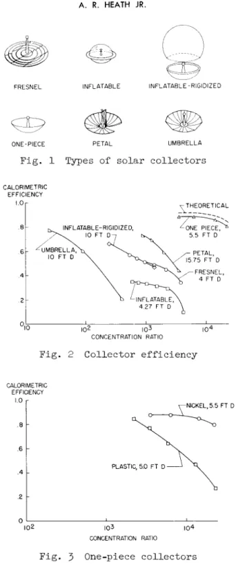
Figure 1 presents sketches of six different concepts of lightweight solar energy collectors. These six concepts are not the only ones being considered, but they are the concepts that have been developed to a point where quantitative data on their capabilities exist. Examples of the six types are listed in Table 1 with some of their pertinent characteristics. For two types, additional collectors fabricated by different methods and materials of construction also are presen+ed. A brief description of each of the types with some details of the materials and methods of fabrication follows.
The Fresnel collector1 is shown in Fig. 1, and the folding arrangement, which consists of four hinged panels, is indi- cated. The Fresnel surface is made by electroforming nickel on a steel master that has been machined and polished. The Fresnel electroform then is bonded to an electroformed stiff- ening structure.
Shown next on Fig. 1 is one form of an inflatable-type col- lector. 1 The collector is pressurized and is formed of an aluminized Mylar paraboloid and a clear Mylar front cover. An inflated torus also made of Mylar is attached to the outside of the collector at the junction of the reflecting surface and the front cover. The reflective surface is stretch-formed during fabrication.
A sketch of the inflatable-rigidized collectors5 is shown next. Basically, this collector is an aluminized plastic par- aboloid that is rigid!zed in space by the application of a foamed plastic to the back of the collector. The collector that is discussed in this paper is a feasibility model for use in ground tests.
The next sketch shows a one-piece collector. Л One method of fabricating this type of collector consists of electroformin a thin dish of nickel on an appropriate master. The dish then is stiffened by the addition of an electroformed torus to the periphery of the dish. Another method of one-piece collector construction uses a honeycomb sandwich that consists of a cast epoxy plastic-reflecting surface bonded to an aluminum honey- comb, which is in turn backed up by a plastic Fiberglas panel.
The reflective face can be cast on any suitable convex master.
Several collectors have been made by this method of construc- tion. 8 Several other one-piece collectors have been con- structed by methods such as spin-casting of plastic9 and hydro- forming of aluminum,10 but complete quantitative data on the capabilities of these collectors are not available.
Next is shown a sketch of a petal collector. There are sev- eral variations of this type, hut in all cases the collector consists of a huh with attached petals that fold up to form a compact package for launching. A deploying system consisting of springs, cables, or mechanical linkages is used to open these devices. Several collectors of this type have been built, and different methods have been used in the construc- tion of the petals for each. One collector^ had petals of electroformed nickel, monocoque construction. Two others had petals of honeycomb sandwich that consisted of an aluminum reflecting face, honeycomb, and back; one was a 32.2-ft-diam model,9 and the other was a 15*75-ft-diam modelД1 Anotherl2 had petals formed of a thin aluminum face that was stiffened by a light aluminum lattice truss spot welded to the back.
The last sketch shows a typical umbrella collector.^3 This collector consists of an aluminized Mylar covering stretched over metal ribs. This collector also had an operational pneu- matic erecting mechanism.
Collector Efficiency
The important feature of a collector is the ability to col- lect the solar radiation efficiently and to provide the proper degree of concentration of the radiation commensurate with the ability of the conversion system to use the heat. The data presented herein were obtained by means of cold calorimeters that are essentially heat absorbers that operate at slightly above ambient temperatures. At these temperatures, reradia- tion from the calorimeter is very small, and the measured effi- ciency is only a function of the collector geometry and
reflectivity.
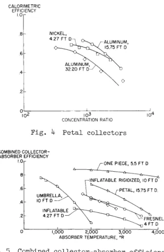
Figure 2 shows the efficiency as a function of concentration ratio for a representative group of collectors. The collector having the highest efficiency and concentration ratio has been chosen where several collectors of a specific type exist. A cavity calorimeter was used in all instances but one. The umbrella was tested with a spherical calorimeter because the collector rim angle was 90°, thus making the cavity type unsuitable. The efficiency is based on the projected net reflective area. The concentration ratio is based on the ratio of the projected net reflective area to the calorimeter aper- ture area. For the umbrella collector, the calorimeter aper- ture area is replaced by the surface area of the spherical receiver. All of the collectors had a reflective surface of vapor-deposited aluminum.
As might be expected, the one-piece electroformed nickel collectoré is superior to the expandable collectors in geometry as indicated by the higher efficiencies at the higher concen- tration ratios. Also included in Fig. 2 is the theoretical curve for this collector calculated for a reflectivity of 0.91»
It can be seen that the data for this collector approach the theoretical curve very closely, which indicates that the master is of good quality and the reproduction process is very
faithful.
The next most efficient collector at higher concentration ratios is the 15.75-ft-diam aluminum honeycomb petal model. A calculated efficiency curve based on the measured geometry of the petals was madell and was found to be about 0.10 higher than the measured values of efficiency. This discrepancy is thought to be due to inaccuracies in the measurement of the petal geometry plus convective heat losses from the calorimeter cavity due to wind.
The inflatable-rigidized and Fresnel collectors fall very close together on Fig. 2. Planet photographs made with the Fresnel collector1 indicated that the outer edges of the ser- rations deviated from a conical shape due to difficulties in polishing the steel master. Also, deviations in geometry due to the effects of the backing structure bond to the reflective face were noted. One further cause of low efficiencies for this collector is the inherent shadowing problem of the Fresnel mirror. The inherent shadow area is 15$ of the total area;
thus, if this 15$ were removed from the total reflective area, the efficiency calculated on the basis of the reduced area would be 0.6l instead of 0.51 at a concentration ratio of 1000.
The inflatable-rigidized collector has been tested with a cal- orimeter that effectively had only two different apertures so the exact variation of efficiency with concentration ratio is difficult to determine. An "orange peel" effect was observed in the reflective surface of this collector, but no assessment of adverse effects, if any, could be made. Lower efficiencies also could result from the use of commercial aluminized Mylar, which has a reflectivity of only about O.83.
The inflatable paraboloidal concentrator gave relatively low estimated efficiencies in the concentration ratio range near 1000. The low efficiencies were attributed to the large trans- mission and reflectance losses from the transparent front face as well as reflectance and transmission losses of the
reflecting surface. The relatively flat curve of efficiency with concentration ratio indicates that the geometry of the
reflecting paraboloid is good up to concentration ratios of about 25OO, where a sharp decrease in efficiency occurs.
The concentrating ability of the umbrella collector is much below the ability of any of the other collectors shown in Fig. 2. The main problem with this type of collector concerns the shape of the reflecting surface gores between ribs. The gores have a tendency to take a shape that is nonparaboloidal;
thus, a lower concentration of the sunTs rays results. The number of ribs used to form the collector determines to some extent the concentrating ability, with a greater number of ribs giving better concentration. A spherical absorber was used for this collector; therefore, it is difficult to compare this col- lector to the others of Fig. 2 because cavity absorbers were used.
Figure 3 shows the efficiency-concentration ratio curves of two one-piece collectors, the electroformed nickelé shown pre- viously on Fig. 2 and a cast plastic-aluminum honeycomb model.°
The geometry of the plastic collector is not as good as that of the electroformed collector, as indicated by the steeper slope of the efficiency curve. This is not surprising, in view of the fact that two more replication steps were required to arrive at the plastic collector than were used to get the nickel collector. The latter was electroformed on a glass searchlight master, whereas the former was cast on a plastic master that had, in turn, been cast from a metal searchlight mirror of uncertain quality.
Figure k shows the efficiency curves of three petal collec- tors, one, the 15.75-ft-diam model,^ was shown on Fig. 2, and the others are the electroformed nickel collectorl and the 32.2-ft-diam stretch-formed, aluminum-honeycomb collector.9 All three collectors are in the same general range of effi-
ciency and concentration ratio. The electroformed collector had petals with a degraded reflective surface due to unsatis- factory protective coatings. The efficiencies shown on Fig. K would be about 0.12 higher if better coatings had been used.
This would give an efficiency of O.80 at a concentration ratio of 600. The data for the 32.2-ft-diam collector are for one petal only and do not reflect the problems associated with petal alinement. The petal showed honeycomb markoff and roll marks. The roll marks were removed by a mechanical polish, but diffusion of light from the polish scratches was still evident.
An epoxy layer over the polished aluminum has been effective in increasing the reflectivity, and the markoff has since been reduced by better control of the bonding agent used. No cal- orimetric tests have been made since the improvements to the petals were completed. The stretched-formed lattice-truss
collector^ was tested only by optical ray-tracing methods, but a general idea of the quality of this collector can be obtained by comparison with two other collectors that were tested by the same method as well as by calorimetry. If a reflectivity of 0.86 were assumed, the collector efficiency would fall slightly below the data for the electroformed collector.
Collector-Absorber Operating Temperatures
The curves of Fig. 2 indicate only the efficiencies of the collectors, that is, no reradiation occurs from the calorime- ter. A collector must be combined with an absorber that radi- ates at its operating temperature to find the temperature capa- bility of the collector. For purposes of analysis, a cavity absorber is assumed with an absorptivity and emissivity of 1.00.
The solar constant that affects the reradiation term is assumed to be 130 w/ft2. The efficiency data of Fig. 2 are used in combination with reradiation losses of the assumed absorber to obtain the efficiencies of the combinations as a function of temperature as is shown in Fig. 5« At a given temperature, the efficiency shown is the maximum obtainable and represents a specific concentration ratio. It is seen that, if a thermi- onic conversion system with temperatures near 4000°R is
required, only the electroformed one-piece mirrors are capable of efficient operation at the present time. All of the expand- able collectors are relatively inefficient even at temperatures around 2000°R.
Collector Weights
The unit weights of the collectors discussed so far as well as some that were built but have not been evaluated completely are shown in Fig. 6.
The inflatable-rigidized collector has a very high unit weight of 3.82 psf. This collector was a ground test model and was not intended to represent flight hardware weight. An estimated weight curve made by the manufacturer for a flight article that could be made at the present time is shown. The unit weight approaches 0.2 psf for collectors with diameters above 30 ft.
The unit weights of the one-piece collectors vary from 0 Л 0 to slightly over 1.00 psf. The collectors with unit weights of 0.4o and 0.70 psf had definite problems with geometry, and so it can be expected that one-piece collectors with good geometry will weigh roughly 0.9 to 1.0 psf for construction by methods discussed so far.
The Fresnel mirror has a unit weight of 0.46 psf, which is about half that of the one-piece collectors. Most of the petal model weights are about half that of the Fresnel.
Roughly, it carl be expected that the furlable type can be made to weigh about 0.20 psf for petals alone for diameters at least to 32 ft. The addition of hubs and erecting mechanisms will add to this unit weight; for example, these components weighed 0.07 psf for the 32.2-ft-diam collector.9
The umbrella collectors have unit weights of about 0.11 psf, which includes the ribs, hubs, and plastic covering. Calcula- tions in reference 13 indicate that this weight will increase with collector diameter, as shown in Fig. 6. The 10-ft-diam collector was equipped with a pneumatically operated unfurling mechanism, which was powerful enough to operate a 50-ft-diam
collector. Based on the larger diameter, the unit weight of the mechanism would only be 0.01 psf. Therefore, the weight of the unfurling mechanism could be negligible for large- diameter collectors.
The lowest unit weight of any collector shown is 0.03 psf for the inflatable model. This weight is based on the use of 1-mil plastic and does not include any inflation gear. The low unit weight of this collector makes it of interest, in spite of the many obvious problems such as environmental limitations asso-
ciated with the concept.
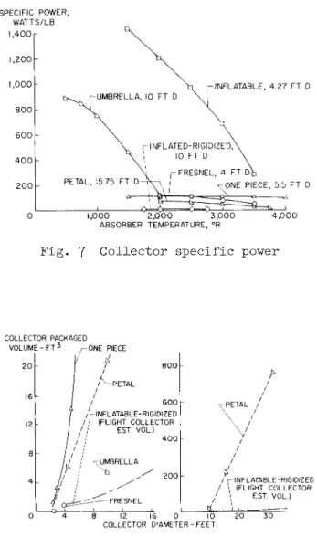
Figure 7 shows the specific powers of the collectors shown in Fig. 5- The combined collector-absorber efficiencies of Fig. 5 were used with the unit weights of the various collec- tors and a solar constant of I30 w/ft^ to obtain the values shown. The inflatable collector delivers the most heat per pound for absorber temperatures below about 3500° F due to the extremely low unit weight of the collector. On the other hand, the very efficient one-piece electroformed collector has a relatively low value of specific power due to its heavier weight. However, when comparing these two collectors at the same value of specific power, the inflatable would be many times the size of the one-piece collector for power systems of the same output. The inflatable-rigidized collector has a very low specific power because the weight of the ground test model was used. The petal collector shown in Fig. 7 n a s a relatively low value of specific power because basically it was to be used as a ground test model also and thus was fairly heavy.
The efficiencies for this collector were shown previously on Fig. k with two other collectors, the electroformed nickel petals-^- and the 32.2-ft-diam aluminum-honeycomb petals.9 Both of these latter collectors have values of specific power about
five times greater than the power for the collector shown, due to much lower specific weights.
Packaged Volumes
The packaged volumes of the various types of collectors are shown in Fig. 8. It has been assumed that each paraboloidal collector will fit into a cylindrical shape and that the folded Fresnel collector will fit into a rectangular prism.
The one-piece collectors have the highest volumes for a given diameter, because it has been assumed that no folding would be practical. Of course the limiting factor for one-piece models is the launch vehicle diameter, and the packaged volume as determined could be relatively meaningless.
The petal collectors are the next highest in volume, which runs to over 700 ft3 for a 32.2-ft-diam collector. Minor reductions in the volume of this type of collector might be made; however, no radical reduction in volume is expected.
The umbrella collector has a fairly low volume at least for the 10-ft model. The collector can be packaged in a long slender cylinder, which might present some problems. Collec- tors have been proposed in which the ribs would have more than one folding joint. This scheme would, no doubt, give a package that is more easily managed.
The Fresnel collector has a very low volume in the l·-ft model, but the inflatable-rigidized collector has the most
favorable packaged volume of any collector shown, especially in the larger sizes. The curves show estimated values of vol- ume that can be achieved presently.
No volume is given for the inflatable collector, but it seems possible that this collector can be packaged as effi- ciently as the inflatable-rigidized collector.
Concluding Remarks
In summary, a survey of the state of the art of solar energy collector technology has been made, and a brief discussion of the various areas of accomplishment follows.
One-piece electroformed nickel collectors that closely approach the theoretical concentrating ability and efficiency have been fabricated. The unit weights of these collectors fall in the range of 0.90 to 1.00 psf. The delivered energy
per pound of collector weight is relatively low for these col- lectors , hut they are capable of attaining higher absorber temperatures (greater than 4000°R) than lighter collectors.
Other types of collectors such as petal, Fresnel, inflatable, and inflatable-rigid!zed fall in the concentration range of about 500 to 5OOO, which would make them suitable for lower temperature requirements (around 2000°R). The inflatable type has a very higih ratio of delivered energy to collector weight
(1200 w/lb at 2000°R based on plastic weight only), whereas the petal models yield around 375 w/lb, which is about three times that of the one-piece collectors. The unit weights for the various types range from 0.03 psf for the inflatable to 0 Л 6 psf for the Fresnel.
The umbrella collector has a very low concentrating ability, which is in the range of 25 to ^00. The temperature range for this collector thus falls around 1000°R. At this temperature, the collector yields about 750 w/lb due to the low unit weight.
References
1 Springer, L.M., "Study, design, and fabrication of solar energy concentrator models," EOS Rept. 1577-Final, Electro- Optical Systems, Inc. (September 1961).
2 "Solar concentrator development and evaluation program,"
GER-10084, Vols. I and II, Goodyear Aircraft Corp.
(January 1961).
3 "Second quarterly progress report preprototype solar collector 15-kw solar mechanical power-generation system,"
GER-IO252, SI, Goodyear Aircraft Corp. (August 22, 1961).
^ Tanenhaus, A.M., "Inflated-rigidized paraboloidal solar energy concentrator evaluation," GER-10295; Goodyear Aircraft Corp. (July 20, 1961),
5 "Quarterly progress reports of 15-kw development program,"
Sundstrand Repts. CDRD-6l:5008, CDRD-6l:5011, CDRD-6l:501^, CDRD-62:5015, CDRD-62:50l6, CDRD-62:5017 (196I-I962).
6 Menetrey, W.R., "Solar energy thermionic conversion system," EOS Rept. 1850-Final, Electro-Optical Systems, Inc.
(January 19б2).
7 Pichel, M.A., "Research and development techniques for fabrication of solar concentrators/' EOS Rept. 1587-Final, Electro-Optical Systems, Inc. (December 1961).
8 Gillette, R.B. and Snyder, H.E., "Development and testing of lightweight solar concentrators," Doc. D2-10107.? Boeing Airplane Co. (June I96I; revised December 1961).
9 Castle, C.H., "Solar concentrator development status at TRW," Tech. Memo. 33^5-68, Tapco Div., Thompson-Ramo-
Wooldridge, Inc. (February 1962).
10 Ferrara, J.R., "A solar thermoelectric generator system study," Aeronaut. Systems Div. TR 61-315, U.S. Air Force (November 1961).
1 1 Cuthbert, D.J., Purdy, D.L., Williams, E.W., Ruff, J.A., Kerr, D.L., Flanigan, W.G., Luck, R., Jr., Jones, D., and Baum, E., "Solar thermionic electrical power system," Tech.
Doc. Rept. ASD-TDR-62-9^, U.S. Air Force (March 1962).
12 Sandborn, D.S., "The development of deployable solar concentrators for space power," Ryan Aerospace; also Soc.
Automotive Engrs. (October 1961).
13 Nowlin, W.D. and Benson, H.E., "Study of an erectable paraboloidal solar concentrator for generation of spacecraft auxiliary power," NASA TN D-I368 (1962).
as as
Type
F r e s n e l Inflatable Inflatable- rigidized One piece
Petal
Umbrella
Method of construction Electroformed Stretch formed
. . . Electroformed Cast plastic Electroformed Stretch formed Welded lattice truss
Stretch formed 60 Al ribs
Material
Nickel Mylar Mylar-
foam Nickel Epoxy- Fiberglas
Nickel Aluminum honeycomb Aluminum Aluminum honeycomb
Mylar
Rim angle,
deg 40.00 53.13 60.OO 61.50 60.50 53.13 45.OO
45.OO 52.00 90.00
Diam, ft
4.00 4.27 10.00 5.5O 5.OO 4.27 15.75
10.00 32.20 10.00
Net projected reflective area, ft2 i
12.10 I3.OO 76.OO 19.77 I8.69 I3.OO I73.8O
75.97 745.OO 77.8I
Reflective material Aluminum Aluminum Aluminum Aluminum Aluminum Aluminum Aluminum
Aluminum Aluminum Aluminum
Measured reflectivity
O.85
• . . . O.89 - 0.90 0.755 ± 0.1
. . . 0.86
.. . .
0.85 0.83
Unit wt, psf
0.46 О.ОЗ esta
З.82 O.96 O.94 0.20-0.40b
1.00
0.29Ъ 0.18Ъ 0.11C
Ref.
1 1 2-5
6 8 1 11
12 9 13
a Mylar only.
"b Petals only.
FRESNEL INFLATABLE INFLATABLE-RIGIDIZED
ONE-PIECE PETAL UMBRELLA
Fig. 1 Types of solar collectors
CALORIMETRIC EFFICIENCY
1.0
FRESNEL, 4 FT D
I02 I 03 I 04
CONCENTRATION RATIO
Fig. 2 Collector efficiency
CALORIMETRIC EFFICIENCY
1.0 r
•6 h
102
NICKEL, 5.5 FT D
PLASTIC, 5.0 FT D
I03
CONCENTRATION RATIO I 04
Fig. 3 One-piece collectors
CALORIMETRIC EFFICIENCY
I.Or
10*
ALUMINUM 32.20 FT D
I 03 CONCENTRATION RATIO
Fig. k Petal collectors
COMBINED COLLECTOR- ABSORBER EFFICIENCY
1.0 ONE PIECE, 5.5 FT D
INFLATABLE RIGIDIZED, 10 FT D PETAL, 15.75 FT D.
1,000 2,000 3,000 ABSORBER TEMPERATURE, °R 4,000
Fig. 5 Combined collector-absorber efficiencies
A 3.82 LB/FT2 UNIT WEIGHT -
LB/FT2 l.0r A
COLLECTOR O FRESNEL
□ INFLATABLE
<0 INFLATABLE-RIGIDIZED Д ONE PIECE
fc. PETAL Ь UMBRELLA
-INFLATABLE-RIGIDIZED (FLIGHT COLLECTOR EST. WT.)
UMBRELLA EST. WT-
8 12 16 20 24 28 32 COLLECTOR DIAMETER-FT
Fig. 6 Collector unit weight
SPECIFIC POWER, WATTS/LB 1,400
INFLATABLE, 4.27 FT D
FRESNEL, 4 FT D t
ONE PIECE, 5.5 FT D
1,000 2,000 3,000 ABSORBER TEMPERATURE, °R
4 , 0 0 0
F i g . 7 C o l l e c t o r s p e c i f i c power
COLLECTOR PACKAGED V O L U M E - F T3 ^-ONE PIECE
INFLATABLE-RIGIDIZED / / (FLIGHT COLLECTOR
EST VOL.) 4 0 0
-PETAL /
/ rINFLATABLE-RIGIDIZED / \ (FLIGHT COLLECTOR
1 \ EST. VOL.)
12 16 0 10 2 0 3 0 COLLECTOR DIAMETER-FEET
Fig. 8 Collector packaged volume
![BasedontheEUROSTATdatabase[ ],theshareofenergyproducedbyrenewablesources sustainableenergy.AccordingtoWolsink[ ],policymakersandresearcherspresentrenewablesasasolutiontoenvironmentalproblems,particularlyglobalissueslinkedtofossilfuelsandnuclearpower.Botht](data:image/gif;base64,R0lGODlhAQABAIAAAP///wAAACH5BAEAAAAALAAAAAABAAEAAAICRAEAOw==)