Components of building integrated solar collectors
István Fekete1* and István Farkas2
1Department of Technical Engineering, College of Szolnok Tiszaligeti sétány 14., Szolnok, H-5000 Hungary
Email: feketei@szolf.hu
2Department of Physics and Process Control, Szent István University Páter K. u. 1., Gödöll , H-2103 Hungary
*Corresponding author, Email: Farkas.Istvan@gek.szie.hu
Abstract
This paper is dealing with the development of a new type of shell-structured solar collectors for the heat exploitation of the solar energy and to define its thermal efficiency. In designing of the shell- structured collector bodies it was used a proper combination of the traditional and new materials. It has been form a new, profitable, small investment claiming solar collector. Finally it has been developed an easy-to-install equipment, which is expected to be really effective in the summer period along with impoving the efficiency. Energy balance of the collector including the influencing factors especially the radiation and convection are expressed by their heat loss coefficients. The temperature distribution on the collector surface was validated by an infrared camera recording. During the modelling and simulation the main consideration was given to the efficiency issues. Certain modification on the equipment is needed for further improvements, based on additional improving concepts and more accurate measurement, in order to improve heat transfer of the collector body.
Keywords: Irradiation, temperature distribution, thermal efficiency, structure design.
1. Introduction
The proportion of use of the renewing energy resources in the meeting energy-demands is only a few percent at the moment in our country. To increase this proportion is of high importance and significance within the entire energy consumption from many points of view (Fekete, 2002). There are significant subsidies to modernize the energy consumption, primarily for installation of solar collectors, which could help the structural reform of the energy supply. The design of the present heat exploitation solar collectors has special structure in many cases, it uses special material, therefore the specific expenses of this type of energy production can be considered high (Farkas, 2000). There are possibilities in two main directions in development of collectors:
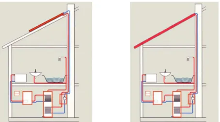
1) The first is linked to structural changes of materials that are recently used roof construction meaning that the architectural design would not change, but the required surface operates as solar collector, as it can be seen in Fig. 1.
2) The other way is an appropriate development, junction of a cheap plastic, water chamber, UV resistant PVC collector bodys to the heating- and hot water providing systems.
For the justification of the theoretical calculatios the necessary tests and inspections on equipments of locally design were performed. The required measurement site has been designed in order to establish individual and comparative measuring possibilities of the different kinds of collector bodys, as well as fixing possibility of specific weather parameters.
Fig. 1. System with traditional design and the system with new design 2. Energy balance of solar collectors
The geographical location of Hungary is appropriate for the use of solar energy. The quantity of the available solar energy reaches a rather high level in this region, similarly to the energy, which may be produced by the collector bodys (see Fig. 2).
Mez túr 1340 1308
1278 1250
<1200
Mez túr 2150 2100 2050 2000
1950
<1950
Fig. 2. The annual sum of the solar radiation (kWh/m2, year) and the number of the sunny hours (h/year)
The roof integrated collectors convert the solar irradiance to heat energy with some losses, details can be seen on Fig. 3. Losses can be divided into optical and heat losses.
2
7
3 6
4 1
5
7 7
Major energy factors:
1. Direct solar radiation 2. Diffused solar radiation 3. Reflection
4. Losses from convection 5. Wind, rain, snow, convection 6. Conduction losses
7. Useful output
Fig. 3. Energy balance of solar collectors
The optical loss is the reflection and absorption of the solar radiation of the glass cover and the absorber plate and it is not depending on the temperature of the collector. The heat loss is depending on the temperature differences between the collector and the ambient air. Effect of the solar radiation the absorber plate warmiung up by radiation, convection and heat transfer causes the heat loss.
Efficiency of a thermal equipment determines the ratio between the inlet and used heats. The collectors ”fuel” is the electromagnet radiation of the Sun. Hence, the efficiency of solar collectors expressis the rate of the used heat energy of the collector and the incoming solar radiation. The losses and the efficiency of the collector are significantly influence by the momentary ambient temperature and incoming solar radiation. Therefore the efficiency of the collectors is to be given by graphs and not by mathematical equations.
At the same time absorption and emissivity of different materials and surfaces under a certain temperature are varying. The absorbed radiation converted into heat. A lot of materials has the same absorption and emissivity, such as grey and black surfaces. Performance of the solar thermal system higher when the reflectivity is low and the absorption is high. So, the construction of the absorber must be the best absorption and low heat loss under operate. As conclusdion it can be say that the characteristic of the best occlusive materials that solid, opaque and low reflectivity capability (Medved, 2003).
3. Mathematical model of solar collectors
The thermal behaviour of building integrated collector elements was analysed by simulation. In the course of the task the goal was to increase and optimize the thermal efficiency of the integrated shell-structured collector bodies and optimize. There is opportunity to reach the technologically maximum of efficiency ( ) by changing the structure and substance construction of collectors (Kendrick, C., 2009). Influenced factors are the following: intesity (I), ambient temperature (Tw), medium temperature of flowing working fluid (Tm), inlet temperature of working fluid to the collector (Tin), outlet temperature of working fluid from the collector (Tout). It is need to measure the warming of the working fluid to calculate the efficiency of collector according to working volume rate.
In the course of the experiments carried out the influence of the solar radiation and the temperature rise concerning to the thermal efficiency are to be studied intensively.
The temperature of the absorper plate is depending on the intensity and the size of the absorber surface (Pisello, 2011). Based on the differential equation of the heat transfer the energy is conveyed section to section depending on the volume rate ai it can be seen on Fig. 4.
Notations in the figures are the following:
Tcs - temperature of tile surface, Acs - tile surface,
Tm0 - inlet temperature of working fluid, Tm1 - outlet temperature of working fluid, Am - volume rate cross-section of working fluid, dVm - volume of working fluid,
w, h, dl - geometric parameters of tile, m - mass flow of the working fluid.
Tw
I
m Tm0
Tm1
dVm Am Acs
Tcs
Fig. 4. Structure and heat balance of absorber element
For that modelling purpose the following equation are to be used where the heat transfer to the environment through conduction, radiation and convection are expressed by the k1 and k2 heat loss coefficients:
T) f(I,
!! " , (1)
I T2 k2 I T k1
!0
!! " " " " . (2)
The variables and the equations for the Matlab coded simulations (shown in Fig. 5) are as follows:
Fig. 5. Model of the tile element with Matlab realization
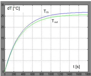
In calculating the temperature distribution in the shell-structured tiles the results of the simulations are shown in Fig. 6. In the exeperiment the lenght of the pipe built in tile is 2,5 m, radiation 600 W/m2, air temperature 20 °C, temperature of the constant volume rate inlet working fluid 18 °C.
Tout
t [s]
Fig. 6. Simulation results of experiment No 1
During the simulation results it can be determined the most influencing parameters of the system, which can be used for developing o new scollector structure. In Table 1 the most influencing parameters are indicated in in grey colour.
Table 1. The list of influencing parameters
dl lenght of tube:
optimization of heat transfer, number of serial elements
dv diameter of tube,
optimization of diameter, dv< h, w; strength:
dvmax~ h/2, w/2 Vv=((dv^2*pi)/4)*dl; volume of tube Av=dv*pi*dl; surface of tube cv=4196; specific heat of water
vv flow rate of water: pump optimization rov=1000; density of water
dm=vv*((dv^2*pi)/4)*rov; mass flow rate of water
Making use of the simulation results during the preparation the experimental elements can be optimized. It is an important part in the final geometric design. It could be determined the diameter, length, section size, volume rate, etc.
4. Construction of shell-structured collectors
Based on the simulation and modeling a complete system was planned and built for measuring.
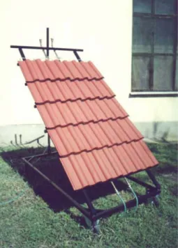
This system is available to use comparative experimental, it can be improve or enlarge it. The angle of the incoming radiation is changing by the seasons and period of the days that is why important to set into the incoming radiation direction. The tilt angle of the equipment (30°-45°) and the azimuth angle (0#-360#) are adjustable. Figs 7-8 show the surface of the collector and a tile element design.
Fig. 7. Surface of the collector (~2 m2) Fig. 8. The tile element design
The solar collector, by itself, doesn't guarantee optimal operation of a equipment working with solar energy; much more depends on the complete system solution (Fig. 9).
The two-circle (solar and HMV) development provides adequate separation and better controlling.
The connection between the two circles is provided by the external heat exchanger. The circulation is maintained by two-step pumps. The connection is worked out via copper pipes.
Fig. 9. The complete system solution
1. Collector 2. Solar detector 3. Collector detector 4. Air valve 5. Thermometer 6. Manometer 7.
Pump 8. Safety valve 9. Expansion tank 10. Quantity measuring device 11. Heat exchanger 12.
Filling-evacuating tap 13. Buffer tank 14. Control electronics
The heat-technological phasing of the system is assured by the control unit, which was recommended especially for the sun collectors. The controller has 10 detector inputs and 5 conducted outputs, indicating operation status, breakdown and program-mode. Storage of the received heat energy is provided by a 300 1 buffer tank, which provides additional applications.
The ordinary built-in instruments and the safety fittings help the safe running.
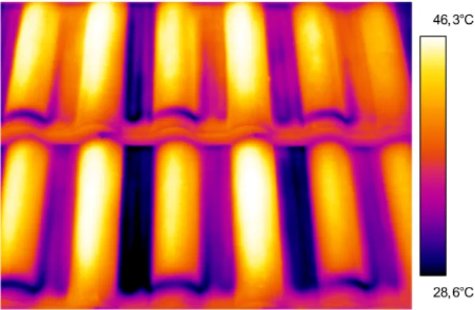
In Fig. 10 the infrared camera recording shows the temperature distribution on the surface. In the bottom of tile it can be seen that the outlet fluid still cold. In top of the figure a constant, controlled state can be observed, where the temperature of the outlet fluid and the surface are nearly the same.
28, 6°C 46, 3°C
Fig. 10. Temperature distribution of the tile collector
If the difference between the collector and the environment’s temperature is zero, then the collector doesn’t radiate heat to the environment, therefore the efficacy reaches the maximum value, we call it optical efficacy 0. The comparative values and heat-loss factors of the optical efficiency (efficacy) are the following: 0 = 81%; k1 = 3,78 W/m2K; k2 = 0,013 W/m2K.
The characteristic curve of the collector efficiency is drawn in Fig. 11.
Fig. 11. Collector efficiency curve
Certain modification on the equipment is needed for further improvements, based on additional improving concepts in order to achieve more accurate measurement, as well as to improve heat transfer of the collector body. Furthermore aim is to develop an easy-to-install equipment, which is expected to be really effective in the summer period along with considerable efficiency increase, when the temperature of the ambient air is almost equal with the temperature of the inlet water. At colder external temperature the collected solar energy will be less, than heat-loss of the collector body. Concerning the design aspect several trials has been performed. It has also been developed
solar tiles that integrate right into the roof. The unique design making themselves almost invisible.
The tiles can also be linked easily together (Designboom, 2012).
5. Conclusions
Based on the experimentals a question has arrised that the current used equation of the efficiency of the solar collectors is suitable for the calculation or not. Medium temperature of the collector used in equation not reflected the real efficiency. To increase the energy use and to improve the control of a solar thermal system it is important to determine the effect of the inside temperature distribution and the coupling the collectors.
A further question of extending the economical operating time of the collectors. The collectors initial and shutdown operation time depending on the type of the colector, circulation system and coordination between the elements. It is supposed that a non-water based fluid has an effect on the operating time and on the economical operation. Advantage of the combined systems would also make a sense to spread of the economically operating collectors.
Acknowledgement
This work was supported/subsidized by TÁMOP-4.2.2.B-10/1 "Development of a complex educational assistance/support system for talented students and prospective researchers at the Szent István University" project.
References
[1] Fekete, I. (2002): Thermic efficacy research of the shell-structured collector bodies integrable into architectural structures, Proceedings of the Third Conference on Mechanical Engineering, Vol. 1., Budapest, pp. 37-41.
[2] Farkas, I. (2003): A combined solar farm energy/technology system in Hungary, Hungarian Agricultural Research, Vol. 9, No. 2, June 2000, p. 18-21.
[3] Kendrick, C. (2009): Metal roofing on residential buildings in Europe: A dynamic thermal simulation study, Report 090903ECC, Oxford, September 2009.
[4] Medved S., Arkar C., Cerne B. (2003): A large-panel unglazed roof-integrated liquid solar collector – energy and economic evaluation, Solar Energy, Vol. 77, No. 6, pp. 455-467.
[5] Pisello, A., Rossi, F., Cotana, F. (2011): Increasing roof albedo: a retrofitting strategy for buildings and environment, 48° Convegno Internazionale AiCARR Baveno, Lago Maggiore 22-23 settembre 2011.
[6] Designboom, Solar roof tiles (2012),
http://www.designboom.com/weblog/cat/16/view/7265/solar-roof-tiles.html, 01. 04. 2012.