Electrography and Electro-Spot Testing
B Y
H. W. H E R M A N C E A N D Η. V. WADLOW Bell Telephone Laboratories, Inc., New York, New York
CONTENTS
Page
1. Introduction 156 1.1. Surface Analysis 156
1.2. Chemical Contact Printing 157 1.3. Electrolytic Transfer 158 1.4. Historical Review 159 2. Equipment, Materials, and Manipulative Techniques 160
2.1. Basic Technique of Electro-Transfer 160 2.2. Cell Arrangements and Accessories 161 2.3. Current Supply and Control 167
2.4. Transfer Media 169 2.5. Preparation of the Specimen 172
2.6. Standard Specimen Block 173 2.7. The Technique of the Electro-Transfer 175
3. Electrolytes, Reagents, and Developing Processes 180
3.1. Production of the Image 180
3.2. The Electrolyte 182 3.3. Recognition of the Transferred Products 185
3.3.1. Examination of the Undeveloped Print 185
3.3.2. Color producing Reagents 186 3.3.3. Elimination of Interferences 189 4. Applications · 191
4.1. Electro-Spot Testing 191 4.1.1. Identification of Pure Metal Surfaces 191
4.1.2. Identification of Alloys 192 4.1.3. Identification of Anions 192 4.2. Electrography—The Recording of Distributive Patterns 202
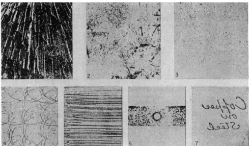
4.3. Special Applications 202 4.3.1. Structure of Steel 202 4.3.2. Structure of Nonferrous Metals 207
4.3.3. Surfaces 207 Inclusions 208 Frictional Transfer 208
Porosity and Discontinuities of Protective Coatings 209
Tin on Iron 211 Tin on Copper Base Alloys 211
Chromium Plating 211 155
1 5 6 Η. \ V . H E R M A N CE A N D Η . V . W A D L O W
Page
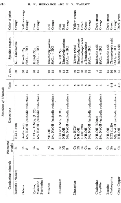
Lead Coating 212 Organic Finishes 212 4.3.4. Minerals 214 4.3.5. Quantitative Applications 218
Estimation of the Dissolved Alloy 220
Measurement of J · t 220 Measurement of D 221 Area of Print 223 Comparison Techniques 223
4.3.6. Electrography of Salt and Structural Patterns 226
References 227 1. IN T R O D U C T I ON
1.1. Surface Analysis
Ordinarily, chemical analysis is employed t o obtain information concerning the mass composition of a specimen. A sample is so selected a s t o be completely representative, even though t h e specimen be hetero
geneous in character. This composite sample is then rendered uniform b y appropriate treatment, for example, b y solution, a n d t h e analytical operations are carried out on t h e resulting product.
Such an approach purposely avoids differentiation of the nonuni- formities in t h e structure of the specimen. N u m e r o u s occasions arise, however, when knowledge is required of b o t h t h e composition a n d t h e distribution of materials present on a surface. Surfaces often receive special t r e a t m e n t t h a t changes their character from t h a t of t h e body as a whole. T h u s protective coatings, organic or inorganic, m a y be applied.
Mechanical processing such as rolling, grinding, polishing or a n y frictional operation against another substance m a y change surface structure a n d introduce foreign substances. T h e deterioration of surfaces b y a t m o s pheric agents (dusts and gases) produces films, t h e examination of which m a y lead to corrective measures.
I t is a fundamental requirement in the examination of such surfaces t h a t a very thin film must suffice for sample. Moreover, simple identifica
tion is not always enough. Often a diagnosis is possible only when t h e exact distribution and form of the surface components can be charted.
T h e composition of a metal plating m a y be known b u t its continuity m a y be in question. T h e shape, size, and orientation of inclusions in rolled stock m a y be as i m p o r t a n t as their composition.
Another kind of surface purposely created t o give information con
cerning the structure of a body is m a d e b y cutting through t h e mass in a specified direction and polishing a n d examining t h e resultant surface.
This examination particularly requires methods of distinguishing t h e
ELECTROGRAPHY A N D ELECTRO-SPOT TESTING 157 structural units as t h e y appear in the exposed surface. Upon this differentiation are based t h e techniques of metallography.
Thus, t h e second requirement of surface analytical m e t h o d s is t h e localization of t h e identified products t o permit recognition of significant distributive p a t t e r n s . Recognition of this need was u n d o u b t e d l y a factor in t h e early development of microchemistry, especially in its relation t o petrography a n d mineralogy.
T h e classical approach t o differential surface analysis involves explora- tion of t h e surface under t h e microscope a n d t h e isolation of questioned areas b y micromanipulative means. Samples so obtained are then analyzed b y microanalytical, spectrochemical or other sensitive tech- niques. I n certain cases, t h e identifying reactions m a y be carried out directly on t h e surface u n d e r examination as in t h e etching of metallo- graphic specimens a n d t h e staining of minerals. Generally speaking, this technique has r a t h e r limited applicability. Color reactions suffer reduction of sensitivity against t h e poor background usually afforded.
I t is generally difficult t o confine t h e colored products over t h e area of reaction so as t o define t h a t area. On t h e other hand, it is very often possible t o transfer an extremely thin layer from a surface t o an inert absorptive material without serious loss of distributive patterns, if t h e chemically prepared m e d i u m is pressed into intimate contact with t h e specimen. P a p e r is t h e most common example of such a material. I t is moistened with a suitable dissolving agent which a t t a c k s t h e surface.
T h e soluble products transfer b y diffusion t o t h e cell-like interstices of t h e fibrous m a t . These, aided b y t h e adsorptive character of cellulose, limit lateral diffusion, preserving t h e local p a t t e r n s . Color reactions, used in conjunction with such a transfer are provided with a very favor- able background a n d once t h e reaction products are precipitated (fixed), various t r e a t m e n t s can be applied t o increase b o t h selectivity a n d sensitivity.
1.2. Chemical Contact Printing
T h e first application of such a m e t h o d was m a d e by B a u m a n n t o determine t h e location of sulfides in steel alloys. I t was termed " T h e Chemical Contact P r i n t M e t h o d (3). T h e polished metal specimen containing sulfide segregations is pressed against a sheet of photographic paper previously soaked in dilute sulfuric acid. T h e liberated sulfide ion then reacts with t h e silver halides in t h e paper t o produce a black stain over t h e area of the original inclusion. T h u s a print of t h e shape a n d distribution of t h e sulfide inclusion is obtained. An extension of this m e t h o d was m a d e b y Neissner (42) t o detect phosphorous segrega- tions in iron alloys a n d copper a n d nickel in their alloys. Gutzeit,
158 Η. W. HERMANCE A N D Η. V. WADLOW
Gysin, a n d Galopin (27) employed both hardened filter paper a n d gelatin coated paper more generally t o obtain prints of other alloys a n d of polished mineral specimens.
I n most uses of contact printing t h e surface m u s t be brought i n t o solution chemically. Control of this process is the most difficult p a r t of t h e method. Sometimes buffered solutions having moderate acidity or alkalinity, or complex-forming salts which exert selective dissolving action m a y be used. T h u s sulfide tarnish films on silver or copper are not readily attacked, even by relatively strong acids. Potassium cyanide however, forms stable silver a n d copper complexes, liberating t h e sulfide ion for reaction with lead carbonate treated paper. Excess cyanide does not interfere. I n a great m a n y cases, however, solution of t h e surface is obtainable only by the use of drastic agents such as strong acids or alkalies. This is particularly true of metal surfaces. Such agents prevent the immediate fixation b y precipitation of t h e transferred material, hence favor lateral diffusion a n d loss of print detail. T h e y are not readily removable after completion of t h e transfer and m a y interfere with the application of subsequent color reactions. T h e course of t h e solution is difficult to control so as t o obtain uniform removal of a definite thin layer. Quantitative comparisons are rarely possible.
However, when a favorable combination of reagents can be found, t h e contact printing m e t h o d is extremely useful. T h e m e t h o d does h a v e serious limitations, among which are: a, restrictions in t h e choice a n d use of dissolving agents; b, difficulty of controlling the process of solution;
c, since the transfer depends entirely on t h e diffusion of t h e dissolved material into the printing medium, printing is necessarily slow, a n d some lateral diffusion cannot be avoided.
1.3. Electrolytic Transfer
Where the surface to be printed is conducting a n d ionizable, a m e t h o d of transfer can be used which is far superior to the simple contact method.
This method is based on t h e electrolytic solution of t h e surface a n d acceleration of t h e dissolved ions t o provide controlled transfer into t h e printing medium. Such a transfer process is rapid, under instant q u a n t i tative control, utilizes neutral, noninterfering electrolytes for dissolving the surface a n d t h e electrical field acts t o prevent lateral diffusion of ionic material.
I n 1929, H . Fritz (8) a n d A. Glazunov (19), working independently, both published m e t h o d s employing electrolytic solution of a metal speci
m e n t o drive its ions into a paper reaction medium. E a c h of these workers h a d rather specialized and, a t t h e same time, quite different objectives. Fritz used a very carefully controlled anodic solution of t h e
ELECTROGRAPHY A N D ELECTRO-SPOT TESTING 159 metal t o transfer known quantities t o paper. T h e resulting s t a n d a r d s were used t o s t u d y t h e sensitivity of various identification reactions such as those used by Feigl in his spot-test methods. For this reason, Fritz termed his technique t h e " E l e k t r o - T u p f e l - M e t h o d e . " His arrangement consisted of a clock-driven metal d r u m cathode, around which was wrapped t h e paper, moistened with t h e color-producing reagent, a n d when necessary, a suitable electrolyte. T h e anode, furnishing ions of the metal u n d e r study, was in t h e form of stylus resting lightly on t h e rotating d r u m . W h e n a potential is applied, solution of t h e anode a n d t h e reac- tion of its ions produces a uniform streak on the moving paper. T h e density of this streak, expressed, for example* in micrograms per centi- meter of length, could be controlled quite precisely by controlling t h e applied current. This was done b y use of a v a c u u m tube, coarse adjust- m e n t being obtained b y stepwise control of grid potential, fine adjust- m e n t b y control of the filament heating current. A milliammeter in the circuit a n d the known speed of d r u m travel permitted calculation of dissolved metal b y applying t h e F a r a d a y law.
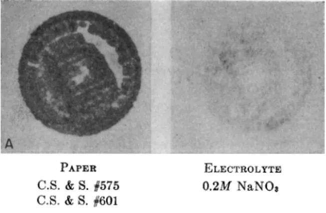
Glazunov first applied anodic solution t o t h e reproduction of macro- structure details in metal specimens, particularly ferrous metals. This he did b y pressing t h e polished specimen surface against paper moistened with an electrolyte capable of producing colored reaction products with t h e metal ions. T h e paper rested on a cathode plate of aluminum or stainless steel. A typical electrolyte was potassium ferrocyanide. W h e n a relatively small potential was applied for a few seconds, a differentiation of macrostructure was obtained in t h e resulting print whenever t h e structural p a r t s a n d crystal orientations were not equally anodic a n d therefore dissolved at different rates. Because this technique h a d as its p r i m a r y objective the reproduction of surface features in t h e form of a print, Glazunov called it t h e " E l e c t r o g r a p h i c " method.
1.4. Historical Review
I n later papers, Fritz (9-16) continued to develop t h e idea of the
" E l e c t r o - T u p f e l " technique, preferring this t e r m t o t h e " E l e c t r o g r a p h i c "
designation of Glazunov. Fritz broadened t h e coverage of " E l e c t r o - T u p f e l " methods t o include all tests based on electrolytic solution or precipitation of ions. I n this he departed considerably from t h e original concept of transfer a n d fixation of surface material a n d much of his work falls outside t h e scope of this chapter.
Fritz recognized t w o m e t h o d s of obtaining electrolytic solution.
One was t o apply an outside source of potential t o t h e plate a n d specimen.
T h e other was t o utilize internal electrolysis b y directly connecting t h e plate a n d t h e specimen with t h e electrolyte-soaked paper between them,
160 Η. W . H E R M A N CE A N D Η . V . W A D L O W
forming a galvanic cell in which solution of the anode specimen or a portion of it would depend on the electromotive relation between the two metals. Selective solution in a multiphase alloy t h u s is obtainable, according t o Fritz. Two general transfer methods were also described.
I n one, a print is obtained b y pressing t h e specimen against t h e paper spread on a plate. I n the other, either t h e specimen or t h e paper is moved so t h a t a streak is obtained, t h u s avoiding polarization b y a continual supply of fresh electrolyte a n d providing a means of controlling the time factor by the speed of m o v e m e n t between paper a n d specimen.
I n later papers, Glazunov (20, 21, 22) proposed the qualitative analysis of alloys by the electrographic method. H e extended the m e t h o d to include the detection of iron, silver, nickel, cobalt, copper, bismuth, zinc, lead, cadium, tin, antimony. Jirkovsky (36, 37, 38) used t h e electrographic m e t h o d for detecting nickel and cobalt in steel a n d for the identification of conducting minerals, as did also Galopin (17) Hiller (30, 31, 32) and Yushko (48, 49).
E . Arnold (2) combined the spot test methods of Feigl a n d t h e electrographic m e t h o d of Glazunov by transferring the sample elec- trolytically into paper, then testing for the metal ions by dropwise addi
tion of reagents. Yagoda (46, 47) has m a d e new use of the electrographic method in an interesting application for the localization of inorganic ions in plant a n d animal tissue. This application is different in t h a t t h e material is not brought into solution, b u t rather, its migration into t h e printing medium is promoted b y electrolysis.
T h e quantitative applications of electrography h a v e received some attention b u t considerable exploratory work is still indicated before its full possibilities are known. Glazunov a n d Krivohlavy (25) published a detailed report of work done on the estimation of nickel in nickel steel.
M . Garino a n d R. C a t t o (18) h a v e estimated small quantities of b i s m u t h in copper from the intensity of the cinchonine iodide print. Glazunov a n d Drescher (23) have determined t h e q u a n t i t y of lead in lead-tin alloys, where t h e lead is present in concentrations above 0 . 2 5 % .
2. EQ U I P M E N T, MA T E R I A L S, A N D MA N I P U L A T I VE TE C H N I Q U ES
2.1. Basic Technique of Electro-Transfer
Basically, the electrographic arrangement is quite simple. I t consists of two metal surfaces between which is sandwiched a layer of absor
bent paper or other porous material, moistened with electrolyte. Pres
sure is applied t o the surface t o insure intimate contact. W h e n con
nected t o a potential source, t h e metal surfaces form t h e anode a n d
ELECTROGRAPHY A N D ELECTRO-SPOT TESTING 1 6 1
cathode of an electrolytic cell. When, as is most common, t h e specimen is t h e anode, its ions move into t h e paper w h e r s t h e y react with either t h e ions of t h e electrolyte or with an added reagent t o produce a n iden- tifiable colored product. Occasionally anions in thin conducting films such as sulfide or chloride need t o be identified. T h e n t h e specimen is m a d e t h e cathode. I n either case, t h e electrode opposite t h e specimen is a n inert metal or one chosen t o avoid interfering reactions. I n very special applications, t h e outside source of potential m a y be eliminated a n d t h e metals joined b y a low resistance conductor. Assuming suffi- cient electromotive dissimilarity between t h e metals, a galvanic cell is then formed in which t h e internally generated potential is t h e driving force for t h e electrolytic transfer of t h e specimen material. As Fritz points out, t h e chief a d v a n t a g e of this m e t h o d lies in t h e automatic control of t h e cell voltage when critical electrolytic separations are desired.
If t h e anode a n d cathode surfaces are b o t h flat a n d parallel a n d pressed evenly against t h e paper, a uniform electrical field is obtained with t h e shortest p a t h normal t o t h e metal surfaces. Ions move into t h e paper, therefore, with practically no lateral diffusion. If t h e y are precipitated ("fixed") immediately, t h e distribution p a t t e r n formed b y t h e ions leaving t h e metal surface can be preserved with great fidelity, even though several successive chemical t r e a t m e n t s m a y be needed t o obtain the final identification product. This control of lateral diffusion by t h e electrical field makes t h e electrographic print of Glazunov m u c h superior in its rendition of detail t o t h e chemical contact print.
Elaboration of t h e a p p a r a t u s m a y v a r y in practice, depending on whether t h e objective be simple spot testing, surface printing, or a more q u a n t i t a t i v e result. Factors over which control m a y be necessary are current, voltage, time, a n d pressure. Manipulative considerations such as shape, size, a n d accessibility of t h e test specimen m a y also influence t h e form of t h e equipment t o be used. There appears t o be no single unit capable of serving all purposes equally well. F o r this reason, several types of equipment will be described a n d their applicability discussed.
2.2. Cell Arrangements and Accessories
T h e simplest a p p a r a t u s for electro-transfer operations consists of a flat metal plate, suitably m o u n t e d a n d provided with connection to t h e current source. This is shown schematically in Fig. l a . Such a base plate of aluminum or stainless steel m a y form one electrode or it m a y be used simply as a convenient contacting surface on which t o rest flat specimens to be explored by t h e electro-spot testing technique. These
162 Η. W. HERMANCE AND Η. V. WADLOW
inexpensive metals rarely interfere when used as cathodes if t h e impreg
nated paper is not left too long in contact without potential. A plan which makes for flexibility is to provide an assortment of auxiliary plates of different metals. These m a y be placed interchangeably on t h e base plate, t h u s providing a n y t y p e of electrode surface needed, including the specific metals required for t h e galvanic couple in internal electrolysis as well as small plates faced with gold or platinum, or plates of graphite when inert electrodes are essential.
In special cases, the possibility of interfering reactions makes it undesirable to have the opposite electrode surface directly in contact with the area of paper which receives the specimen ions. This m a y be avoided by the use of an outer ring electrode placed around the specimen on the paper which is held on a glass plate (Fig. l b ) . T h e electrical
FIG. 1
field in this case is no longer through the thickness of the paper, b u t rather in t h e plane of the paper, radiating from the point of specimen contact. T h e relatively long p a t h t a k e n by the outwardly moving ions raises the effective resistance of the paper, increasing printing time. I t also creates possibilities for electrocapillary separations which have been little explored.
The simple base plate is ordinarily used when small, easily manip
ulated specimens are t o be spot tested or roughly printed and critical pressure control is not necessary. A 3 by 4-inch plate is convenient.
On a reagent paper of this size, a n u m b e r of small objects can be tested on the same sheet a n d compared. Division of the sheet into numbered squares facilitates recording the results. A surface of this size also provides ample area for streak tests m a d e by drawing some particular point on t h e specimen over the paper.
Electrical connection to t h e specimen is established by flexible cords terminating in a variety of clips and probes. Where the specimen has a flat area and can be rested on the paper, a test probe can be used t o m a k e contact and to transmit pressure. Where the irregular shape of t h e
ELECTROGRAPHY A N D ELECTRO-SPOT TESTING 163
FIG. 2
specimen makes it necessary to hold it in the h a n d and orient it on t h e paper, an " a l l i g a t o r " clip m a y be used. Fine instrument parts, wire, pins, etc., too small for convenient manipulation in the h a n d m a y be held in jewelers' pin vises. These should have flexible leads connecting t o t h e jaws through the handle.
Large, immovable specimens such as castings, tanks, structural members, etc., require a somewhat different procedure. T h e plate is
164 Η. W. HERMANCE A N D Η. V. WADLOW
replaced by a small " s p o t t i n g " electrode, held against t h e paper-covered test area. A t y p e used b y t h e authors consists of an aluminum b u t t o n with rounded edges, a b o u t 1 cm. in diameter. I t is provided with a flexible ball joint a t t h e connection t o t h e handle so as t o be self aligning.
An elaboration of such an electrode has a spring clamp for holding t h e impregnated paper on t h e electrode surface a n d carries a b a t t e r y of
( I N S U R E S SMOOTH MOVEMENT OF INNER CYLINDER)
FIG. 3
flashlight cells in the handle. Spotting t h u s is m a d e a simple manipula
tive operation a n d t h e testing of difficultly accessible areas is facilitated.
Figure 2 shows t h e base plate, control circuit, a n d b a t t e r y supply assem
bled as a convenient, portable unit, together with spotting electrodes a n d other accessories.
W h e n emphasis is placed on the reproduction of surface p a t t e r n s , placement of t h e specimen a n d regulation of pressure t o provide i n t i m a t e contact become important. Some form of clamping arrangement is
ELECTROGRAPHY AND ELECTRO-SPOT TESTING 165 needed to hold the cell elements together a t a fixed unit pressure. Several devices are described in published m e t h o d s (18, 28, 41, 47) b u t the impor- tance of maintaining a constant a n d reproducible pressure seems not t o have received the attention it deserves. Glazunov devotes very little discussion to the actual a p p a r a t u s used to obtain electrographs.
Where a p p a r a t u s has been described, it usually consists of a base on which is m o u n t e d an insulated electrode platen. An a r m or yoke, supported over this platen, carries a spring, screw, or a weighted rod which applies pressure to the specimen.
FIG. 4
T o be of universal use, however, the electrographic printing device should provide a wide range of pressure adjustments so as t o furnish the desired unit pressure on areas varying from t h a t of a screw head t o several square inches. Placement a n d removal of the specimen should involve a minimum of manipulation t o avoid blurring of t h e image.
An a p p a r a t u s which fills most electrographic needs where extreme pressures are not necessary is shown in Fig. 3. I t consists of a screw press in the base of which is m o u n t e d a depressible table, supported on a coil spring. This table holds t h e electrographic setup, which is suitably insulated from the screw frame a t the base. I t is removable a n d inter- changeable springs provide several ranges of pressure. For most pur- poses, a spread of from 10 to 300 pounds suffices. An adjustable sleeve on one post of the screw carries a scale which measures t h e depression of the table as pressure is applied. T h e indicating member a t t a c h e d t o
166 Η. W. HERMANCE AND Η. V. WADLOW
FIG. 5
the table is notched around the sleeve and thus it serves the additional purpose of preventing the table from turning. T h e sleeve is first adjusted to bring the zero point to the indicator level for t h e particular loading of the table. Pressure applied by the screw is then measurable from the scale reading by applying calibration d a t a for the spring used. Connec-
ELECTROGRAPHY AND ELECTRO-SPOT TESTING 167 tion t o t h e t o p electrographic member is m a d e through t h e screw frame so t h a t t h e circuit is closed only when t h e pressure is applied.
Figure 4 shows a commercial electrographic press (Fisher Scientific Co., Pittsburgh, Pa.) in which t h e pressure is adjusted by m e a n s of a compression spring a n d t h e values indicated on an engraved scale. T h e accompanying control unit has a b a t t e r y selector switch, a current- polarity switch a n d a rheostat for current adjustment. This press has been used b y t h e authors and found very satisfactory for general purposes.
Work done b y the authors has indicated several advantages in the use of high pressure in electrography where extreme detail is desired, as in t h e s t u d y of t h e m i n u t e porosity of plated surfaces a n d organic finishes.
A Carver laboratory hydraulic press, capable of pressures u p to 20,000 pounds was employed for the purpose a n d it performed very satisfactorily.
T h e press platens were covered with bakelite plates, i-inch thick, for insulation a n d t h e electrographic sandwich was placed between them.
T o facilitate operation of the press, the top member was provided with a heavy screw a n d h a n d wheel. T h e hydraulic p u m p was used only to build u p t h e desired pressure. T h e modified pressure is shown in Fig. 5.
2.8. Current Supply and Control
Choice of current supply for electrographic tests will be governed by t h e frequency of use a n d b y t h e size of t h e areas tested, since t h e latter will determine t h e volume of current needed. Also the choice will depend on whether t h e tests are t o be m a d e in t h e laboratory or with portable field equipment. For relatively small test areas, p r i m a r y cells are entirely satisfactory, the N o . 6 size dry cell being suitable for labora- tory uses, while pocket flashlight cells can be used for portable units, where t h e object is spot testing rather t h a n electrographs of large areas.
Where a considerable a m o u n t of routine laboratory testing is done, storage batteries are more reliable. Current from A.C. mains can be stepped down with a suitable transformer a n d converted to D.C. with a copper oxide rectifier, providing a power source requiring no attention. An especially attractive feature of this source of power is the very excellent voltage regulation afforded b y t h e use of variable transformers such as the Variac. There appears t o be no objection to a slight pulsation in any practical uses of electrography and an elaborate filter is not needed to smooth out t h e D . C . output. F o r a discussion of t h e use of rectified A.C. in electroanalysis, t h e reader is referred t o a note b y A. J. Lindsey (40).
Circuit details will v a r y with t h e degree of regulation needed. For qualitative spot testing, the circuit m a y be very simple, consisting of t h e battery, a push-button switch, a n d possibly an inexpensive milliammeter.
168 Η. W. HERMANCE A N D Η. V. WADLOW
In comparing a series of tests reproducibility becomes more i m p o r t a n t . Some control of time, current, and voltage then m a y be necessary.
Successful electrographic printing often depends on reproducing experi
mentally determined conditions. T h e need for precise control in quanti
tative work is obvious.
A general laboratory circuit, capable of a d a p t a t i o n to all types of electro-transfer is shown in Fig. 6. For use with batteries, t h e circuit contains t h e following equipment:
1. A b a t t e r y selector switch which cuts in one cell a t a time, t h u s affording stepwise control of the applied voltage.
MILLIAMMETER (1 - 5 , 1 - 5 0 , 1 - 5 0 0 )
χ
ι
ELECTRO
GRAPHIC CELL
( β ) BATTERY CIRCUIT
SWITCH (INTERNAL ELECTROLYSIS)
STEP-DOWN VARIABLE , TRANSFORMER , TRANSFORMER (4:1 RATIO, 100 WATT)
COPPER-OXIDE RECTIFIER (2 STAGE, 1-1.5 AMP
DELIVERY)
CHOKE COILS (0.2 HENRY J AT 15 AMPS, 2 - 3 OHMS DC)]
( b ) RECTIFIER CIRCUIT
FIG. 6
2. Two rheostats in series, one about 25 ohms, t h e other, about 250 ohms. These should be capable of carrying about 50 w a t t s without overheating. T h e 25 ohm rheostat is used for a low external resistance circuit, which is best for maintaining a nearly constant voltage at t h e printing cell. For constant current conditions, a high external resistance is needed a n d is obtained with the 250 ohm rheostat
3. A polarity switch for changing t h e direction of t h e current through the printing cell.
4. A milliammeter, preferably one with two or three scale ranges, covering 1 t o 500 milliamp., with a selector switch for these ranges.
5. A voltmeter, 0 to 10 volts range, 1000 ohms/volt. B o t h of these meters should be of t h e zero-center type. An optional addition t o t h e circuit is a timing switch. Accurate timing becomes i m p o r t a n t when it is desired to calculate the q u a n t i t y of ion dissolved, or at least to dis
solve the same q u a n t i t y in successive tests. A switch of the t y p e used
ELECTROGRAPHY AND ELECTRO-SPOT TESTING 169 in photographic timing, capable of a n y setting from 1 to 60 seconds is very satisfactory. I t will be noted in the circuit diagram t h a t provision has been m a d e for closing t h e circuit between the electrodes through the milliammeter, without t h e external power. This permits t h e use of internal electrolysis with t h e milliammeter in t h e circuit t o indicate t h e progress of t h e reaction.
F o r use with rectified A . C , the circuit is t h e same as for b a t t e r y operation except t h a t t h e variable transformer, rectifier a n d filter replace the b a t t e r y and selector switch.
2.4. Transfer Media
T h e porous or permeable medium used in the transfer process acts as a reservoir for t h e electrolyte, determines the spacing between the electrode surfaces and controls the electrolytic p a t h s . I t receives t h e ions from the specimen surface and limits their diffusion a n d the diffusion of their reaction products so t h a t distributive p a t t e r n s are preserved and a satisfactory print is obtained. Often a succession of t r e a t m e n t s with reagents and washes m u s t be m a d e before the print is rendered specific.
Rendition of detail is successful in such cases only if the transferred m a t e - rial remains fixed sufficiently well to withstand these t r e a t m e n t s .
T h e choice of the transfer medium will be determined b y t h e purposes of t h e test and b y t h e subsequent processing operations. I n electro-spot testing, t h e primary objective is rapid a n d specific identification tests with a reasonably accurate localization of identifiable products. T h e printing of fine detail does not fall within its scope. Identification of a single component in an alloy or other mixture m a y require the removal of interferences b y immersion of the spot print in various dissolving a n d masking reagents with washing a n d drying as intermediate steps. Such operations are facilitated when t h e printing medium has a relatively open capillary structure b u t a t t h e same time possesses sufficient wet strength to permit handling without t h e risk of disintegration. An open structure also introduces little electrical resistance above t h a t of t h e electrolyte, t h u s reducing the printing time. This is desirable in spot testing.
T h e material which appears best t o meet the general requirements of electro-spot testing is a hardened filter paper such as Schleicher and Schull #576 or W h a t m a n #50. These papers are of sufficiently fine texture t o permit reproduction of distributive p a t t e r n s down t o a fraction of a millimeter and are a t t h e same time sufficiently open in structure to insure fairly rapid printing a n d processing. T h e y are hardened enough t o have t h e desired wet strength, b u t not to the point where the fibers have become fused a n d t h e porosity lost as in t h e case of t h e so-called
" p a r c h m e n t " paper.
170 Η. W. HERMANCE AND Η. V. WADLOW
I t is generally advantageous to employ a thick, soft paper beneath the printing paper. This provides a cushion, improving the contact, particularly if the specimen surface is slightly rough. T h e printing paper then is in contact only with the specimen and a n y interference caused by contact with the opposite electrode is minimized. This thicker backing paper also increases the capacity for electrolyte, lessening the likelihood of drying out when long printing times are required or when several specimens are to be printed successively on the same paper. A thick, soft filter paper such as t h a t used in spot testing (Schleicher and Schiill #601) or photographic blotting paper are satisfactory materials.
For electrographic prints, in which delicate p a t t e r n s are to be recorded, absorbent paper is less satisfactory. The fine detail is largely lost against the relatively coarse fibrous structure of unsized paper. A material must be used which has a structure- finer t h a n the finest detail to be recorded. In this respect, there is a similarity in the requirements of the electrographic, a n d the photographic image. This at once suggests the use of gelatin or gelatin coatings as a medium for electrography.
T h e idea of employing such a base for chemical contact prints is not new.
M. Neissner (42) used gelatin coated paper, impregnated with various reagents to print inclusions and segregations in metal specimens.
T o obtain suitably coated papers, earlier workers dissolved t h e silver halides out of photographic papers. However, a gelatin coated paper is now supplied b y t h e E a s t m a n K o d a k Co. as " I m b i b i t i o n P a p e r . " T h e paper base is heavily filled and is supplied in two weights. T h e "single w e i g h t " material is better for electrographic purposes, since it offers less resistance to t h e passage of ions.
Since gelatin is microscopically structureless, coated papers place no lower limit on t h e detail recordable. Such limits will still exist, b u t t h e controlling factors will be the sensitivity of the color reaction a n d t h e diffusibility of t h e ions or reaction products in t h e gelatin. H u n t e r , Churchill, a n d M e a r s (33) have pointed out t h a t t h e diffusion of ions in t h e gelatin medium is very slow. Because of this slow diffusion, t h e transfer of ions from the specimen to t h e gelatin surface is more rapid t h a n movement through the gelatin toward t h e opposite electrode a n d a concentration occurs about the point of entry. This concentration of transferred material at t h e gelatin surface results in sharper a n d more delicate electrographic prints for two reasons. First, t h e threshold concentration for a given color reaction is reached quickly a n d with relatively little solution of t h e specimen surface. Consequently, a trace of material can be recorded which might escape detection on filter paper where rapid diffusion would prevent a t t a i n m e n t of t h e reaction threshold. Second, slow diffusion limits t h e spread of transferred
ELECTROGRAPHY AND ELECTRO-SPOT TESTING 171 material around t h e point of entry, rendering t h e image of t h a t point more perfect. I t is even possible t o employ soluble reaction products in gelatin a n d t o obtain good detail. T h e electrolyte m a y be chosen so t h a t no colored, insoluble or nondissociating products are formed with t h e ions under test. A " l a t e n t " print results which contains t h e t r a n s - ferred ions in reactive form. This print can be explored a n d spotted with various reagents, including those which, because of their instability, could not be employed in direct printing.
T h e combination of dense filling a n d gelatin coating raises t h e resist- ance of t h e imbibition paper considerably above t h a t of filter paper for a given electrolyte. Allowance m u s t be m a d e for this in determining t h e printing conditions. T h e diffusion of fluids is naturally m u c h slower in this medium, a n d processing operations therefore require more time.
Before using imbibition paper for printing, it should be soaked for at least 10 minutes t o allow complete penetration of t h e electrolyte.
Although t h e gelatin coated paper u n d o u b t e d l y produces t h e best quality prints, commercial sized a n d filled papers are often capable of rendering considerable detail a n d are very m u c h cheaper. T h u s a heavy grade of hectograph copying paper has been used with considerable success. Such papers are not pure chemically a n d often contain enough iron t o give a distinct blue background color when ferrocyanide is used as t h e reagent, consequently it would be unwise t o use t h e m on a com- pletely u n k n o w n specimen. For m a n y purposes, however, t h e impurities are not bothersome. This is especially t r u e of routine tests, where cost is a factor a n d t h e effects of t h e paper, once they are known, can usually be discounted.
Occasionally it is desired t o prepare prints on a t r a n s p a r e n t base to facilitate projection a n d microscopic study. Several interesting a t t e m p t s have been made, b u t there is still need for a t r a n s p a r e n t permeable medium which is easy t o prepare and handle. Unplasticized cellophane has been proposed, b u t it has very little capacity for electrolyte a n d shrinks badly on drying. Yagoda (47) minimizes this tendency b y preshrinking prior to impregnation with t h e electrolyte. H e points out t h a t this material is especially a d a p t e d t o t h e printing of iron p a t t e r n s with ferrocyanide, since t h e blue product does not bleed when washed as it does in most other media. Yagoda (46) has also recommended the use of plates of plaster of Paris a b o u t 1-mm. thick formed from a water slurry in a special mold. These plates are sufficiently translucent t o permit examination of t h e image in t r a n s m i t t e d light a n d t h e structure is fine enough t o allow microscopic examination of t h e print detail. This medium possesses some special properties w o r t h y of mention. T h e low solubility of calcium sulfate provides a constant and controlled source of
172 Η. W. HERMANCE A N D Η. V. WADLOW
sulfate a n d calcium ions a n d moistening is all t h a t is necessary. T h e controlled sulfate ion makes this m e d i u m suitable for lead fixation.
Difficultly soluble reagents such as zinc sulfide m a y be incorporated readily b y adding t h e m t o t h e slurry at t h e time of casting. T h e chief drawbacks are t h e fragility of t h e m e d i u m a n d t h e time a n d special technique required for its preparation.
Frequently, electrographic prints of curved or irregular surfaces are required. W h e n t h e irregularities are slight, tin or aluminum foil m a y be used as the opposite electrode a n d cushioned with rubber or felt.
When t h e surface curves sharply, b u t is of such shape t h a t t h e paper can be formed t o it successfully, t h e other electrode can be cast of a low melting alloy such as Wood's metal. T h e specimen surface is first covered with tightly drawn paper a n d the alloy is cast around it. An aluminum foil liner can then be used to avoid interferences.
The greatest difficulty is encountered when t h e specimen surface is such t h a t the printing paper cannot be m a d e t o conform t o it without bursting. One answer t o this problem is suggested b y Yagoda's use of plaster of Paris (46). A plaster cast is m a d e b y filling t h e space between the irregular specimen surface a n d t h e nonconforming plane or curved opposite electrode. T h e cast is dried, impregnated with t h e electrolyte- reagent solution a n d refitted t o t h e surfaces. Electrographic printing then proceeds in t h e normal manner, t h e print being obtained on t h e plaster cast instead of paper.
2.5. Preparation of the Specimen
The t r e a t m e n t of t h e specimen surface will depend on t h e information desired of t h e electro-transfer. If a print is t o be m a d e of inclusions, films, a n d other impurities which m a y be hardly more t h a n surface deep, little should be done t o t h e specimen beyond washing with an inert solvent t o remove loose dusts a n d a n y oily films. On t h e other hand, when a surface is used t o sample t h e composition a n d structure of t h e specimen, every precaution should be t a k e n t o insure t h a t it is repre
sentative a n d free from contamination. For electro-spot testing, a fresh surface obtained b y abrasion ordinarily suffices. Abrasive cloth or paper m a y be used, or better, a water suspension of emery or car
borundum. Small specimens m a y be ground on a glass plate, t o which a few drops of wet abrasive h a v e been added. T h e wet abrasive m a y be applied t o large specimens on cotton or felt. Before printing, t h e specimen should be washed or wiped free of abrasion products.
W h e n structural features are t o be electrographed, preparation, of t h e specimen follows closely t h e procedures used in petrography a n d metal
lography. T h e surface is ground and polished t o a smoothness deter-
E L E C T R O G R A P H Y A N D E L E C T R O - S P O T T E S T I N G 173 mined by t h e fineness of t h e structure under study. Irregularly shaped specimens m a y be m o u n t e d in plastic materials before final polishing, with provision m a d e for electrical connection t o t h e back of t h e specimen.
T h e following a d a p t a t i o n of a m e t h o d proposed b y Y a g o d a (47) provides electrical continuity a n d avoids t h e use of a special moulding press. A collar is first prepared of nonconducting material of a d e p t h a n d diameter sufficient t o enclose t h e specimen. Yagoda uses plastic bottle caps with t h e t o p s ground off. Bakelite, vulcanized fiber, a n d other t y p e s of tubing are obtainable commercially in diameters from 1 t o 6 inches, however, a n d can be used for larger specimens. T h e collar is placed on a metal plate which is covered with a sheet of glazed paper. T h e specimen with t h e test surface rough-ground, is placed inside t h e collar with t h e ground surface resting on t h e glazed paper. This assembly is placed in a n oven at 110°C. for 5-10 minutes, removed, a n d a sealing wax containing an inert filler (silica flour, diatomaceous earth, etc.) is poured in t o fill t h e space between t h e specimen a n d t h e collar, b u t not completely covering t h e specimen. W h e n cool, t h e space above t h e wax is filled with a low melting alloy such as W o o d ' s metal t o provide electrical contact for t h e specimen. W e t polishing of t h e m o u n t e d specimen is t h e n completed.
Usually t h e polishing of specimens for electrographic printing need not be carried as far as in conventional metallography. So long as t h e surface is smooth enough t o contain t h e structural elements in a fairly plane section a n d intimate contact secured with t h e printing medium, good prints m a y be m a d e .
T h e electrode surface used opposite t h e specimen should be cleaned frequently, otherwise tarnish a n d electrolysis products m a y accumulate a n d cause contamination of t h e print as well as false distributive p a t t e r n s due t o uneven current distribution. Aluminum a n d stainless steel b o t h t e n d t o acquire invisible passivating films. A few strokes with fine emery or carborundum paper followed b y wiping with a d a m p cloth after each printing will prevent trouble.
2.6. Standard Specimen Block
T h e effective use of t h e electrographic m e t h o d as a tool in general analysis a n d research requires a continuing development of m e t h o d s t o meet particular problems. T h e behavior of metal combinations with given electrolytes, reagents, conditions of printing a n d aftertreatment m u s t be determined b y testing specimens of known composition. W h e n these are handled one at a time, t h e task becomes unnecessarily laborious and t h e a d v a n t a g e s of immediate comparison are lost. A b e t t e r plan is t o print all t h e specimens simultaneously on t h e same paper. Condi-
174 Η. W. HERMANCE AND Η. V. WADLOW
FIG. 7
thick, t o provide electrical contact in t h e press. Phosphor bronze coil springs support t h e pellets in t h e holes and m a k e contact between t h e m and t h e copper plate. These springs are so adjusted t h a t when t h e pellets are depressed flush with t h e block face, a pressure of a b o u t 200 g. is exerted on each. T h u s a n y desired combination or configuration of these interchangeable specimens can be arranged in t h e block which is t h e n placed in t h e electrographic press, m a d e anodic, and t h e print obtained in t h e usual manner.
T h e specimens are cleaned b y grinding individually on a glass plate with fine emery or carborundum suspension. A special holder is used t o keep t h e grinding plane normal t o t h e pellet axis. T h e metal contact plate is removable from t h e b o t t o m of t h e block b y loosening four screws.
tions then are identical and the results can be compared readily at any point in the processing.
Simultaneous printing of a n u m b e r of specimens m a y be accomplished with the mounting block shown in Fig. 7. T h e s t a n d a r d specimen con
sists of a cylindrical pellet, 18-mm. long a n d 12 m m . in diameter. These cylinders slide freely in holes drilled through a block of bakelite, hard rubber, lucite, or other impervious insulating material. T h e block is 30-mm. high and t h e b o t t o m is faced with a plate of copper about 3-mm.
ELECTROGRAPHY AND ELECTRO-SPOT TESTING 175 This facilitates cleaning of t h e block, plate, a n d springs. A square block of 10 cm. side will easily accommodate t w e n t y holes, which is sufficient for most purposes.
Assume t h e problem t o be t h e identification of one component of a n alloy containing a n u m b e r of metals. Pellets of t h e alloy a n d of all t h e metals likely t o be present are placed in t h e block. P r i n t s are m a d e with t h e electrolyte, electrolysis conditions, a n d color producing reagents best suited t o t h e metal t o be identified. Interferences b y other metals are noted a n d masking t r e a t m e n t s tried until a development sequence is found which eliminates all spots on t h e print except those of t h e pure specimen of t h e metal under test a n d t h e alloy containing it. For exam- ple, a test is desired to distinguish leaded brass from plain brass. T h e block contains copper, zinc, tin, lead, iron, plain and leaded brass speci- mens. Developed with sodium sulfide, t h e print gives colors with copper, lead, iron a n d b o t h brasses. However, t r e a t m e n t with potassium cyanide, t h e n with acetic acid and water clears all spots b u t those of lead and leaded brass.
T h e specimen block technique also m a y be used quantitatively. A series of s t a n d a r d brass pellets containing known concentrations of lead are placed in t h e block, printed, and developed. T h e unknown, printed under identical conditions, is compared with t h e known series and t h e lead content estimated from t h e densities of t h e prints.
2.7. The Technique of the Electro-transfer
T h e physical operations of t h e transfer are quite simple a n d should be fairly evident from t h e descriptions of t h e a p p a r a t u s in t h e earlier p a r t of this chapter. I n assembling t h e sandwich, t h e larger, more t a b u l a r member is normally placed at t h e b o t t o m . Usually this will be t h e base plate or press platen, b u t occasionally t h e specimen m a y be of such shape a n d dimensions as to reverse t h e order. T h e pad, con- sisting of t h e printing material a n d t h e soft backing paper, is immersed in t h e appropriate electrolyte, drained, blotted, a n d placed on t h e elec- t r o d e with t h e printing surface t o w a r d t h e specimen. T h e sandwich is completed b y t h e bringing of t h e other electrode member down on t h e paper. T h e latter m a y be held with t h e h a n d for simple spot testing and rough printing or t h e sandwich m a y be clamped in t h e electrographic press for longer a n d more precise operations. T h e paper should not be too wet, a n d before t h e circuit is closed care should be t a k e n t o blot u p a n y excess electrolyte squeezed from t h e sandwich when pressure is applied.
For flawless electrographic reproduction, films or bubbles of air at t h e specimen surface m u s t be avoided. Bubbles in t h e matrix of t h e
17G Η. W. HERMANCE A N D Η. V. WADLOW
printing medium block t h e movement of ions and m a y produce con
centration changes which would affect t h e final p a t t e r n . Somewhat greater care is therefore indicated in t h e impregnation of t h e medium a n d in t h e m a n n e r of bringing t h e surfaces together. Unsized paper should be slowly lowered edgewise into t h e electrolyte so t h a t air is driven out b y the capillary climb of t h e fluid. After immersion for a minute or longer, it should be agitated in t h e b a t h t o remove a n y accu
mulated bubbles before withdrawing. Gelatin or sized papers require soaking for 10 minutes or longer t o permit full penetration of t h e elec
trolyte. A trace of Aerosol or similar wetting agent often m a y be added without interference t o improve wetting, both of the paper and the metal surfaces.
W h e n manipulative details can be so arranged, it is advantageous t o apply t h e printing medium to the specimen surface first, using a rubber roller t o work out a n y bubbles unavoidably trapped. E v e n irregular specimens which have t o be m o u n t e d face downward can be so handled if t h e printing paper is cut t o t h e exact contour of t h e specimen surface. T h e backing paper is laid over t h e base plate or platen and is kept fairly moist. T h e specimen, with t h e printing paper rolled on, is then inverted on t h e backing paper, a n d pressure is applied. T h e excess electrolyte squeezed out is thoroughly removed b y blotting.
I n making electrographic prints, t h e pressure t o be applied will v a r y with t h e condition of t h e specimen and t h e n a t u r e of t h e printing medium a n d is best determined for t h e individual case. I t should be sufficient t o insure intimate contact at all points. Thus, if pinholes in a plated surface are t o be reproduced, t h e printing medium, or at least t h e elec
trolyte, m u s t be forced into contact with t h e base metal a t t h e b o t t o m of such discontinuities. Pressures of 1000 lb./sq. in. or more h a v e been found desirable in such cases a n d t h e use of t h e hydraulic press for obtain
ing t h e m has already been indicated. For most purposes, pressures of 25-100 lb./sq. in. will be found satisfactory.
T h e current and time required for printing will be determined b y t h e area of t h e specimen and b y t h e q u a n t i t y of t h e ion which m u s t be transferred t o produce a satisfactory print density. Assuming t h a t a low enough voltage is used so t h a t practically all of t h e energy is applied to t h e solution of t h e specimen, F a r a d a y ' s second law establishes t h e relation q u a n t i t a t i v e l y :
T . 96,500 * Κ - A ,t.
I "t = — Q » (1)
where / is the current in amperes, t, the time in seconds,
A, the area of the specimen surface in cm.8
Q, the equivalent weight of the dissolved metal in g.
ELECTROGRAPHY A N D ELECTRO-SPOT TESTING 1 7 7 Κ is a specific factor based on the sensitivity and color producing power of the
reaction used. It is expressed in g./sq. c m .2 of the ion needed to produce a print of the desired density.
T h e units in t h e above equation are large for electrographic purposes a n d it is convenient t o express area a n d current together as current density. T h e following equation is therefore suggested:
. , 96.5 - k ,0.
id-t = — ^ — , (2)
where id is the current density in Ma./sq. cm.
t, the time in seconds,
k, the specific factor, expressed in micrograms per sq. cm.
Q is the equivalent weight as in the first equation.
T h e factor k is not precise, its value depending on t h e print density best suited t o t h e purposes of t h e test. A greater print density is needed, for example, in t h e detection of pinholes t h a n in t h e reproduction of larger details. I n general, it m a y be said t h a t a satisfactory color inten
sity is obtained with most reactions when t h e q u a n t i t y of t h e ion elec- trolyzed is between 20 a n d 70 μg./cm2. Yagoda suggests a n average figure of 50.
Example: A copper print, using zinc sulfide paper, requires 20 micrograms/cm.2
for good recognition of detail. The current density used is 15 milliamp./cm.2 The time required is obtained from the equation:
15t — ^ ' 1 ^ from which t is 4.1 seconds, ol.o
T h e value of t h e current t h r o u g h t h e electrographic cell determines the potential across it a n d this in t u r n , influences t h e phenomena occurring at t h e electrodes. T h e voltage measured across t h e electrographic cell is t h e algebraic s u m of t h e I R drop t h r o u g h t h e p a d a n d t h e internal e.m.f. generated b y t h e t w o electrodes when t h e y function as a p r i m a r y cell. T h e internal e.m.f. is determined b y t h e potential difference between t h e t w o electrodes in t h e electrolyte used. I t m a y oppose t h e applied current or it m a y aid it, depending on whether t h e material serving as t h e cathode of t h e electrographic sandwich is anodic or cathodic relative t o t h e specimen. T h u s , if a n aluminum cathode were used a n d the specimen being dissolved anodically were a copper alloy, t h e e.m.f.
of t h e sandwich would oppose t h e applied potential. N o printing would then occur until t h e applied voltage is m a d e t o exceed t h a t of t h e cell.
On t h e other hand, if conditions were reversed, a n d a n a l u m i n u m alloy were being dissolved against a cathode of copper, theoretically no outside potential would be needed. I t s application would simply speed u p t h e process, reducing t h e time a n d providing a better rendition of detail.
178 H. W. HERMANCE AND Η. V. WALDOW
I n t h e printing of metallic specimens, t h e current density, in general, should be so controlled t h a t t h e anodic voltage does not greatly exceed t h e solution potential of t h e metal to be detected. T h e n practically all of the electrical energy is used for t h e solution of t h e metal a n d F a r a d a y ' s law holds. Very high current densities m a y raise t h e voltage t o t h e decomposition potential of the electrolyte, when gassing will occur, driving the electrolyte out of the sandwich a n d producing poor prints.
When t h e specimen is not homogeneous b u t is m a d e u p of materials having different potentials, anodic and cathodic areas will exist on its surface. Then, in addition to the potential required t o balance t h e back- e.m.f. of the cell as a whole, a further potential will be t h a t which is necessary t o render all areas of the specimen surface anodic. An excellent discussion of t h e conditions on such a surface has been provided b y Hunter, Churchill, and Mears (33), A slightly condensed version is here given:
"Let us assume that a specimen A contains an inclusion of a more cathodic mate
rial C. The open circuit potentials of the two are denoted by the points A and C respectively in Fig. 8. These two materials, being in physical contact are short- circuited and a liquid circuit is furnished by the electrolyte-filled paper of the cell.
The anodic material will polarize along the curve A-B, while the cathodic material will polarize along the curve C-B, until the point Β is reached. At this point the potential of the entire specimen will be that corresponding to the point Β (neglecting the small IR drops which exist in the electrolyte) and a self-generated current will be flowing in such direction that only the anodic material will be dissolved. Thus, with
out an applied current, the more cathodic inclusion would not be dissolved and hence would not be detected.
"However, as current is applied to the specimen, it will polarize along the curve B-D-E. Until point D, which corresponds to the open-circuit potential of C, is reached, only the anodic material A will be dissolved. Beyond point D, both A and C will dissolve. Thus practically all elements may be forced from the surface of the specimen into the printing medium regardless of their open-circuit solution potentials.'' These voltage requirements t h u s set a minimum value for the current density. T h e latter m u s t be such t h a t t h e potential across t h e cell is sufficient t o render t h e specimen completely anodic. Suppose, for example, a copper inclusion in a zinc surface is t o be printed. T h e difference of potential between these two metals in t h e electromotive series a m o u n t s t o 1.23 volts. T h e potential in t h e electrographic cell will be somewhat different because of t h e difference in t h e electrolyte, b u t it will be of t h e same order. I n a sandwich using filter paper soaked in 2 % sodium nitrate, t h e initial resistance measures about 90 o h m s / c m .2 T h e current density necessary t o print t h e copper, therefore, should be 1.23/90, or 14 milliamp./cm.2; which corresponds t o point Β in Fig. 8.
Experimentally, it was found t h a t a copper print in a zinc specimen
ELECTROGRAPHY A N D ELECTRO-SPOT TESTING 179 could not be obtained until applied voltage reached 1.6 when a n aluminum cathode was used. T h e current density under these conditions measured 17 m i l l i a m p . / c m .2 a t t h e start of t h e printing, corresponding t o point D in Fig. 8.
W h e n a printing p a d of higher resistance is used, t h e necessary potential c a n b e obtained with a lower current. T h u s , in t h e example just given, if gelatin paper is used, t h e resistance measures a b o u t 200 ohms p e r c m .2 A copper print is obtained with a current density of only 8 milliamp./cm.2, instead of 17.
C U R R E NT D E N S I T Y
FIG. 8
T h e foregoing discussion h a s dealt in some detail with heterogeneous surfaces in which t h e components display their individual solution tendencies. W h e n t h e specimen is a single phase alloy, however, a different behavior is observed. F r o m such solid solutions, t h e com- ponent metals go into electrolytic solution in t h e same proportion as their concentration in t h e alloy. Glazunov discusses this behavior as it is illustrated in iron-nickel alloys a n d h a s m a d e use of it in a quanti- tative application of electrography. This subject will receive further a t t e n t i o n later in t h e chapter.
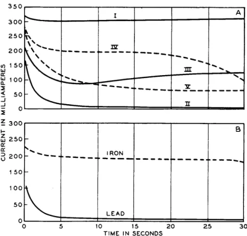
T h e resistance of t h e electrographic cell will increase a s t h e transfer progresses a n d polarization effects increase. Ions concentrate a t t h e electrodes a n d a r e depleted in t h e intermediate layers. Precipitation of reaction products removes further ions a n d tends t o seal off a n d isolate t h e anode surface. T h e resistance increase in t h e electrographic cell
180 Η. W . H E R M A N CE A N D Η . V . W A D L O W
will be accompanied b y a simultaneous decrease in t h e current. If t h e resistance in t h e external circuit were negligible, t h e product I R t h e n would remain constant and t h e cell voltage would not change. I n practice, some external resistance will always exist. T h e decrease in current therefore will not exactly compensate t h e increase in t h e cell resistance since t h e current will fall in proportion t o t h e increase in t h e total resistance of t h e circuit. Hence, t h e voltage will slowly rise a n d t h e greater t h e external resistance relative t o t h e sandwich resistance, t h e more pronounced will be t h e voltage increase. F r o m this, it should be clear t h a t if it is desired t o hold t h e voltage constant, or nearly so, its adjustment should be m a d e at t h e b a t t e r y selector switch r a t h e r t h a n b y adding resistance. T h e control resistance should be used only t o obtain regulation between t h e steps of t h e b a t t e r y selector, a n d should be as low as possible. Under these conditions, t h e slight rise in voltage during printing can be compensated b y manipulation of t h e resistance.
Regulation t o within 0.1 volt is usually easy this w a y when t h e ion dis
solved does not exceed 100 m i c r o g r a m s / c m .2
If, on t h e other hand, t h e current is t o be held constant t o facilitate calculation of t h e dissolved ion, this is best accomplished b y employing a high external resistance relative t o t h e resistance of t h e cell a n d a sufficiently high circuit voltage t o obtain t h e desired drop at t h e printing cell. Since t h e current is relatively constant in this arrangement, t h e cell voltage will rise almost as its resistance rises. I t is therefore desirable for q u a n t i t a t i v e work, t o employ transfer conditions which involve t h e least possible polarization effects. For this purpose, sensitive reactions requiring only small quantities of transferred material are t h e most suitable.
3. EL E C T R O L Y T E S, RE A G E N T S, A N D DE V E L O P I NG PR O C E S S ES
8J. Production of the Image
T h e simplest production of t h e electrographic image is exemplified b y t h e printing of iron inclusions and alloyed copper in duralumin.
Prints are obtained directly with paper moistened with 2 % potassium ferrocyanide in which t h e iron particles are reproduced as blue ferric ferrocyanide against a reddish background of cupric ferrocyanide. T h e ferrocyanide serves b o t h as electrolyte a n d color-producing reagent.
I t gives strongly contrasting colors with copper a n d iron and none with aluminum a n d t h u s is ideally suited t o t h e particular problem.
On t h e other hand, if we wish t o test a bronze specimen electro- graphically for alloyed manganese, we are not favored with so con
venient a reagent. T h e manganese print is not obtainable directly,
ELECTROGRAPHY A N D ELECTRO-SPOT TESTING 181 b u t r a t h e r as t h e product of a series of transforming operations. First, a " l a t e n t " print is produced electrographically, in which t h e transferred metals are obtained as basic sulfates. This print is next t r e a t e d with ammonia a n d hydrogen peroxide a n d thoroughly washed. This step removes t h e copper a n d converts t h e manganese t o t h e h y d r a t e d dioxide.
Finally, t r e a t m e n t of t h e print with benzidine acetate develops t h e m a n - ganese image as t h e fugitive blue oxidation product of benzidine.
These examples illustrate t h e two general approaches used in t h e development of t h e electrographic image. Direct printing results when the color producing reagent is present a t t h e time of t h e transfer. T h e alternative m e t h o d is t o employ t h e transfer as a separate operation with appropriate precautions t o prevent diffusion of t h e products. This is followed b y one or more developmental operations, t h e final product being a selective colored print. Naturally, where t h e conditions of t h e problem permit, direct printing is t o be desired. Such a procedure is limited, however, t o cases where (a) t h e electrolyte contains a reacting ion or group which is stable a n d capable of giving a colored product with t h e metal t o be detected under t h e conditions of t h e electrolysis a n d (b) where t h e specimen surface yields no interfering ions. A funda- mental limitation t o t h e direct printing procedure derives from t h e fact t h a t few of t h e so-called specific reagents possess t h e property of reacting with a single metal out of a group of possible metals without t h e introduc- tion of special t r e a t m e n t s a n d " m a s k i n g " reagents t o overcome inter- ferences. Specificity in t h e spot testing techniques of Feigl is obtained largely b y combining t h e use of group selective color-producing reagents with p r e p a r a t o r y t r e a t m e n t s designed t o suppress or t o remove inter- fering substances. Another limitation t o direct printing is illustrated in t h e case of t h e manganese bronze where no suitable color reaction existed for t h e m a n g a n o u s ions. W h e n given a separate t r e a t m e n t , however, t o oxidize t h e manganese a n d remove t h e interfering copper, t h e print is capable of development with benzidine and t h e test is fairly specific for manganese.
Some organic reagents, for example, diphenylcarbazide or benzidine, undergo oxidation a t t h e anode with t h e formation of interfering colored products, hence could not be used in t h e direct printing process although they are entirely satisfactory for use in outside development.
Aside from overcoming t h e limitations of direct printing, t h e use of t h e " l a t e n t " or undeveloped print has certain advantages. F o r exam- ple, if one is dealing with an u n k n o w n specimen, identification of its components requires t h e stepwise application of group a n d specific reagents. A single undeveloped transfer can be given m a n y tests with such reagents, b y spotting or brush-streaking. I t can be conditioned b y