Dual Channel Micro fl uidics for Mimicking the Blood − Brain Barrier
Boris Buchroithner, Sandra Mayr, Fabian Hauser, Eleni Priglinger, Herbert Stangl,
Ana Raquel Santa-Maria, Maria A. Deli, Andras Der, Thomas A. Klar, Markus Axmann, Dmitry Sivun, Mario Mairhofer, and Jaroslaw Jacak*
Cite This:ACS Nano2021, 15, 2984−2993 Read Online
ACCESS
Metrics & More Article Recommendations*
sı Supporting InformationABSTRACT:
High-resolution imaging is essential for analysis of the steps and way stations of cargo transport in
in vitromodels of the endothelium. In this study, we demonstrate a micro
fluidic system consisting of two channels horizontally separated by a cell-growth-promoting membrane. Its design allows for high-resolution (down to single-molecule level) imaging using a high numerical aperture objective with a short working distance. To reduce optical aberrations and enable
single-molecule-sensitive imaging, an observation window was constructed in the membrane
vialaser cutting with subsequent structuring using 3D multiphoton lithography for improved cell growth. The upper channel was loaded with endothelial cells under
flow conditions, which showed polarization and junction formation. A coculture of human vascular endothelial cells with pericytes was developed that mimics the blood
−brain barrier. Finally, this dual channel micro
fluidics system enabled 3D localization microscopy of the cytoskeleton and 3D single-molecule-sensitive tracing of lipoprotein particles.
KEYWORDS:
micro
fluidics, 3D multiphoton lithography, single-molecule imaging, blood-brain barrier, endothelial cells, 3D particle tracking
T he development of reliable in vitro models for human blood barriers, which allow for monitoring of drug delivery processes or processes occurring in tissue disorders, is highly desirable. Additionally, faithful mimicking of these interfaces provides us the opportunity to study transport without the use of human/animal in vivo models, which are limited by ethical concerns. Accessibility to in vitro models facilitates tuning of microenvironmental conditions and understanding the biological, biochemical, and biophysical effects of chemo-physical treatment.
1−3 The majority of these in vitro models are based on a micro
fluidic platform, which introduces
flow dynamics into the biological system. Cells either form a growing layer on top of a 2D surface or are used as a barrier between two micro
fluidic channels.
4−10 These cellular constructs facilitate the formation of vascularization networks directly on the micro
fluidic chip which can be generated either via endothelial-lined patterned channels or via self-assembled networks.
11Fluorescence imaging is frequently used as the primary measurement technique for standard micro
fluidic systems that are used to observe cellular dynamics or the transport of biomolecules across barriers.
12,13 Micro-
fluidic systems have been used to characterize cell reactions
after treatment with exosomes, using time-lapse confocal microscopy or to quantify mitochondrial dynamics, morphol-
ogy, and nanoscale mitochondrial protein distributions using live cell and super-resolution microscopy.
12Multiphoton lithography (MPL) has recently been used to structure arbitrary nano/microscopic features into micro
fluidic systems.
14MPL is suitable for 3D structuring with lateral and axial resolutions of
∼200 and 500 nm, respectively.
15The high
flexibility in feature sizes, material properties, and 3D writing capability makes MPL a well-suited method for structuring mechanical barriers, which can also be used for cell support.
However, a micro
fluidic chip for mimicking di
fferent kinds of blood barriers with the feature of providing for single- molecule-sensitive imaging in 3D is still lacking. Most of the current blood
−brain barrier (BBB) models are based on the transwell system,
16,17where live optical imaging is not possible at all or likely only with low NA (i.e., high working distance) objectives. Under such conditions, neither single-molecule- sensitive nor 3D imaging is possible at the desired resolution.
Received: November 5, 2020 Accepted: January 19, 2021 Published: January 22, 2021 Downloaded via 193.224.44.72 on February 3, 2022 at 09:16:07 (UTC). See https://pubs.acs.org/sharingguidelines for options on how to legitimately share published articles.
In the existing microfluidics,
18,193D tracking is challenging due to the thickness of the channels and the membrane
’s porosity.
Moreover, thick membranes reduce the contact between cells and introduce optical aberrations, consequently reducing achievable imaging resolution. The platform proposed in this paper allows for 3D imaging and tracking of single molecules that move within or along cells forming the blood barrier. Our micro
fluidic system consists of two channels, which are horizontally separated by a membrane, enabling cocultivation.
To enable transport across the membrane, we have introduced a window produced via laser cutting that was subsequently
filled with a 3D polymer into which a complex, de
fined geometry of holes and support structures was engineered. The combination of subtractive and additive manufacturing allows creation of complex structures and enhancement of the functionality of the
final device.
20−22We were able to show
that when endothelial cells (ECs) were introduced into the system they became polarized on the membrane and developed interendothelial junctions. By coculture of ECs with pericytes, a model of the BBB
23was demonstrated. In summary, our microfluidic chip enables 3D single-molecule- sensitive imaging using a high numerical aperture (NA) objective with a short working distance. In a showcase experiment using CD34
+-ECs in the micro
fluidics device we were able to perform 3D localization microscopy of the cytoskeleton and 3D single molecule tracing of high-density lipoprotein (HDL) particles.
RESULTS AND DISCUSSION
The primary goal of this study was to develop a micro
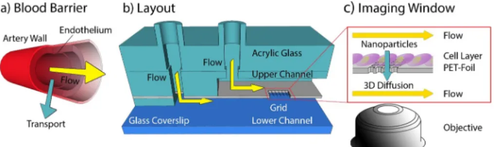
fluidic system that mimics cellular blood vessel barriers (Figure 1a) providing a means to study the transport of biomolecules (e.g.,
Figure 1. General design of the microfluidic system. (a) Schematic drawing of a vessel with a yellow arrow indicating the direction offlow and a turquoise arrow indicating the transport across the endothelium. (b) Design of the microfluidic channel consisting of a glass coverslip as substrate and two parallel channels on top of each other separated by a polyethylene foil with a hole carrying an MPL-structured grid. An acrylic glass piece provides additional mechanical stability. (c) Sketch of the foil seeded with cells. The yellow arrows indicateflow along the channel and the turquoise arrow indicates diffusion of biomolecules and nanoparticles across the cell layer. This process is monitored using a high NA objective.Figure 2. Modification of the PET foil. (a) Schematic illustration of the MPL setup. A fs-pulsed laser beam was focused through an objective (NA 1.25) in dip-in configuration. Movement of the focal spot within the photoresist was performedviaa combination of a galvanometric mirror and a 3-axis stage. Wide-field imaging was used for simultaneous monitoring of the laser processing. The instrument can also be operated in a confocal imaging mode for precise identification of an interface with an APD. (b, c) Schematic illustrations of 3D scaffold fabrication. First, a hole was cut into an impermeable PET foil using laser ablation (1030 nm indicated by red color beam (b)). A bright-field image is shown below. In (c), the hole was covered with the photosensitive resin (yellow drop), and the opening in the foil was closed with a 3D structure using MPL (515 nm indicated by green colored beam). The bright-field image below shows the same position after the hole was filled with a polymer structure. (d) Scanning electron microscopy (SEM) image of the 3D grating inside the foil. (e) SEM image of a grating on the top and bottom side of the foil; the top grid has a mesh size of 6μm, and the bottom side has a larger (12μm) mesh size. In addition, the 3D structure axial connectors (30μm) are observable.
lipoprotein particles, extracellular vesicles, but also lipids and hormones) across the barrier.
24The layout of this dual channel micro
fluidics system allows for cocultivation of various cell- types and imaging of their cellular processes (e.g., extracellular vesicles uptake, cell
−cell interactions) via single-molecule- sensitive
fluorescence microscopy. In order to introduce a cell barrier between the micro
fluidic channels, a MPL structure was introduced which enables an application-speci
fic optimization of the barrier (i.e., observation window) (see
Figure 1b,c and Figure S1).Structure of the Microfluidic Device.
Our aim was to design a micro
fluidic channel with two
flow channel compart- ments, separated by a membrane suited for cell cultivation.
The channel was designed to provide for nanoscopic imaging of single molecule transport to living cells. In order to use objective lenses with a NA > 1.4 and a working distance of 300
μm, the height of the micro
fluidics compartment above the imaging window (i.e., cell membrane interface) was adjusted to
∼
250
μm. A cross-section of the micro
fluidic chamber is depicted in
Figure 1b. The microfluidic chamber consists of a coverslip substrate, a spacer that forms the bottom channel, a 30
μm thick polyethylene terephthalate (PET)-foil that separates the lower and upper channels, and spacers which de
fine the upper channel including inlets. The top was covered with hard acrylic glass which provided mechanical stability and rigidity for the whole micro
fluidic device. A detailed description of the layout can be found in
Figure S1a. ThePET-foil has proven to be well suited as a cell substrate.
5,25,26However, although transparency is provided, distortion of the
fluorescence signal was observed; moreover, such impermeable PET-foil does not allow the study of di
ffusion of single
molecules and ions that move across the foil. To permit di
ffusion and reduce distortions in optical measurements, custom-de
fined, and shaped holes were cut into the PET-foil by femtosecond (fs)-long laser pulses. Here, without loss of generality, a star-shaped geometry has been chosen (Figure 2b,
Figure S1bdepicts alternative forms). Typically, three to six starlike holes with a characteristic length of 170
μm (tip-to-tip distance) were cut in one micro
fluidic device.
Thereafter, a 3D grating was created that acts as a barrier between the two compartments. The 3D grating inside the star-shaped holes was structured using multiphoton lithog- raphy, allowing for high
flexibility in the geometry and polymer composition of the structure. Furthermore, writing of a grating- shaped cell support reduces the contact area of the cells with the substrate (i.e., minimizes the arti
ficial contact area) and simultaneously increases the direct interaction area between cells. For 3D printing, we used a biocompatible BisSR- photoresist,
27which allows for structuring with sub-200 nm feature sizes. The photoresist was placed on top of the hole, and MPL in dip-in con
figuration was performed (Figure 2c).
In the dip-in configuration, the photoresist is used as the immersion medium. The
final structure consisted of a 100
μm
×
100
μm grid with a customizable periodicity. The criticalsteps for production of the imaging window are shown in
Figure 2b,c: a laser cut star-shaped hole in the PET-foil and thesame hole
filled with a suspended 3D polymeric grating. The
flexibility of MPL structuring allows facile tuning of grid periodicity and shape at both sides of the hole and enables cell type dependent customization. In the transwell based BBB model, it was shown that increase of the membrane pore size from 0.4 to 3
μm substantially increases the contact between
Figure 3. Cell culture in the microfluidic device. (a) Bright-field image, 3 days after cultivation with ECs in a microfluidic device. (b) Bright- field image of a zoomed grid populated with ECs underflow conditions. Two-colorfluorescence images of cells on top of the scaffold show nuclei (Hoechst 33342, blue) and cell junctions marked with an Alexa647-conjugated anti-CD31/PECAM-1 antibody (red). (c) Confocal images of ECs on top of a grating. Cells were stained with Alexa647-conjugated anti-CD146 (red) antibodies and Alexa488-conjugated anti- CD31 (blue) antibodies. Thez-cross sections show that CD146 (red) is homogeneously distributed on the cell membrane and CD31 is localized on the apical side. (d) Scaffolding consisting of a grid with two different periodicities oriented in a checkered pattern. The overlay image (right) displays ECs (red) cultivated for 3 days underflow conditions in the upper channel, cocultured with bovine pericytes (green).Pericytes stained with Nuclear Green dye (green) were in the lower channel. ECs were labeled with Alexa647-conjugated anti-CD31/
PECAM-1 antibody, and their nuclei were stained with Hoechst 33342.
cells and resulted in greater barrier strength.
16Here, we employ a grating with an upper layer periodicity of 6
μm and a lower layer periodicity of 12
μm,
filling the star-shaped hole (Figure 2d). The layers are interconnected by 30
μm high polymeric structures. The larger mesh size of the bottom grid facilitates penetration of cells. In contrast, the upper mesh is su
fficiently dense to inhibit ECs invasion.
Additionally,
flexibility in terms of functionalization of the polymeric structures is shown in
Figures S1d,e. The figure shows grids with a 12
μm periodicity, made of protein- repellent pentaerythritoltriacrylate/ethylene glycoldiacrylate (PETA
−PEGDA) polymer
28−30and ring substructures made of biotinylated PETA (Figure S1d) or pentaerythritol triacrylate/2-carboxyethyl acrylate (PETA-CEA) monomers (Figure S1e). Both polymers, employed for the ring substructures, can be used to immobilize the desired proteins.
29,30To show protein binding selectivity, we incubated the entire structure with Alexa647-streptavidin. As shown in the
fluorescence image of the polymer structure (Figure S1f), streptavidin e
fficiently bound to the biotinylated PETA containing the ring substructure and did not bind to the protein repellent rectangular grid consisting of PETA
−PEGDA. Such selective polymer functionalization
28,30−32enables local immobilization of biomolecules inside the imaging window and could potentially be used for cell-type- specific stimulation.
29,33,34The optical properties of the polymer were optimized to minimize auto
fluorescence and maximize transparency.
27This enabled
fluorescence microscopy measurements, even at a single molecule level (Table S1). The biocompatibility of the foil and polymers used for the grid structuring facilitates cell seeding and culturing within the channels. We used a syringe pump to introduce a constant
flow of 0.2 mL/h in the upper channel. In the lower channel, medium was replaced every 2 h or if the pH change (i.e., color change of phenol red) was visually observed. We used a two-cell-type system wherein we seeded primary endothelial cells (CD34
+-ECs), or alternatively
human umbilical vein endothelial cells (HUVECs) to form an endothelial cell layer in the top channel. The
flow-speed was adjusted to 70
μm/s, which is in the same order of magnitude as natural
flow-speeds (300
μm/s for capillaries
35).
Optimization of cultivation and imaging. In the next step, cell cultivation inside the micro
fluidic channel was optimized.
Cells were grown for 3
−5 days under a constant, directional nutrient
flow of 0.2 mL/h. This produced cells that were partially aligned with the direction of
flow (arrow in
Figure 3a)and which formed a con
fluent monolayer complete with interendothelial junctions on both the foil and the grid structures. To characterize the cell-layer,
fluorescence micros- copy was used. Cell positions were visualized using a Hoechst 33342 stain for the nuclei (blue). We visualized the cellular network by labeling cell
−cell junctions with an Alexa647-anti- CD31/PECAM-1 antibody (Figure 3b). A two-color
fluo- rescence image in the right panel of
Figure 3b demonstrates adense cell layer, indicated by the cell−cell junctions and the labeled nuclei. Overall, the cell nuclei showed no signs of apoptosis, and cells on the polymer grid formed a dense monolayer, with interdigitated contacts to neighboring cells.
Generally, morphology of the cells on the grid was indistinguishable from cells on the PET substrate, demonstrat- ing once again the excellent biocompatibility of the coated polymer grid, which readily supports the growth of primary endothelial cells for longer time periods.
ECs exposed to
flow typically exhibit a cell polarization
36resulting in a change in the protein distributions between the apical and basal membranes. Here, we used CD146/MCAM and CD31/PECAM-1 proteins as polarization markers.
37It is expected that, upon polarization, CD31 will have a higher apical density
38,39and that CD146 will show a more homogeneous distribution.
40,41For imaging, we stained ECs inside the micro
fluidic channel with Alexa647-conjugated anti- CD146 (red) antibodies and Alexa488-conjugated anti-CD31 (blue) antibodies (Figure 3c). To demonstrate the polarization of ECs, confocal imaging of the endothelial cells on top of the
Figure 4. Super-resolution microscopy within the microfluidic device. (a) Bright-field image of a cell-covered grid. (b) 3D direct stochastic optical reconstruction microscopic (STORM) image of the cell’s cytoskeleton (the same area as in panel a). Here, the cytoskeleton is labeled with Alexa Fluor 647 conjugated phalloidin, which specifically binds actin. The average signal-to-noise-ratio in the super-resolved image was∼13 on suspended cells and∼10 on cells lying directly on the gratings (due to a higher background). (c) Fluorescence image of cells on a structure after incubation with Atto647N conjugated HDL particles. Cells were incubated with HDL particles for 20 min under flow conditions. (d, e) Individual trajectories of HDL particles in 3D (black). The green, blue, and red lines represent the projections inxz,yz, andxyaxes, respectively (number of frames: 641 (d) and 377 (e)).
microfluidic device is well-suited for cocultures of two cell types based on our ability to tune the periodicity and geometry of the 3D grid as well as the hole size for tailoring the cell
−cell interaction area. We used ECs and bovine pericytes cultured on the upper and lower sides of the grid, respectively (Figure
3d), to mimic the BBB;23however, any other desired cell combination can be cocultured. The endothelial cells were cultured for 3 days under
flow conditions in the upper channeland then cocultured with bovine pericytes
42in the lower channel. Direct interactions between the cocultivated ECs and the pericytes form a BBB like structure
23(see
Figure 1a). Forvisualization, the pericytes were stained with Nuclear Green dye (green). To visualize the EC network, the nuclei of
fixed cells were stained with Hoechst 33342 (blue), and the cell junctions were stained with Alexa647-conjugated anti-CD31/
PECAM-1 antibody (red). The right panel in
Figure 3d showsa
fluorescence image of the ECs and bovine pericytes cocultured in the micro
fluidic device. Human vascular ECs were captured on the top of the grid, and the pericytes were imaged on a focal plane below the grid. The images of the separate color channels are depicted in
Figure S3. This resultdemonstrates the applicability of the micro
fluidic device for imaging of cocultivated cells.
Single-Molecule Imaging within the Dual-Channel Microfluidics.
Here, we show that the transport of molecules across the mimicked cellular barrier can be followed with single-molecule sensitivity. In
Figure 4a, we show a bright-field image of a sca
ffold populated with ECs. To prove the micro
fluidic device
’s feasibility for localization microscopy, we stained the cytoskeleton of these CD34
+-ECs with Alexa Fluor 647 conjugated phalloidin. The astigmatism of the signal was used to determine the axial arrangement of the cytoskele- ton.
43,44The refractive index mismatch between the polymer structure and the cells was adjusted using a glucose bu
ffer (n
∼1.42).
Figure 4b shows a super-resolved (3D-dSTORM45) image of the cytoskeleton. Detailed analyses of the super- resolved images revealed that the signal-to-noise-ratio (SNR) in the suspended areas (SNR
∼13) is higher when compared to areas where the cells lie directly on top of the grid (SNR
∼10). This di
fference was minimized due to the low auto
fluorescence of the chosen polymer; nevertheless, the advantage of intentional polymer-free volumes areas in the imaging area is notable.
In a second experiment, we traced
fluorescently labeled HDL particles across human vascular ECs cultivated under
flow conditions. Particles were transported along the cell membrane. The observed movement was consistent with the compartmentation of HDL-like particles between liquor and blood circulation.
46,47We were able to trace the movement of individual HDL particles in 3D and determine their diffusion constants. Projections of the trajectories of two particles are shown in
Figure 4c. Two traces are explicitly depicted inFigure 4d,e, the black line represents the 3D trace, and the green,blue, and red lines represent the projections in xz, yz, and xy
indicate that EVs are taken up by the cells.
CONCLUSION
The platform presented in this paper provides for 3D imaging and tracking of single HDL particles moving across cells grown on an arti
ficial membrane. We show a micro
fluidic system consisting of two channels, which are horizontally separated by a cell growth-promoting membrane. High-resolution imaging is enabled by observation windows introduced into the membrane (we were not able to image single molecules through the PET membrane, the higher background induced by the membranes is clearly visible in
Figure S2). Thesewindows were produced via laser cutting and subsequently
filled with 3D polymer structures. As proof of concept, we seeded our micro
fluidic chambers with ECs and observed cellular polarization and interendothelial junction formation under
flow conditions. A coculture of ECs with pericytesimitating blood
−brain barrier formation was demonstrated. In contrast to other available systems,
16,17our microfluidic model allows coculture, appliance of
flow, live high-resolution microscopy as well as analysis of transport processes at a single molecule level. In a showcase demonstration, 3D localization microscopy of the cytoskeleton and 3D single molecule tracking of HDL particles was performed which showed that HDL particles do not pass through the cell layer.
A di
ffusion analysis of the HDL particles revealed that on average, the particles’ positions varied by x = 3.4
±2.8
μm,y = 2.4
±1.4
μm, and z = 0.26
±0.11
μm, indicating that the HDL particles were not entering cells but rather diffusing along the membrane curvature. In comparison, we were able to show that EVs were taken up by the cells. The average x,y,z- displacements for EVs in ECs were 0.8
±0.4
μm, 0.8
±0.3
μm, and 0.5±0.1
μm, respectively. These data indicate thatEVs move across the membrane and inside the cell. Thus, we conclude that EVs were taken up by the cells in contrast to HDL particles. This result shows the selectivity of the barrier via transferring some molecules while blocking others. Taken together, HDL particles were moving only in two dimensions (on the surface of the cells), indicating that these cells formed a valid blood
−brain barrier model. Note that it is well- described that lipoproteins do not pass the blood−brain barrier; instead, the brain
−liquor has a unique set of HDL like lipoproteins.
51MATERIALS AND METHODS
Fabrication.Lithography System.A scheme of the Workshop of Photonics (WOP, Lithuania) multiphoton lithography instrument is shown inFigure 2a. The instrument is equipped with an ultrashort pulsed laser (CARBIDE, 1 MHz repetition rate, 290 fs pulse duration, Light Conversion, Lithuania) with two available wavelengths. Thefirst harmonic of the laser output (1030 nm) is used for direct laser drilling and the second harmonic output (515 nm) for multiphoton lithography. All stated intensities are peak intensities in the focal plane, calculated from the power measured in front of the objective,
taking the transmission of the objective and a diffraction-limited spot area into account. Writing was performed by a combination of sandwich and dip-in configuration.52 A 3-axis stage (AEROTECH Nanopositioner, USA) was used for sample motion. Optionally, faster lateral writing was performed by a galvanometric mirror scanner (AEROTECH, USA).
Direct Laser Cutting.For laser ablation, thefirst harmonic (1030 nm) of the WOP system laser was used as shown inFigure 2b, left.
The laser beam was focused with a 50×magnification air objective (Mitutoyo, Japan) onto the biocompatible PET foil (biaxially oriented polyethylene terephthalate foil, Bleher). Cutting was performed by moving the focal spot with a velocity of 80μm/s and executed in two steps:first a peak intensity of 1.65 TW/cm2 was used for thefirst cutting, and then the intensity was increased to 1.84 TW/cm2and the was beam shifted closer to the center by 5μm. After a completed run, the foil was lifted by 2.5μm and the cutting procedure was repeated until the inset was cut out. If necessary, the inner discarded part was removed mechanically by means of an ultrasonic bath. To protect the optic from the evaporating material, the PET-foil was sandwiched in- between two glass slides.
Multiphoton Lithography.In order to close the hole with a cell- supporting scaffold, the hole was covered with a droplet of resin (see Figure 2b, right-hand side). Writing was carried out by sandwich writing (two spacers with 170μm and a glass lid with 170μm) using the 50×air objective as described in the previous section and/or in dip-in configuration (Zeiss, 63×, NA 1.25). Due to the lower NA, sandwich writing enables a higher throughput, while dip-in writing has the benefit of small feature sizes and a higher intensity. The photoinitiator of the resin was excited by using the second harmonic (515 nm) of the WOP system. For 2D or 3D structuring, the focus of the laser was traced along a path by 3D stage and/or moving of a galvanometric mirror. To improve attachment between the structure and the foil, a frame (35μm wide and 30μm thick) is written into the hole, usually by the aid of sandwich writing. The hole was closed optionally by a 2D grid or 3D scaffold. The 2D grid consists of quadratic squares with a grid constant of 6μm and a commissioned height of 2μm. Each square was exposed twice, making the resulting bar thickness dependent on the used writing speed of 200μm/s and writing peak intensity of 1.05 TW/cm2. The 3D scaffold was generated by the use of a STL-file. The 3D model consisted of an upper grid (grid constant of 6 μm, bar thickness and height of 1.5 μm) separated to a lower grid by 30μm long spacers with the same bar dimension but a higher grid constant of 12μm. For structuring, a writing speed 1 mm/s and writing peak intensity of 1.58 TW/cm2was used.
Photoresist Formulations. The biocompatible photoresist BisSR was a mixture of 29% of Bis-GMA (Esschem Europe, England) and 71% ethoxylated bisphenol A dimethacrylate (SR348C) (Sartomer, France), and prepared as published.27CEA/PETA was composed of 10 wt.% 2-carboxyethyl acrylate (Sigma-Aldrich, Germany) mixed with PETA. The biotinylated resin consisted of 1 wt.% biotin arylate (Nanocs, Inc., USA) and 99% PETA. The protein repelling resins were made of 20% PEGDA (Sigma-Aldrich, Germany) and 80%
PETA as recently reported.29A photo initiator 1 wt.% of Bis(2,4,6− trimethylbenzoyl)−phenylphosphineoxide (IC 819) was used for all resins. All monomers were stirred with a magnetic stirrer until homogeneously mixed.
Assembly of the Microfluidic Chip. Two microfluidic channels were sandwiched between a microscope coverslip (Menzel 24 mm× 50 mm#1 SPEZIAL, Thermo Scientific) and an acrylic glass piece.
While the microscope coverslip enabled observation of the sample area with high magnification/high NA objectives, the acrylic glass, with openings for tube connectors, made the microfluidic chip rigid and easy to handle. An industrial laser cutting device was used to cut the dimensions and openings of the acrylic glass out of a 3 mm thick sheet. The building blocks with the microfluidic channel structure were cut using a craft cutter (Silhouette Portrait 2).53The individual layers of the channel structure were made from a Bleher 175μm thick PET foil (Optimont 501, Bleher Folientechnik GmbH, Germany) and two kinds of double-sided adhesive tape, Adhesive Research Arcare
90445 (thickness: 80 μm) and 3 M 467MP (thickness: 50 μm) (purchased from adhesives research, Ireland, and local supplier, respectively). The lower channel consisted of a 5 mm wide gap with a circular opening in the middle (radius: 7.5 mm). The upper channel consisted of a rectangular opening of 18 mm by 22 mm. An impermeable 30 μm thick PET foil (Bleher Folientechnik GmbH, Germany) separated the two channels. The same PET foil was used to form a lid on the upper microfluidic channel, which wasfixed to the acrylic glass piece by a double-sided adhesive tape. Likewise, four tube connectors (EV Group, Austria) were fixed to the double-sided adhesive tape. The gap between the acrylic glass cavity and the tube connector was filled with a liquid two-component glue (pico dent twinsil extra hard, Henry Schein, Austria), to prevent leakage from both channels. To assemble the microfluidic chip, each layer was stacked on top of the previous one. As a precaution against leakage, surrounding edges of the microfluidic chip were covered with a thin layer of a UV light curing polymer mixture SR 499 (Sartormer, France) with 2 wt.% IC784 (BASF AG, Switzerland) which solidified during the sterilization process. For sterilization, tube connectors were closed by male Luer stoppers (Carl Roth, Austria) and exposed to UV light for 2 min (Dymax ECE, USA). For the last step, the microfluidic chip was baked at 60°C for 1 h (Memmert GmbH, Germany). If desired, tubing, tube connectors, male Luer stoppers, and acrylic glass pieces can be reused after proper washing with 2-propanol and deionized water.
Cell Cultures.Human Vascular Endothelial Cells.Primary ECs were differentiated from CD34+cells isolated from human cord blood as described23 and were provided in frozen aliquots of 106 cells at passage five by Prof. Fabien Gosselet, Université d’Artois, France.
After thawing, cells were seeded onto gelatin (0.1% in PBS)-coated 10 cm-dishes in ECM-5 medium (ECM from Sciencell) supplemented with 1% endothelial cell growth supplement (ECGS), gentamycin (50 μg/mL, BiochromAG, ref A-2712), and 5% of preselected, heat- inactivated FBS and cultivated at 37 °C, 5% CO2. After reaching confluency, cells were washed once with PBS, detached with a Trypsin/EDTA solution, counted, and reseeded at approximately 2× 10⁵ cells/cm2. Expression of the EC marker CD31/PECAM-1 was confirmed byflow cytometry and immunofluorescence.
Brain Pericytes.Bovine brain pericytes were purchased from Prof.
Gosselet’s group and cultured in DMEM (Dulbecco’s Medium Eagle Modified, Life Technology) supplemented with 2 g/L NaHCO3
(Merck, Austria), 20% heat-inactivated FCS (Sigma-Aldrich, Austria),
L-glutamine, and 50μg/mL gentamycin (Biochrom AG, Germany).
Cocultures of human ECs and pericytes are an established and well- characterized blood−brain model.23,47Co-cultivation protocols were adapted for use in the microfluidics system.
HUVECtert2 Line.Immortalized human umbilical vein endothelial cells (HUVECtert2) were purchased from Evercyte (Vienna, Austria) and cultured in phenol red-free M199 medium (Carl Roth, Karlsruhe, Germany) supplemented with 10% BCS (Sigma-Aldrich, Austria), LVES (Thermo Fisher Scientific, USA), GlutaMAX (100×, Thermo Fisher Scientific, USA), penicillin-streptomycin (100 IU/mL pen- icillin, 100 μg/mL streptomycin), and 20 μg/mL G418 (Gemini, Sussex, United Kingdom) at 37°C and 5% CO2.
Cell Cultivation in the Dual-Channel Microfluidics System.
Human Vascular Endothelial Cells.The UV-sterilized microfluidic system was thoroughly rinsed with PBS, followed by coating of the flow chambers with 0.1% gelatin solution. Next, theflow chambers were rinsed with prewarmed ECM-5 medium, and ECs were seeded into the channel (105cells/cm2). Cells adhered for 1−2 h at 37°C.
Then the tubing was filled with prewarmed ECM-5 medium and connected to the MF system and the syringe pump. Nonadherent cells were removed by rinsing theflow chamber with 1 mL of ECM-5 at aflow rate of 10 mL/h. Next, theflow rate was decreased to 0.2 mL/h, and cells were cultivated for up to 6 days under constantflow conditions. In the lower channel, medium was replaced every 2 h or if the pH change (i.e., color change of phenol red) was visually observed. For immunostaining at the indicated time points, the MF system was rinsed with prewarmed HBSS containing Ca2+and Mg2+,
density of 105cells/cm2. Cells were allowed to settle for 3 h and were then subjected to shear stress via flow of phenol red-free M199 medium applied by a syringe pump connected to the chip providing fresh medium every 3 h (100μL/min, 400μL total volume).
Imaging. Confocal Fluorescence Microscopy. Confocal images were acquired using an inverted laser scanning microscope (Zeiss LSM 700, Medical University of Vienna, Imaging Core Facility) with an oil-immersion objective (Plan-Apochromat, 63×, NA 1.4) or Zeiss LSM 800 (Johannes Kepler University Linz) with an oil-immersion objective (Plan-Apochromat, 40×, NA 1.2). For recording of 3D stacks, the samples were illuminated using 4 solid-state laser lines (405 nm, 488 nm, 555 and 639 nm). The signals were detected using two photomultiplier tubes (PMT). For PMT 1, the followingfilter sets were used: SP 490, SP 555, SP 640 nm and for PMT 2 long-pass filters LP 490, LP 560, LP 640 nm. Images were recorded with the ZEN 2009 black software and evaluations were performed using ImageJ (version 1.52n)54and Gwyddion (version 2.5).55
Actin Staining for dSTORM Imaging. Cells were washed with prewarmed PBS,fixed using 4% paraformaldehyde in PBS for 10 min and washed again. The actin cytoskeleton was visualized using Alexa Fluor 647 conjugated phalloidin (Cell Signaling Technology, Leiden, Netherlands). Actin staining was performed in cytoskeleton buffer with sucrose (CBS) containing 10 mM MES pH 6.1, 138 mM KCl, 3 mM MgCl2, 2 mM EGTA and 0.32 M sucrose according to the protocol from Louise Cramer (MRC Laboratory for Molecular Cell Biology, UCL). Briefly, cells were permeabilized in 0.5% Triton X-100 with CBS, blocked in 10% albumin from chicken egg white (Sigma- Aldrich, Vienna, Austria) and stained for 20 min with 66 nM Alexa Fluor 647 conjugated phalloidin.
Fluorescence Microscopy and 3D dSTORM Image Acquisition.
Images were acquired using a modified Olympus IX81 inverted epifluorescent microscope with an oil-immersion objective (PlanApo N, 60×, NA 1.42, Olympus, Vienna, Austria). Samples were mounted on a XYZ piezo stage (PI Mars; P-562, Physical Instruments) which has nanometer accuracy, combined with a coarse mechanical stage with a travel range of 1 cm×1 cm (Hybrid, JPK Instruments, Berlin, Germany). A tube lens with an additional magnification of 1.6 was used to achieve afinal imaging magnification of 96 (corresponding to a pixel size of 167 nm). ECs were illuminated with a 642 nm laser diode (Omicron-laserage Laserprodukte GmbH, Phoxx 642, Rodgau- Dudenhofen, Germany) and a 488 nm laser (Toptica Photonics, Germany). Signals were collected using an Andor iXonEM+ 897 (back-illuminated) EMCCD camera (16 μm pixel size). The following filter sets were used: dichroic filter (ZT405/488/561/
640rpc, Chroma, Germany), emissionfilter (446/523/600/677 nm BrightLine quad-band band-pass filter, Semrock, Rochester, NY, USA), and additional emission filters: ET 700/75 M, Chroma Technology GmbH, Olching, Germany; ET 525/50 M, Chroma Technology GmbH, Olching, Germany. For 3D measurements, a cylindrical lens (f= 500 mm; Thorlabs, Newton, USA) was placed into the detection path of the microscope.
3D dSTORM Imaging Protocol.Single-molecule photoswitching of the rhodamine dye Alexa Fluor 488 and the cyanine dye Alexa Fluor 647 was performed in a buffer optimized for both dyes (no need for buffer exchange). This buffer contained OxEA as described by Nahidiazaret al.56and was applied to the cells immediately prior to measurements. For imaging, samples were illuminated for 40 ms with a 1.4 kW/cm2excitation intensity (647 nm) and for 20 ms at a 3.3 kW/cm2 excitation intensity (488 nm) on the sample plane (both frame rates: 25 images/s). For image reconstruction, a sequence of
cells’cytoskeletons were more challenging. Closer inspection of the recorded super-resolution image stack showed that the autofluor- escence of the polymer bleaches slowly over the acquisition time and is visible in all frames. Since, stochastic blinkingfluorophores are only visible over a short-range of frames, an averaged image of the stack would result in a constant background image. Thus, a subtraction of this background from each frame in the stack can be used to remove the unwanted autofluorescence. The standard procedure of averaging of all frames and subsequent subtraction of the resulting background from each frame was impossible to apply due to the slowly decreasing autofluorescent signal (resulting from bleaching). Therefore, an advanced software tool for background subtraction was written, where the following procedures were applied. For calculation of the background (averaged) image, each frame was normalized to the prior summation step, which resulted in a more accurate background image.
In the second step, prior to subtraction, the obtained background image was scaled in accordance with the intensity of each frame. The parameters for scaling and offset were calculated by linear regression between the background image and corresponding frame.
High Density Lipoprotein (HDL) Preparation. Plasma was obtained from normolipidemic healthy volunteers. Informed consent was obtained from all subjects. This was approved by the Ethics Committee of the Medical University of Vienna (license no. 1414/
2016). Afterward, HDL particles were isolated by serial ultra- centrifugation60(for a detailed video, see ref61). The apolipoprotein part of the HDL particle was covalently labeled with Alexa647- succinimidyl ester according to the protocol (Thermo Fisher) (for details, see ref62).
Extracellular Vesicle (EV) Preparation. HEK293T cells (ATCC no. CRL-3216) were cultured in Dulbecco’s modified eagles medium (DMEM, Thermo-Fisher, Waltham, MA), high glucose, supple- mented with 10% fetal bovine serum (FBS, Thermo-Fisher), and 1%
penicillin/streptomycin (complete medium) at 37°C in a 5% CO2
atmosphere. Transfection of HEK293T with the GFP-CD63 plasmid (Addgene no. 62964) for overexpression of the GFP-labeled EV marker CD63 was performed with 1μg of plasmid DNA and 2μL of Endofectin Max reagent in 6-well plates. After expansion of the transfected cells for several weeks, GFP+ cells were sorted by fluorescence-activated cell sorting (FACS), single-cell derived clones were isolated and characterized byflow cytometry and microscopy.
For EV isolation, parental or transfected HEK293T cells were cultured to a subconfluent state in DMEM supplemented with 10%
FCS and 1% penicillin/streptomycin. A 20% FCS solution in OptiMEM was centrifuged at 110000g for 12 h to deplete EVs from bovine origin. For collection of the conditioned media, the media was changed to OptiMEM (Gibco, Carlsbad, CA) containing 2% EV-depleted FCS, and supernatants of approximately 130−150× 106cells were collected after 24 h. The cell number and viability of EV producing cells was verified with a CASY cell counter (OMNI Life Science, Bremen, Germany). Cellular debris, apoptotic bodies, and larger EVs were removed from the supernatants by centrifugation at 200g(5 min), 2000g(10 min and 10000g(30 min) at 4°C. Smaller EVs were obtained by ultracentrifugation at 110000g(1 h 10 min) at 4°C (Sorvall MX150, Thermo Fisher Scientific, Waltham, MA) in a fixed angle rotor (Hitachi S58A-0095, Chiyoda, Japan). The pellet was washed in PBS, concentrated by ultracentrifugation, and subsequently resuspended in 30μL of PBS. Samples were stored at
−80°C.
ASSOCIATED CONTENT
*
sı Supporting InformationThe Supporting Information is available free of charge at
https://pubs.acs.org/doi/10.1021/acsnano.0c09263.Movie S1: eGFP-labeled EVs di
ffusing across a 3D structure without cells (AVI)
Movie S2: Static, pseudo-3D reconstruction of diffusing particles in the lower channel (AVI)
Detailed description of the micro
fluidic chip layout;
alternative forms of holes in PET-foil; functionalization of the polymeric structures; auto
fluorescence of the polymer grid for di
fferent excitation wavelength;
cultivation of HUVECs in the micro
fluidic chip; color- separated images of cocultured ECs and bovine pericytes; 3D trajectories of extracellular vesicles di
ffusion in the ECs (PDF)
AUTHOR INFORMATION Corresponding Author
Jaroslaw Jacak−
Department of Medical Engineering, University of Applied Sciences Upper Austria, 4020 Linz, Austria;
orcid.org/0000-0002-4989-1276;Email:
jaroslaw.jacak@fh-linz.at AuthorsBoris Buchroithner−
Department of Medical Engineering, University of Applied Sciences Upper Austria, 4020 Linz, Austria
Sandra Mayr−
Department of Medical Engineering, University of Applied Sciences Upper Austria, 4020 Linz, Austria
Fabian Hauser−Department of Medical Engineering,
University of Applied Sciences Upper Austria, 4020 Linz, Austria
Eleni Priglinger−
Ludwig Boltzmann Institute for Experimental and Clinical Traumatology, AUVA Research Center, 1200 Vienna, Austria
Herbert Stangl−
Institute of Medical Chemistry, Center for Pathobiochemistry and Genetics, Medical University of Vienna, 1090 Vienna, Austria
Ana Raquel Santa-Maria−
Institute of Biophysics, Biological Research Centre, Hungarian Academy of Sciences, H-6726 Szeged, Hungary
Maria A. Deli−
Institute of Biophysics, Biological Research Centre, Hungarian Academy of Sciences, H-6726 Szeged, Hungary
Andras Der−
Institute of Biophysics, Biological Research Centre, Hungarian Academy of Sciences, H-6726 Szeged, Hungary
Thomas A. Klar−
Institute of Applied Physics, Johannes Kepler University Linz, 4040 Linz, Austria;
orcid.org/0000-0002-1339-5844
Markus Axmann−
Department of Medical Engineering, University of Applied Sciences Upper Austria, 4020 Linz, Austria
Dmitry Sivun−
Department of Medical Engineering, University of Applied Sciences Upper Austria, 4020 Linz, Austria;
orcid.org/0000-0002-5531-1354Mario Mairhofer−
Department of Medical Engineering, University of Applied Sciences Upper Austria, 4020 Linz, Austria
Complete contact information is available at:
https://pubs.acs.org/10.1021/acsnano.0c09263
Notes
The authors declare no competing
financial interest.
ACKNOWLEDGMENTS
We thank Heidi Piglmayer-Brezina for taking the SEM images, Andreas Horner for help with confocal measurements, Ilse Kammerhofer for support with the administration organiza- tion, Fabien Gosselet and Julien Saint-Pol for helping with the establishment of the BBB cellular model, and EV-Group GmbH for providing micro
fluidic parts. This work was funded by the Interreg project ATCZ14 and the Austria Science Fund (FWF) project P 31827-B21.
REFERENCES
(1) Hwa, A. J.; Fry, R. C.; Sivaraman, A.; So, P. T.; Samson, L. D.;
Stolz, D. B.; Griffith, L. G. Rat Liver Sinusoidal Endothelial Cells Survive without Exogenous VEGF in 3D Perfused Co-Cultures with Hepatocytes.FASEB J.2007,21(10), 2564−2579.
(2) Twardowski, R. L.; Black, L. D. Cardiac Fibroblasts Support Endothelial Cell Proliferation and Sprout Formation but Not the Development of Multicellular Sprouts in a Fibrin Gel Co-Culture Model.Ann. Biomed. Eng.2014,42(5), 1074−1084.
(3) Rothbauer, M.; Rosser, J. M.; Zirath, H.; Ertl, P. Tomorrow Today: Organ-on-a-Chip Advances towards Clinically Relevant Pharmaceutical and Medicalin VitroModels.Curr. Opin. Biotechnol.
2019,55, 81−86.
(4) Huang, R.; Zheng, W.; Liu, W.; Zhang, W.; Long, Y.; Jiang, X.
Investigation of Tumor Cell Behaviors on a Vascular Microenviron- ment-Mimicking Microfluidic Chip.Sci. Rep.2015,5(1), 17768.
(5) Walter, F. R.; Valkai, S.; Kincses, A.; Petneházi, A.; Czeller, T.;
Veszelka, S.; Ormos, P.; Deli, M. A.; Dér, A. A Versatile Lab-on-a- Chip Tool for Modeling Biological Barriers.Sens. Actuators, B2016, 222, 1209−1219.
(6) Chen, L.-J.; Ito, S.; Kai, H.; Nagamine, K.; Nagai, N.; Nishizawa, M.; Abe, T.; Kaji, H. Microfluidic Co-Cultures of Retinal Pigment Epithelial Cells and Vascular Endothelial Cells to Investigate Choroidal Angiogenesis.Sci. Rep.2017,7(1), 3538.
(7) Sleeboom, J. J. F.; Amirabadi, H. E.; Nair, P.; Sahlgren, C. M.;
Toonder, J. M. J. den Metastasis in Context: Modeling the Tumor Microenvironment with Cancer-on-a-Chip Approaches. Disease Models&Mechanisms2018,DOI: 10.1242/dmm.033100.
(8) Mandt, D.; Gruber, P.; Markovic, M.; Tromayer, M.; Rothbauer, M.; Krayz, S. R. A.; Ali, F.; Hoorick, J.; van Holnthoner, W.;
Mühleder, S.; Dubruel, P.; Vlierberghe, S. V.; Ertl, P.; Liska, R.;
Ovsianikov, A. Fabrication of Placental Barrier Structures within a Microfluidic Device Utilizing Two-Photon Polymerization. Int. J.
Bioprinting2018,DOI: 10.18063/ijb.v4i2.144.
(9) Hudecz, D.; Khire, T.; Chung, H. L.; Adumeau, L.; Glavin, D.;
Luke, E.; Nielsen, M. S.; Dawson, K. A.; McGrath, J. L.; Yan, Y.
Ultrathin Silicon Membranes for in Situ Optical Analysis of Nanoparticle Translocation across a Human Blood-Brain Barrier Model.ACS Nano2020,14(1), 1111−1122.
(10) Kincses, A.; Santa-Maria, A. R.; Walter, F. R.; Dér, L.; Horányi, N.; Lipka, D. V.; Valkai, S.; Deli, M. A.; Dér, A. A Chip Device to Determine Surface Charge Properties of Confluent Cell Monolayers by Measuring Streaming Potential.Lab Chip 2020,20(20), 3792−
3805.
(11) Haase, K.; Kamm, R. D. Advances in on-Chip Vascularization.
Regener. Med.2017,12(3), 285−302.
(12) Tam, J.; Cordier, G. A.; Bálint, Š.; Álvarez, Á. S.; Borbely, J. S.;
Lakadamyali, M. A Microfluidic Platform for Correlative Live-Cell and Super-Resolution Microscopy. PLoS One 2014, 9 (12), No. e115512.
(13) Sharghi-Namini, S.; Tan, E.; Ong, L.-L. S.; Ge, R.; Asada, H. H.
Dll4-Containing Exosomes Induce Capillary Sprout Retraction in a 3D Microenvironment.Sci. Rep.2015,4(1), 4031.
(17) Elbakary, B.; Badhan, R. K. S. A Dynamic Perfusion Based Blood-Brain Barrier Model for Cytotoxicity Testing and Drug Permeation.Sci. Rep.2020,10(1), 3788.
(18) Yeon, J. H.; Na, D.; Choi, K.; Ryu, S.-W.; Choi, C.; Park, J.-K.
Reliable Permeability Assay System in a Microfluidic Device Mimicking Cerebral Vasculatures. Biomed. Microdevices 2012, 14 (6), 1141−1148.
(19) Ahn, S. I.; Sei, Y. J.; Park, H.-J.; Kim, J.; Ryu, Y.; Choi, J. J.;
Sung, H.-J.; MacDonald, T. J.; Levey, A. I.; Kim, Y. Microengineered Human Blood-Brain Barrier Platform for Understanding Nanoparticle Transport Mechanisms.Nat. Commun.2020,11(1), 175.
(20) Tičku̅nas, T.; Perrenoud, M.; Butkus, S.; Gadonas, R.; Rekstyte, S.; Malinauskas, M.; Paipulas, D.; Bellouard, Y.; Sirutkaitis, V.
Combination of Additive and Subtractive Laser 3D Microprocessing in Hybrid Glass/Polymer Microsystems for Chemical Sensing Applications.Opt. Express2017,25(21), 26280−26288.
(21) Jonusauskas, L.; Rekstyte, S.; Buividas, R.; Butkus, S.; Gadonas, R.; Juodkazis, S.; Malinauskas, M. Hybrid Subtractive-Additive- Welding Microfabrication for Lab-on-Chip Applications via Single Amplified Femtosecond Laser Source. Opt. Eng. 2017, 56 (9), 094108.
(22) Sugioka, K. Hybrid Femtosecond Laser Three-Dimensional Micro-and Nanoprocessing: A Review.Int. J. Extrem. Manuf.2019,1 (1), 012003.
(23) Cecchelli, R.; Aday, S.; Sevin, E.; Almeida, C.; Culot, M.;
Dehouck, L.; Coisne, C.; Engelhardt, B.; Dehouck, M.-P.; Ferreira, L.
A Stable and Reproducible Human Blood-Brain Barrier Model Derived from Hematopoietic Stem Cells. PLoS One 2014, 9 (6), No. e99733.
(24) Hudecz, D.; Rocks, L.; Fitzpatrick, L. W.; Herda, L.-M.;
Dawson, K. A. Reproducibility in Biological Models of the Blood- Brain Barrier.Eur. J. Nanomed.2014,6(3), 185−193.
(25) Kuo, Y.-C.; Chung, C.-Y. Transcytosis of CRM197-Grafted Polybutylcyanoacrylate Nanoparticles for Delivering Zidovudine across Human Brain-Microvascular Endothelial Cells.Colloids Surf., B2012,91, 242−249.
(26) Benam, K. H.; Villenave, R.; Lucchesi, C.; Varone, A.; Hubeau, C.; Lee, H.-H.; Alves, S. E.; Salmon, M.; Ferrante, T. C.; Weaver, J.
C.; Bahinski, A.; Hamilton, G. A.; Ingber, D. E. Small Airway-on-a- Chip Enables Analysis of Human Lung Inflammation and Drug Responsesin Vitro.Nat. Methods2016,13(2), 151−157.
(27) Buchroithner, B.; Hartmann, D.; Mayr, S.; Jin Oh, Y.; Sivun, D.;
Karner, A.; Buchegger, B.; Griesser, T.; Hinterdorfer, P. A.; Klar, T.;
Jacak, J. 3D Multiphoton Lithography Using Biocompatible Polymers with Specific Mechanical Properties. Nanoscale Adv. 2020, 2 (6), 2422−2428.
(28) Wollhofen, R.; Buchegger, B.; Eder, C.; Jacak, J.; Kreutzer, J.;
Klar, T. A. Functional Photoresists for Sub-Diffraction Stimulated Emission Depletion Lithography. Opt. Mater. Express 2017, 7 (7), 2538−2559.
(29) Wollhofen, R.; Axmann, M.; Freudenthaler, P.; Gabriel, C.;
Röhrl, C.; Stangl, H.; Klar, T. A.; Jacak, J. Multiphoton-Polymerized 3D Protein Assay.ACS Appl. Mater. Interfaces2018,10(2), 1474−
1479.
(30) Buchegger, B.; Kreutzer, J.; Axmann, M.; Mayr, S.; Wollhofen, R.; Plochberger, B.; Jacak, J.; Klar, T. A. Proteins on Supported Lipid Bilayers Diffusing around Proteins Fixed on Acrylate Anchors.Anal.
Chem.2018,90(21), 12372−12376.
Photon Polymerized 3D SU-8 Microstructures.Eur. Polym. J.2012,48 (10), 1745−1754.
(34) Wolfesberger, C.; Wollhofen, R.; Buchegger, B.; Jacak, J.; Klar, T. A. Streptavidin Functionalized Polymer Nanodots Fabricated by Visible Light Lithography.J. Nanobiotechnol.2015,13(1), 27.
(35) Marieb, E. N.; Hoehn, K. The Cardiovascular System: Blood Vessels. InHuman Anatomy&Physiology, 9th ed.; Pearson: Boston, 2013; p 1264.
(36) Dejana, E.; Orsenigo, F.; Molendini, C.; Baluk, P.; McDonald, D. M. Organization and Signaling of Endothelial Cell-to-Cell Junctions in Various Regions of the Blood and Lymphatic Vascular Trees.Cell Tissue Res.2009,335(1), 17−25.
(37) Conway, D. E.; Breckenridge, M. T.; Hinde, E.; Gratton, E.;
Chen, C. S.; Schwartz, M. A. Fluid Shear Stress on Endothelial Cells Modulates Mechanical Tension across VE-Cadherin and PECAM-1.
Curr. Biol.2013,23(11), 1024−1030.
(38) Liu, G.; Place, A. T.; Chen, Z.; Brovkovych, V. M.; Vogel, S.
M.; Muller, W. A.; Skidgel, R. A.; Malik, A. B.; Minshall, R. D. ICAM- 1-Activated Src and ENOS Signaling Increase Endothelial Cell Surface PECAM-1 Adhesivity and Neutrophil Transmigration.Blood 2012,120(9), 1942−1952.
(39) Reglero-Real, N.; Colom, B.; Bodkin, J. V.; Nourshargh, S.
Endothelial Cell Junctional Adhesion Molecules: Role and Regulation of Expression in Inflammation.Arterioscler., Thromb., Vasc. Biol.2016, 36(10), 2048−2057.
(40) Solovey, A. N.; Gui, L.; Chang, L.; Enenstein, J.; Browne, P. V.;
Hebbel, R. P. Identification and Functional Assessment of Endothelial P1H12.J. Lab. Clin. Med.2001,138(5), 322−331.
(41) Bardin, N.; Anfosso, F.; Massé, J. M.; Cramer, E.; Sabatier, F.;
Le Bivic, A.; Sampol, J.; Dignat-George, F. Identification of CD146 as a Component of the Endothelial Junction Involved in the Control of Cell-Cell Cohesion.Blood2001,98(13), 3677−3684.
(42) Nakagawa, S.; Deli, M. A.; Kawaguchi, H.; Shimizudani, T.;
Shimono, T.; Kittel, A.; Tanaka, K.; Niwa, M. A New Blood-Brain Barrier Model Using Primary Rat Brain Endothelial Cells, Pericytes and Astrocytes.Neurochem. Int.2009,54(3−4), 253−263.
(43) Mayr, S.; Hauser, F.; Peterbauer, A.; Tauscher, A.; Naderer, C.;
Axmann, M.; Plochberger, B.; Jacak, J. Localization Microscopy of Actin Cytoskeleton in Human Platelets.Int. J. Mol. Sci.2018,19(4), 1150.
(44) Mayr, S.; Hauser, F.; Puthukodan, S.; Axmann, M.; Göhring, J.;
Jacak, J. Statistical Analysis of 3D Localisation Microscopy Images for Quantification of Membrane Protein Distributions in a Platelet Clot Model.PLoS Comput. Biol.2020,16(6), No. e1007902.
(45) Rust, M. J.; Bates, M.; Zhuang, X. Sub-Diffraction-Limit Imaging by Stochastic Optical Reconstruction Microscopy (STORM).Nat. Methods2006,3(10), 793−796.
(46) Coisne, C.; Hallier-Vanuxeem, D.; Boucau, M.-C.; Hachani, J.;
Tilloy, S.; Bricout, H.; Monflier, E.; Wils, D.; Serpelloni, M.;
Parissaux, X.; Fenart, L.; Gosselet, F. β-Cyclodextrins Decrease Cholesterol Release and ABC-Associated Transporter Expression in Smooth Muscle Cells and Aortic Endothelial Cells. Front. Physiol.
2016,7, 7.
(47) Kuntz, M.; Candela, P.; Saint-Pol, J.; Lamartinière, Y.; Boucau, M.-C.; Sevin, E.; Fenart, L.; Gosselet, F. Bexarotene Promotes Cholesterol Efflux and Restricts Apical-to-Basolateral Transport of Amyloid-βPeptides in anin VitroModel of the Human Blood-Brain Barrier.J. Alzheimer's Dis.2015,48(3), 849−862.
(48) Rhode, S.; Breuer, A.; Hesse, J.; Sonnleitner, M.; Pagler, T. A.;
Doringer, M.; Schütz, G. J.; Stangl, H. Visualization of the Uptake of Individual HDL Particles in Living Cellsviathe Scavenger Receptor Class B Type I.Cell Biochem. Biophys.2004,41(3), 343−356.
(49) Allan, D.; van der Wel, C.; Keim, N.; Caswell, T. A.; Wieker, D.; Verweij, R.; Reid, T. C.; Grueter, L.; Ramos, K.; Zoeith, A.; Perry, R. W.; Boulogne, F.; Sinha, P.; Pfigliozzi, N. B.; Uieda, L.; Katins, J.;
Hadrien, M.; Ahmadia, A.Soft-Matter/Trackpy: Trackpy, v0.4.2; 2019, DOI: 10.5281/zenodo.3492186.
(50) Tarantino, N.; Tinevez, J.-Y.; Crowell, E. F.; Boisson, B.;
Henriques, R.; Mhlanga, M.; Agou, F.; Israël, A.; Laplantine, E. TNF and IL-1 Exhibit Distinct Ubiquitin Requirements for Inducing NEMO-IKK Supramolecular Structures. J. Cell Biol.2014,204 (2), 231−245.
(51) Vitali, C.; Wellington, C. L.; Calabresi, L. HDL and Cholesterol Handling in the Brain.Cardiovasc. Res.2014,103(3), 405−413.
(52) Bückmann, T.; Stenger, N.; Kadic, M.; Kaschke, J.; Frölich, A.;
Kennerknecht, T.; Eberl, C.; Thiel, M.; Wegener, M. Tailored 3D Mechanical Metamaterials Made by Dip-in Direct-Laser-Writing Optical Lithography.Adv. Mater.2012,24(20), 2710−2714.
(53) Kokalj, T.; Park, Y.; Vencelj, M.; Jenko, M.; Lee, L. P. Self- Powered Imbibing Microfluidic Pump by Liquid Encapsulation:
SIMPLE.Lab Chip2014,14(22), 4329−4333.
(54) Schneider, C. A.; Rasband, W. S.; Eliceiri, K. W. NIH Image to ImageJ: 25 Years of Image Analysis.Nat. Methods2012,9(7), 671−
675.(55) Nečas, D.; Klapetek, P. Gwyddion: An Open-Source Software for SPM Data Analysis.Open Physics2012,10(1), 181−188.
(56) Nahidiazar, L.; Agronskaia, A. V.; Broertjes, J.; Broek, B.; van den Jalink, K. Optimizing Imaging Conditions for Demanding Multi- Color Super Resolution Localization Microscopy.PLoS One2016,11 (7), No. e0158884.
(57) Han, R.; Wang, L.; Xu, F.; Zhang, Y.; Zhang, M.; Liu, Z.; Ren, F.; Zhang, F. Drift Correction for Single-Molecule Imaging by Molecular Constraint Field, a Distance Minimum Metric. BMC Biophys.2015,8(1), 1.
(58) Rosenblatt, M. Remarks on Some Nonparametric Estimates of a Density Function.Ann. Math. Stat.1956,27(3), 832−837.
(59) Parzen, E. On Estimation of a Probability Density Function and Mode.Ann. Math. Stat.1962,33(3), 1065−1076.
(60) Schumaker, V. N.; Puppione, D. L. Sequential Flotation Ultracentrifugation.Methods Enzymol.1986,128, 155−170.
(61) Axmann, M.; Karner, A.; Meier, S. M.; Stangl, H.; Plochberger, B. Enrichment of Native Lipoprotein Particles with MicroRNA and Subsequent Determination of Their Absolute/Relative MicroRNA Content and Their Cellular Transfer Rate.J. Visualized Exp.2019, 147.(62) Plochberger, B.; Röhrl, C.; Preiner, J.; Rankl, C.; Brameshuber, M.; Madl, J.; Bittman, R.; Ros, R.; Sezgin, E.; Eggeling, C.;
Hinterdorfer, P.; Stangl, H.; Schütz, G. J. HDL Particles Incorporate into Lipid Bilayers - A Combined AFM and Single Molecule Fluorescence Microscopy Study.Sci. Rep.2017,7(1), 15886.