Channel Estimation and Receiver Design in Single- and Multiuser
Multiantenna Systems
Gábor Fodor
Dissertation Submitted for the Degree of Doctor of
the Hungarian Academy of Sciences
Contents
Summary. . . 1
Összefoglaló . . . 3
Acknowledgments . . . 5
1 Introduction. . . 1
1.1 Technological Motivation . . . 1
1.1.1 Information Theoretical Aspects of Wideband Communications and Capacity Analysis . . . 1
1.1.2 Multiple Input Multiple Output Transceiver Design . . . 2
1.1.3 Channel Estimation and the Pilot-to-Data Power Ratio . . . 2
1.1.4 Contributions of the Dissertation . . . 3
1.2 Structure of the Dissertation. . . 3
2 Background . . . 5
2.1 The Evolution of Multi-Antenna Systems: From Single User to Massive Multi-user Multiple Input Multiple Output Systems . . . 5
2.2 Channel State Information Acquisition and Transceiver Design: Major Challenges in Multiple Input Multiple Output Systems . . . 7
2.3 Fundamental Trade-Offs in the Design of Multi-user Multiple Input Multiple Output Systems. . . 8
3 The Pilot-to-Data Power Ratio in Single User Systems . . . 11
3.1 Introduction . . . 11
3.2 System Model . . . 11
3.2.1 Channel Estimation Model . . . 11
3.2.2 Determining the Conditional Channel Distribution . . . 12
3.2.3 Equalizer Model based on the Least Square Channel Estimator . . . 12
3.3 Determining the Unconditional Mean Squared Error . . . 13
3.4 Numerical Results . . . 14
3.5 Concluding Remarks . . . 16
4 The Minimum Mean Squared Error Receiver in the Presence of Channel Estimation Errors . . . 25
4.1 Introduction . . . 25
4.2 System and Channel Estimation Model . . . 25
4.2.1 Perfect Channel Estimation . . . 26
4.3 The Linear Minimum Mean Squared Error Receiver . . . 26
vi Contents
4.3.1 Received Data Signal Model . . . 26
4.3.2 Employing a Minimum Mean Squared Error Receiver at the Base Station . . . 27
4.3.3 Determining the Actual Minimum Mean Squared Error Receiver Matrix . . . 27
4.4 Determining the Mean Squared Error of the Received Data Symbols with OptimalG?. 28 4.5 Calculating the Unconditional Mean Squared Error . . . 29
4.6 Numerical Results and Concluding Remarks . . . 30
5 The Impact of Antenna Correlation on the Pilot-to-Data Power Ratio . . . 35
5.1 Introduction . . . 35
5.2 System Model . . . 35
5.2.1 Block Type Pilot Allocation . . . 36
5.2.2 Comb Type Pilot Allocation . . . 36
5.3 Channel Estimation . . . 36
5.3.1 Least Square Estimation . . . 37
5.3.2 Minimum Mean Squared Error Estimation . . . 37
5.4 Determining the Conditional Mean Square Error . . . 38
5.4.1 A Key Observation . . . 38
5.4.2 Determining the Conditional Channel Distribution . . . 39
5.4.3 Equalizer Model Based on Least Square or Minimum Mean Squared Error Channel Estimation . . . 39
5.5 Derivation of the Unconditional Mean Squared Error . . . 40
5.5.1 Computingz. . . 40
5.5.2 Singular Value Decomposition . . . 41
5.5.3 Terms of the MSE=Ehˆ (MSE(h)ˆ ) . . . 41
5.6 Numerical Results . . . 42
5.6.1 Channel Model and Covariance Matrix . . . 42
5.6.2 Numerical Results . . . 42
5.7 Conclusions . . . 43
6 Block and Comb Type Channel Estimation. . . 51
6.1 Introduction . . . 51
6.2 System Model . . . 52
6.2.1 Block Type Pilot Allocation . . . 52
6.2.2 Comb Type Pilot Allocation . . . 52
6.3 Channel Estimation . . . 53
6.3.1 Least Square Estimation . . . 53
6.3.2 Minimum Mean Squared Error Estimation . . . 54
6.4 Linear Minimum Mean Squared Error Receiver . . . 55
6.5 Analytical Derivation of the Spectral Efficiency . . . 55
6.5.1 Conditional Distribution of the Channel . . . 55
6.5.2 Calculating the Uplink Mean Squared Error . . . 56
6.5.3 Calculating the Spectral Efficiency . . . 56
6.5.4 Summary . . . 57
6.6 Numerical Results . . . 58
6.6.1 Equal Power Density for Each Symbol Allocation . . . 58
6.6.2 Optimum Power Allocation . . . 59
6.7 Conclusions . . . 60
Contents vii
7 The Pilot-to-Data Power Ratio in Multiuser Systems . . . 67
7.1 Introduction . . . 67
7.2 Channel Estimation and Receiver Model . . . 67
7.2.1 Channel Estimation Model . . . 67
7.2.2 Received Data Signal Model . . . 69
7.2.3 Employing a Minimum Mean Squared Error Receiver at the Base Station . . . 69
7.2.4 Calculating the Mean Squared Error When Employing the Minimum Mean Squared Error Receiver . . . 70
7.3 Analysis of the Mean Squared Error in the Case of Uncorrelated Antennas . . . 70
7.4 Analysis of the Mean Squared Error in the Case of Correlated Antennas . . . 71
7.4.1 DeterminingG? . . . 71
7.4.2 Determining the Mean Squared Error When UsingG?. . . 72
7.5 Calculating the Unconditional Mean Squared Error and the Spectral Efficiency . . . 73
7.5.1 Case 1: Distinct Variances . . . 74
7.5.2 Case 2: All Variances ofωare Equal . . . 75
7.6 Numerical Analysis of the Mean Squared Error . . . 76
7.6.1 Channel Model and Covariance Matrix . . . 76
7.6.2 Numerical Results . . . 77
7.7 Conclusions . . . 79
8 Applications of the Results: Pilot-to-Data Power Ratio Balancing in the Massive MIMO Concept by the METIS Project . . . 87
8.1 Background 1: Long Term Evolution and 5G Networks by the 3rd Generation Partnership Project . . . 87
8.2 Background 2: MIMO Systems for 5G Developed in the METIS Project . . . 87
8.3 Application: Channel State Information Acquisition in the METIS 5G Concept . . . 88
9 Summary . . . 89
9.1 Thesis I: Pilot-to-Data Power Ratio in Single User Systems . . . 89
9.2 Thesis II: Minimum Mean Squared Error Receiver in the Presence of Channel State Information Errors . . . 89
9.3 Thesis III: The Impact of Antenna Correlation on the Pilot-to-Data Power Ratio . . . 90
9.4 Thesis IV: Block and Comb Type Channel Estimation . . . 91
9.5 Thesis V: The Pilot-to-Data Power Ratio in Multiuser Systems . . . 91
List of Figures
2.1 The evolution of multiple antenna systems from single cell single input single output transmissions to cooperative network multiple input multiple output transmissions. . . 6 2.2 Trade-offs associated with channel estimation, reference (pilot) signal design in
MU-MIMO systems . . . 8 3.1 Contour plot of the MSE achieved by specific pilot and data power settings of a SIMO
system withNr=2 receiver antennas. The diagonal line indicates the feasible region of a mobile station of a sum power level of 250 mW. . . 14 3.2 Contour plot of the MSE achieved by specific pilot and data power settings of a SIMO
system with 100 receiver antennas. The diagonal line indicates the feasible region of a mobile station of a sum power level of 250 mW. . . 15 3.3 The mean squared error (MSE) of a Single Input Multiple Output (SIMO) system of 2
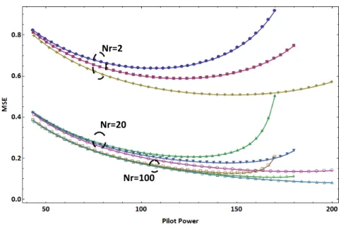
and 100 antennas. The circle indicates the optimal pilot and data power setting for the 2 antenna system with a sum power constraint of 250 mW. . . 16 3.4 The MSE as a function of the pilot power of a SIMO system withNr=2,20,100
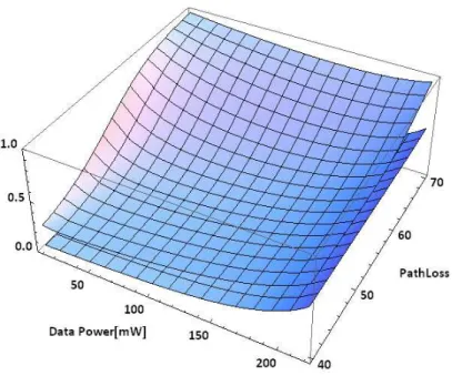
antennas respectively, for 3 different sum power constraints (200 mW, 225 mW and 250 mW). As the number of antennas increases, the optimal pilot power increases. . . 17 3.5 The MSE as a function of the data power and the distance dependent path loss of a
sum power constrained (250 mW) SIMO system withNr=2 andNr=100 antennas.
For Nr=2, as the path loss increases, the data power level that minimizes the MSE
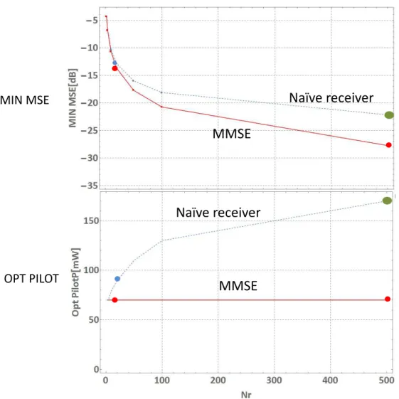
increases. However, this effect is not visible forNr=100. . . 18 4.1 MSE as the function of the pilot powerPp assuming a fixed pilot+data power budget
withNr=20 andNr=500 number of antennas when using the naïve receiver and the MMSE receiver. . . 31 4.2 The achievable minimum MSE and the optimum pilot power as the function of the
number of the base station antennas when employing the naïve receiver and the MMSE receiver. The dots in the figure correspond to the case ofNr=20 andNr=500 antennas. 32 5.1 Contour plot of the MSE achieved by specific pilot and data power settings of a SIMO
system withNr=20uncorrelatedreceiver antennas at a fix path loss position of 50 dB.
For example an MSE value less than 0.03 can be reached by setting the pilot power budget toτpPp≥70 mW and the data power P≥60 mW, or byPp ≥200 mW and P≥20 mW. We can see that with a total power budget of 250 mW, and with proper
pilot-data balancing, a minimum MSE that is clearly less than 0.03 can be reached. . . 43
x List of Figures 5.2 Contour plot of the MSE achieved by specific pilot and data power settings of a SIMO
system withNr=20correlatedreceiver antennas at a fix path loss position of 50 dB.
Compared with Figure 5.1, we can see that with similar sum power budget, the MSE value that can be reached is somewhat higher. For example, with a power budget of 250 mW, an MSE value that is less than 0.08 can be realized (τpPp=150 mW andP=100 mW). . . 44 5.3 Contour plot of the MSE as the function of the data power and the path loss
under a total power (250 mW) constraintwith Nr=20 uncorrelated antennas. For example, with the near optimal data power setting and MSE value of 0.14 can be
reached at 58 dB path loss. . . 45 5.4 Contour plot of the MSE as the function of the data power and the path loss
under a total power (250 mW) constraintwithNr=20 highly correlated antennas. For example, with the near optimal data power setting and MSE value of 0.14 can be
reached at 55 dB path loss. . . 46 6.1 Spectral efficiency (SE) in bps/Hz in log scale of block type channel estimation as a
function of the number of pilot time slots withNr=10 andNr=1000 antennas at the BS. With block type arrangement and EPA, allF=12 subcarriers in each of theT=14 time slots are dedicated to either pilot or data transmission withPtot=250 mW total transmit power shared equally in the frequency domain. TheTpthat maximizes spectral efficiency is clearly different with LS and MMSE estimations. . . 58 6.2 Spectral efficiency (SE) in log scale of comb type channel estimation as a function of
the number of pilot channels in the frequency domain withNr=10 andNr=1000 antennas at the BS. With comb type arrangement and EPA,Fp subcarriers (each with Ptot/Ftransmit power) are used to transmit pilot symbols in each of theT =14 time slots. TheFpthat maximizes spectral efficiency is clearly different with LS and MMSE estimations. . . 59 6.3 Optimum pilot power in mW as the function of the number of receive antennas at the
BS when using LS (upper curve) or MMSE (lower curve) channel estimation. With LS estimation, the optimum pilot power increases with the number of antennas, whereas with MMSE estimation, the optimum pilot power is constant (staying at 40% of the
total power budgetPtotin each time slot). . . 60 6.4 The spectral efficiency (SE) as the function of the number of receive antennas at the BS,
when employing LS (lower 2 curves) and MMSE (upper 2 curves) channel estimation.
In both cases, optimum pilot power allocation is compared with equal power allocation between pilot and data transmission. With LS estimation, optimum pilot power allocation gives large gains, whereas with MMSE estimation, this spectral efficiency
gain obtained by optimum pilot power allocation is less, although still significant. . . 61 6.5 Spectral efficiency with comb pilot arrangement and LS (lower) and MMSE (upper)
channel estimation as a function of the number of frequency channels and the total pilot power (out of thePtot) withNr=10 receive antennas. The pilot power that maximizes spectral efficiency is aroundPoptp =100 mW with both LS and MMSE. . . 62 6.6 Spectral efficiency with comb pilot arrangement and LS (lower) and MMSE (upper)
channel estimation as a function of the number of frequency channels and the total pilot power withNr=1000 receive antennas. The pilot power that maximizes spectral efficiency is aroundPpopt=200 mW with LS and 100 mW with MMSE estimation. . . . 62 7.1 Cumulative distribution function of the squared error in a single user MIMO scenario
when the path loss between the UE and the BS is set to 40 and 50 dB when using the naïve receiver, the MMSE receiver and the receiver which has access to the perfect CSI withNr=500 antennas. . . 77
List of Figures xi 7.2 Comparing the performance of the naïve and the MMSE receiver in the case of
correlated (solid lines) and uncorrelated (dashed lines) antennas (withNr=4,16,64). . . 78 7.3 Comparing the MSE performance of the naïve and MMSE receivers with that of a
receiver that uses perfect CSI. As the pilot power increases, the MSE achieved by the receiver that uses perfect CSI increases, because due to the sum power constraint the transmit power available for the data symbols decreases. . . 79 7.4 Spectral efficiency as a function of the employed pilot symbolsτp. In this example, the
number of users in MU MIMO system is set equally toτp, that is I assume that the
number of users that can be spatially multiplexed equals the pilot sequence length. . . 80
List of Tables
1.1 System Configuration and Main Results of Chapters 3-7 . . . 4
4.1 System Parameters . . . 30
5.1 System Parameters . . . 42
7.1 System Parameters . . . 76
Summary
As an engineer and researcher, I have been dealing with the research, standardization and industrial- ization of wireless communication systems since the late 90’s. Specifically, I have been witnessing and contributing to the evolution of the 3rd, 4th and currently to the 5th generation of cellular networks.
The impact of this evolution on the society, public administration, businesses and individuals has been profound and played a key role in defining the information age and shaping the fully connected societies.
Indeed, the technology footprint of cellular networks has lead to unprecedented economies of scale, which, in turn resulted in a rapid growth of technology solutions that enable them to operate with high spectral and energy efficiency in a great number of spectrum bands.
My contributions to the advances of cellular technologies lie in the fields of radio resource management and signal processing for multi-antenna systems, and specifically in the areas of channel estimation and receiver design. In particular, my contributions as a researcher are threefold: (i) conducting research for the purpose of proposing channel estimation and receiver designs that are superior to their state-of-the-art counterparts, (ii) identifying the necessary changes in communication standards that ensure the inter- operability of such novel designs and (iii) developing suitable methodology for the performance analysis of the proposed channel estimation and receiver techniques. The results of these efforts include research papers in internationally recognized journals and book chapters, communication standards specifically developed for the inter-operability of cellular systems and more than 40 internationally granted patents that are deployed cellular systems around the world.
In this thesis, I develop methodology and techniques to develop receiver algorithms that are optimal in terms of minimizing the mean squared error of the received data symbols in the presence of the estimation errors of the prevailing wireless channels through which communication takes place. The proposed methodology and techniques enable me to prove that the state-of-the-art receiver structures are suboptimal in the presence of wireless channel estimation errors, while the proposed receivers are optimal in terms of minimizing the symbol errors at multi-antenna receivers. I also developed methodology that enables the exact analysis of the symbol errors as functions of the resources used for obtaining channel estimates at the wireless receiver and transmitting data through the wireless channel.
These methods have lead to channel estimation techniques and receiver algorithms that significantly improve the spectral and energy efficiency of multi-antenna cellular systems, and simplify the design of receiver algorithms when the number of deployed antennas at cellular infrastructure nodes increases over time.
Összefoglaló
A kilencvenes évek óta a vezetéknélküli távközlő rendszerek kutatásával, szabványosításával és ipari megvalósításával foglalkozom. Munkám során hozzájárultam a harmadik, negyedik és jelenleg az ötödik generációs celluláris rendszerek fejlődéséhez. E fejlődés jelentős hatást gyakorol társadalmunk szinte minden szegmensére, és meghatározó szerepet játszik az információs társadalom formálásában. A cel- luláris rendszerek széleskörű használata lehetővé tette e rendszerekben alkalmazott csúcstechnológiák gyorsan megtérülő kifejlesztését és gazdaságos bevezetését. Ezeknek a mérnöki megoldásoknak köszön- hetően a celluláris hálózatok milliók számára teszik lehetővé az Internetes szolgáltatások elérését.
Kutatási területem a vezetéknélküli távközlő rendszerek rádiós erőforrásainak menedzselését segítő algoritmusok, valamint az ilyen rendszerekben alkalmazható jelfeldolgozó módszerek. Specifikusan, e disszertáció eredményei hozzájárulnak a többantennás vezetéknélküli távközlő rendszerekben al- kalmazható csatornabecslő és jelvevő módszerek fejlesztéséhez, ezen módszerek szabványosításához valamint teljesítményelemzéséhez. E területeken elért eredményeimet nemzetközi konferenciákon és tudományos folyóiratokban valamit számos könyvfejezetben tettem közzé. A javasolt rádiós erőforrás- kezlő és többantennás rendszerekben alkalmazható jelfeldolgozó technikák ipari megvalósitását jelenleg több, mint negyven nemzetközi szabadalom védi.
Jelen disszertáció olyan módszereket és technikákat mutat be, melyek optimális többantennás vevők kifejlesztését teszik lehetővé, abban az értelemben, hogy a vett adatszimbólumok átlagos négyzetes hibája minimális. A disszertációban kidolgozott módszerekről bebizonyítom, hogy a jelenleg alka- lmazásban lévő vevőalgoritmusok szuboptimálisak, azaz nem minimalizálják a vett adatszimbólumok becslési hibáját olyan esetekben, melyekben a rádiós csatorna állapota a vevő számára nem pontosan ismert. Az általam javasolt módszer újdonsága, hogy a csatornabecslést és a küldött adatszimbólumok dekódolását együttesen kezeli. Ezáltal lehetővé válik a csatornabecslésre és az adatküldésre szánt rádiós erőforrások együttes kezelése és optimalizálása. Olyan matematikai módszereket dolgoztam ki, melyek ezen együttes csatornebecslő - jelvevő módszerek pontos, zárt képletekkel történő elemzését teszik lehetővé, és ezáltal betekintést nyújtanak az antennák számanak, az alkalmazott adóteljesítménynek és más mérnöki paramétereknek a kommunikáció minőségére és spektrumhatékonyságára gyakorolt hatásának az elemzésére.
A disszertációban javasolt módszerek összességükben nagyban javítják a többantennás celluláris rendszerek spektrális és rádiós erőforrás hatékonyságát és a vezetéknélküli csatornán történő kommu- nikáció minőségét.
Acknowledgments
First and foremost I would like to thank Miklós Telek for the many years of joint works, support and encouragement. It is a privilage to be one of his disciples in the broad field of mathematical modeling and performance analysis. I am also grateful for the support, encouragement and technical discussions and the many pieces of advice by László Pap and Sándor Imre during the preparation phase of this dissertation.
I gratefully acknowledge the numerous pieces of advice and encouragement by Gábor Horváth.
I am grateful to Tamás Henk, Gyula Sallai, József Bíró, Tibor Cinkler, Edit Halász and Do Van Tien for their selfless and wholehearted encouragement and support of all sorts since I graduated at the Department of Mediainformatics in the late 90’s. I also thank Norbert Reider and András Rácz for their encouragement, help and the discussions on various technical topics.
Finally, I would like to thank the incredible support, continuous encouragement and the uncountable pieces of advice of all possible kinds by my family, including my mother, my wife Viktória and my children Laura and Sebastian.
Chapter 1
Introduction
1.1 Technological Motivation
In this section I review some of the relevant literature in the areas of information theoretical aspects of wideband communications, Multiple Input Multiple Output (MIMO) transceiver design, pilot based channel estimation techniques and specifically techniques to mitigate the affects of pilot contamination (PC) and Channel State Information (CSI) errors. I also point out my contributions to this line of research.
1.1.1 Information Theoretical Aspects of Wideband Communications and Capacity Analysis
An important insight from the works reported in [1] and [2] is that there is a continuum between the extremes of communicating in non-coherent (without CSI availability) and coherent (perfect CSI) fashions over wireless channels in terms of the achieved spectral efficiency. Specifically, communicating over a completely unknown channel is subject to a penalty of the channel uncertainty, sometimes in the form of training costs. On the one hand, this penalty depends on the knowledge the receiver has of the channel and on the channel’s rate of change. On the other hand, reducing this penalty by sending over only a fraction of the available degrees of freedom results in a loss of spectral efficiency.
In practice, the channel coherence time might be long enough to both estimate the fading coefficients and use such estimates to communicate coherently after the estimation period, as well as to achieve performance close to the fully coherent case (as emphasized in [3]).
Reference [2] studies the connection between the channel uncertainty penalty and the coherence length of the channel in MIMO systems. A key observation is that in the low signal-to-noise ratio (SNR) regime, estimating the channel at the receiver may not be possible and hence communication may be desirable without training. More exactly, if the channel coherence length is above a certain antenna- and SNR-dependent threshold, the noncoherent and coherent capacities become the same in the low-SNR regime.
The above results suggest that, depending on the SNR and the number of antennas, there may be a large gap between the coherent and noncoherent extremes in terms of achievable spectral efficiency, and channel learning is key in bridging this gap. Therefore, it is interesting to consider the ultra- wideband (UWB) regime and focus on the case when training signals are used for channel estimation at the receiver. The capacity of this scheme is studied in [4] to investigate the impact of multipath sparsity on achieving coherent capacity. The key results of that paper are a lower bound on the capacity of the training-based communication scheme and the coherence level that can be achieved, and the insights into the impact of channel sparsity on the achievable capacity in the UWB regime.
The work in [5] studies the impact of channel state feedback on the achievable rates in sparse wideband channels. A key insight is that a partial and/or limited feedback scheme, where only one bit per independent degree-of-freedom (DoF) is available at the transmitter, can nearly achieve the performance of a system in which perfect CSI is available at the transmitter. References [6] and [7] focus on acquiring channel state information at the transmitter in multi-user systems where the feedback from each user terminal must be limited. It is shown that the combination of long term channel statistics and instantaneous norm feedback provides sufficient information at the transmitter for efficient scheduling, beamforming and link adaptation in wide-area scenarios. More recently, the work in [8] considers a
2 1 Introduction case in which a transmitter with two antennas broadcasts to two single-antenna users. It is assumed that the two receiving users have perfect channel information, whereas the transmitter has only statistical information of each user’s link (covariance matrix of the vector channel). The paper focuses on the design of beamforming vectors that depend on such statistical information and maximize the ergodic sum-rate delivered to the two users.
1.1.2 Multiple Input Multiple Output Transceiver Design
Reference [9] deals with robust MIMO precoding design with deterministic imperfect channel state information at the transmitter channel state information at the transmitter (CSIT) such that the worst- case received SNR is maximized, or the worst-case error probability is minimized. Reference [10] is concerned with the design of linear MIMO transceivers that are robust to CSI perturbations at both sides of the link that is to errors in CSIT and channel state information at the receiver channel state information at the receiver (CSIR). In that work, the design of the transceiver is based on minimizing the average sum MSE of all data streams and users. That paper assumes a perturbation error (modelled as a Gaussian additive term), but this CSI error is not controlled by pilot power or the training scheme.
Therefore, the pilot-data trade-off is not considered in that paper. The model used in [11] builds on the uplink (UL)-downlink (DL) duality in sum MSE under imperfect CSI. In that work, the imperfectness of the channel knowledge is taken into account in the joint minimum mean squared error (MMSE) design.
The sum MSE minimization problem for the UL and DL is subject to power constraints. However, the aspect of pilot power is not considered, and the MSE is not derived as a function of the pilot power under a constrained pilot-data budget.
1.1.3 Channel Estimation and the Pilot-to-Data Power Ratio
The seminal work reported in [12] evaluates the difference between the mutual information when the receiver has only an estimate of the channel and when it has perfect knowledge of the channel. Upper and lower bounds are established on this difference and are related to the variance of the channel measurement error. In [13] it is shown how training based channel estimation affects the capacity of the fading channel, recognizing that training imposes a substantial information-theoretic penalty, especially when the coherence intervalTis only slightly larger than the number of transmit antennas or when the SNR is low. In these regimes, learning the entire channel is highly suboptimal. Conversely, if the SNR is high, andT is much larger thanM, training-based schemes can come very close to achieving capacity.
Therefore, the power that should be spent on training and data transmission depends on the relation betweenT andM. The work in [14] can be seen as a sequel of [13], taking into account intersymbol interference and the receiver technique (equalizer) used on the receiver side. However, none of these works consider the regularized MMSE receiver, and therefore the pilot power setting that minimizes the MSE of a regularized MMSE receiver is not discussed in these papers.
The Multi-user Multiple Input Multiple Output (MU-MIMO) setting is the focus of [15], in which the coherence interval ofTsymbols is expended for channel training, channel estimation, and precoder computation for DL transmission. Specifically, the optimum number of terminals in terms of the DL spectral efficiency is determined for a given coherence interval, number of base station antennas, and DL/UL signal-to-interference-plus-noise ratio. There is no receiver design involved and the pilot-to-data power trade-off is out of the scope of the optimization process.
Reference [16] investigates the optimization of the pilot overhead for single-user wireless fading channels, and the dependencies of this pilot overhead on various system parameters of interest (e.g.
fading rate, SNR) are quantified. By finding an expansion of the spectral efficiency for the overhead
1.2 Dissertation Structure 3 optimization in terms of the fading rate around the perfect-CSI point, the square root dependence of both the overhead and the spectral efficiency penalty is clearly identified.
1.1.4 Contributions of the Dissertation
In this dissertation, I consider the uplink of Single-User Multiple Input Multiple Output (SU-MIMO) and MU-MIMO systems that use pilot based estimation techniques to acquire CSIR and aim at minimizing the MSE of the received data symbols. To this end, in this rather general setting, the dissertation addresses the key design aspects of designing the optimal receiver structure and the finding optimal Pilot-to-Data Power Ratio (PDPR) an MMSE receiver for data reception.
My contributions to the existing literature are as follows:
• I derive the actual MMSE receiver that – in contrast to the classical or naive formula – minimizes the MSE of the estimated uplink data symbols in the presence of PDPR dependent estimation errors.
• I derive a closed form exact expression for the MSE, as a function of not only the PDPR but also the number of antennas. This exact formula allows me to arrive at the key insight that employing the actual MMSE gives large gains as the number of antennas grows large.
• For the case of uncorrelated receive antennas at the base station (BS), I give a closed form expression for the MSE of the estimated data symbols and for the pilot power that minimizes this MSE.
• For the case of correlated receive antennas at the BS, I identify the regularized MMSE receiver structure, and give closed form expressions for the achieved MSE.
• I derive a closed form for MSE of the equalized data symbols for arbitrary correlation structure between the antennas by allowing any covariance matrix of the uplink channel. This form is powerful, because it considers not only the pilot and data transmit power levels and the number of receive antennas at the base station as independent variables, but it also explicitly takes into account antenna spacing and the statistics of the angle-of-arrivals (AoAs), including the angular spread as a parameter.
For example, the methodology enables me to study the impact of the PDPR on the UL performance for the popular 3GPP spatial channel model often used to model the wireless channels in cellular systems. The closed form formula takes into account the impact of number of antennas, AoA and angular spread on the MSE and thereby on the PDPR that minimizes the MSE.
• I derive closed forms for both the uplink data MSE and spectral efficiency taking into account the constraints of the comb and block type pilot arrangements. As a major difference with respect to previous works, this closed form result allows me to find the close-to- optimum number of pilot symbols and pilot power for a generic channel estimation method. In particular, I compare Least Square (LS) and MMSE channel estimation in block-type and comb-type pilot arrangement, for a BS that employs a large number of antennas.
These results allow me to study numerically the gains of using the regularized MMSE receiver and optimal pilot power levels over schemes that use the naive receivers and/or suboptimal pilot power levels.
A key insight is that the pilot power that minimizes the MSE does not depend on the number of antennas, but heavily depends on the path loss between the BS and the mobile terminal.
1.2 Structure of the Dissertation
Due to the complexity of MU-MIMO systems and the inherent trade-offs associated with CSI acquisition and data reception, different system configurations are appropriate in specific deployment scenarios.
Therefore, in this dissertation, I consider a wide range of system configurations, as specified in Table 1.1.
4 1 Introduction Table 1.1 System Configuration and Main Results of Chapters 3-7
Chapter Basic System
Setup
Receiver Struc- ture
Antenna Correla- tion
Comment Main Results Chapter 3 single user naive receiver uncorrelated
antennas LS channel estima- tion, single pilot symbol
Theorem 3.1
Chapter 4 multiuser naive and true
MMSE uncorrelated
antennas LS channel estima-
tion, pilot sequence Theorem 4.3.3, Theorem 4.5.1 Chapter 5 single user naive receiver correlated anten-
nas LS and MMSE
channel estimation, pilot sequence
Theorem 5.5.1
Chapter 6 single user naive receiver uncorrelated
antennas LS and MMSE
channel estimation, comb and block type pilot symbol arrangements
Theorem 6.5.1, Theorem 6.5.2
Chapter 7 multiuser naive and true
MMSE correlated anten-
nas LS and MMSE
channel estimation Theorem 7.5.1, Propositions 7.5.2 and 7.5.3
Chapter 2 considers a simplified system as compared with real MU-MIMO systems deployed in practice. Despite this simplification in terms of both channel estimation and data reception, the abstract model of Chapter 2 and the derived results on the MSE of the received data symbols provide valuable insights, and serve as a starting point for the more realistic system models developed in the subsequent chapters. The main result of this chapter is a closed form expression for the MSE in a single user SIMO system in the case of uncorrelated antennas.
Chapter 3 considers a system, in which multiple users share the same time-frequency resource and facilitate CSI acquisition at the BS by transmitting orthogonal pilot sequences in the code domain. The main result of this chapter is the derivation of the receiver that minimizes the MSE of the uplink received data symbols in the presence of MU-MIMO interference and CSI errors at the receiver. As I will point out, the literature uses the terminology of MMSE receiver for receivers that, in fact, do not minimize the MSE unless perfect CSI is available at the receiver. To distinguish the true MMSE receiver from the receiver that requires perfect CSI, in this dissertation I use the terms naive receivers and MMSE receivers, where the latter refers to the receiver that does not require perfect CSI to minimize the MSE, as it is detailed in Chapter 3.
Chapter 4 relaxes the assumption on uncorrelated antennas, and thereby it aims at analyzing a significantly more realistic model than that of the preceding chapters. However, allowing for arbitrary antenna correlation structures by taking into account antenna spacing and AoA conditions of antenna arrays used in practice makes the analysis more involved. The main result of this chapter is the closed form derivation of the MSE taking into account antenna correlation.
Chapter 5 assumes perfectly uncorrelated antennas, but allows for comb and block type pilot ar- rangements. The results of this chapter include closed form formulas for the MSE of the received data symbols, and approximate closed form formulas for the spectral efficiency of the system. The results of this chapter are important for selecting the best channel estimation scheme and pilot symbol pattern in systems using moderate or large number of antennas.
Finally, Chapter 6 develops a model that can capture the characteristics of MU-MIMO systems in which antenna correlation cannot be ignored and uses the MMSE receiver. This chapter generalizes the results of Chapter 3 by allowing for correlated antennas. It also proves a result that was first conjectured, based on numerical experiments in Chapter 3. This result states that the optimal pilot power that minimizes the MSE is independent of the number of receive antennas when the system uses the true MMSE receiver. This result is an important difference as compared with the naive receiver, whose optimal pilot power is sensitive to the number of antennas, and have to be reconfigured when increasing the number of antennas at deployed BSs.
Chapter 2
Background
2.1 The Evolution of Multi-Antenna Systems: From Single User to Massive Multi-user Multiple Input Multiple Output Systems
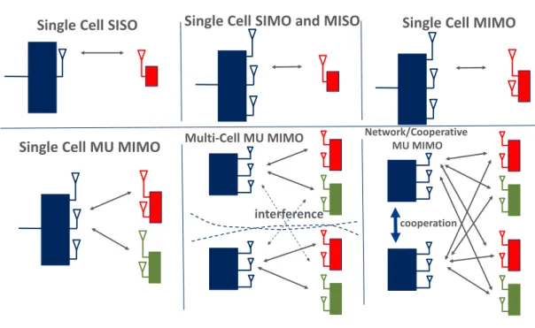
Conventional communication systems equipped with a a single transmit antenna and a single receive antenna are called Single Input Single Output (SISO) communication systems (Figure 2.1, upper left).
This intuitively clear terminology explicitly refers to a signal model that involves the convolution of the complex impulse response of the wireless channel (typically represented as a random variable h) and the single inputxto model the single outputy:
y=h?x+n, (2.1)
where n is complex baseband additive white Gaussian noise. The above equation is for a single realization of the complex single outputy.
The value of multiple antenna systems as a means to improve communications, including improving the overall system capacity and transmission reliability, was recognized in the early ages of wireless communications. Specifically, adaptive transmit or receive beamforming by means of employing multiple antennas either at the transmitter or the receiver roots back to classic papers that appeared in the 1960s and 1970s [17, 18, 19]. In particular, Widrowet al.described the Least Mean Square (LMS) adaptive antenna array, which is a technique to adaptively determine the weights that are derived from the received signal to minimize the MSE between the received signal and a reference (pilot) signal [17, 19]. Applebaum proposed a multiple antenna array structure that adaptively suppresses sidelobe energy when the desired signal’s AoA is known, such as in a radar system.
Starting from the 1980’s, there has been a renewed and increased interest in employing multiple antenna techniques in commercial systems, particularly mobile and cellular systems, where multipath and unintentional interference from simultaneously served users was the main and increasing concern [20].
However, it was not until the cost of digital signal processing was dramatically reduced and commercial wireless systems matured in the late 1990s that adaptive beamforming became commercially feasible, and large scale industrial interest has started to take off.
While traditional SISO systems exploit time- or frequency-domain processing and decoding of the transmitted and received data, the use of additional antenna elements at the cellular BS or user equipment (UE) side opens up the extra spatial dimension to signal precoding and detection. Depending on the availability of multiple antennas at the transmitter and the receiver, such techniques are classified as SIMO, multiple input single output (MISO) or MIMO (Figure 2.1, upper middle and upper right).
Specifically, space-time and space-frequency processing methods in SIMO, MISO and MIMO systems make use of the spatial dimension with the aim of improving the link’s performance in terms of error rate, data rate or spectral and energy efficiency [19].
In the context of cellular networks, for example, in the scenario of a multi-antenna enabled BS communicating with a single antenna UE, the UL and DL are referred to as SIMO and MISO respectively.
When a multi-antenna terminal is involved, a full MIMO link may be obtained, although the term MIMO is sometimes also used in a collective sense including SIMO and MISO as special cases.
A MIMO system, in which the transmitter and receiver are equipped with M and N antennas respectively, is conveniently characterized by the multi-dimensional version of (2.1) as follows:
6 2 Background
interference cooperation
Single Cell SISO Single Cell SIMO and MISO Single Cell MIMO
Single Cell MU MIMO
Multi-Cell MU MIMO Network/Cooperative MU MIMOFig. 2.1 The evolution of multiple antenna systems from single cell single input single output transmissions to cooperative network multiple input multiple output transmissions.
y= H
|{z}
N×M
x
|{z}
M×1
+ n
|{z}
N×1
∈ CN×1, (2.2)
wherexandyrepresent the complexM andN dimensional input and output vectors of the MIMO system respectively.
While a point-to-point multiple-antenna link between a BS and a UE is referred to as SU-MIMO, MU-MIMO features several UEs communicating simultaneously using the same frequency- and time- domain resources (Figure 2.1, lower left). By extension, considering a multi-cell system, neighboring BSs sharing their antennas and forming a virtual MIMO system to communicate with the same set of UEs in different cells are called cooperative multi-point (CoMP) or network MIMO transmission/reception (Figure 2.1, lower middle and lower right).
Multiple antenna techniques, as illustrated by Figure 2.1 offer (the combinations of) three advantages over traditional SISO systems:
• Diversity gain: The diversity gain corresponds to the mitigation of the effect of multipath fading, by means of transmitting and/or receiving over multiple wireless channels created by the multiple antennas on the transmit and/or receive sides of the communication link.
• Array gain: The array gain corresponds to a spatial version of the well-known matched-filter gain achieved by time-domain receivers.
• Spatial multiplexing gain: The spatial multiplexing gain refers to the ability to send multiple data streams in parallel and to separate them on the basis of their spatial signature. The spatial multiplexing gain is a particularly attractive gain of MIMO systems over SISO systems, because MIMO data stream multiplexing does not come at the cost of bandwidth expansion and can therefore yield drastic spectral efficiency gains.
As we shall see, the gains associated with multi-antenna systems strongly depend on the availability of CSI – the matrixHin (2.2) – at the transmitter and the receiver, which motivated the research and standardization communities to develop resource efficient techniques that enable the acquisition of CSIT
2.2 Channel State Information Acquisition and Transceiver Design: Major Challenges in Multiple Input Multiple Output Systems7 and CSIR. Due to their great impact on the achievable gains, these acquisition techniques form an important part of MIMO systems, as discussed in more detail in the next section.
Due to the advances in digital signal processing, antenna theory and the commercial success of MIMO, and in particular, MU-MIMO systems, the research community has been investigating the characteristics of large scale antenna systems, in which the cellular BS is equipped with a great number of antennas. Indeed, evolving wireless standards are expected to support the deployment of several tens or even hundreds of transmit and receive antennas at infrastructure nodes and over ten transmit and receive antennas at commercial UEs. It is worth noting that in the asymptotic regime of such large scale or massive MIMO systems, it turns out that the lack of accurate CSI is the main cause of performance saturation, besides hardware impairments. Therefore, scalable and resource efficient CSI acquisition techniques have been and continues to be in the focus of the MIMO community ever since the large commercial deployments of such systems have started.
2.2 Channel State Information Acquisition and Transceiver Design: Major Challenges in Multiple Input Multiple Output Systems
As noted, the spectral and energy-efficient operation of wireless systems in general, and multiple antenna systems in particular, relies on the acquisition of accurate CSIT and CSIR [21]. The main reasons for this are that (1) transmitters of modern wireless systems adapt the transmitted signal characteristics to the prevailing channel conditions and (2) the effect of the channel on the transmitted signal must be estimated in order to recover the transmitted information. As long as the receiver accurately estimates how the channel modifies the transmitted signal, it can recover the signal from the impacts of the wireless channel.
In practice, pilot signal-based data-aided techniques are used not only due to their superior performance in fast fading environments, but also due to their cost efficiency and inter-operability in commercial systems. Consequently, channel estimation methods have been studied extensively and a large number of schemes, including blind, data-aided, and decision-directed non-blind techniques, have been evaluated and proposed in the literature [22, 23, 24].
As the number of antennas at the BS and the simultaneously served users grows large, it is desirable to have pilot based schemes that are scalable in terms of the required pilot symbols and provide high quality CSI for UL data detection and DL precoding. To this end, MU-MIMO systems employing a large number of antennas typically rely on channel reciprocity and employ uplink pilots to acquire CSI at BSs. Although solutions for non-reciprocal systems (such as systems operating in frequency division duplex (FDD) mode) are available [25], it is generally assumed that massive MIMO systems can advantageously operate in time division duplex (TDD) mode exploiting channel reciprocity [26, 27].
Pilot reuse generally causes contamination of the channel estimates, which is known as PC or pilot pollution. As there are a large number of channels to be estimated in MU-MIMO and massive MIMO systems, accurate CSI acquisition scaling with the number of BS antennas becomes a significant challenge due to the potentially limited number of pilots available. Indeed, PC limits the performance gains of non-cooperative MU-MIMO systems [26, 28]. Specifically, PC is known to cause a saturation effect in the signal-to-interference-plus-noise ratio (SINR) as the number of BS antennas increases to a very large value. This is in contrast to the PC exempt scenario where the SINR increases almost linearly with the number of antennas [28]. It is therefore clear that the trade-offs associated with the resources used for pilot signals and those reserved for data transmission is a key design aspect of modern wireless communication systems.
8 2 Background
Trade-Offs:
Higher pilot
power
Better channel estimate SNR degradation for data;Increased effect of pilot contamination
More pilot symbols
Better channel estimate;
Less aggressive pilot reuse;
More users for MU multiplexing
Less data symbols
Block type allocationComb type alloaction
Time-frequency spaced pilot allocation
Pilot csatorna Adatcsatorna
Pilot csatorna
Pilot subcarrier
Adatcsatorna
Data subcarrier Frequency
Frequency
Frequency
Pilot subcarrier Data subcarrier Pilot subcarrier Data subcarrier
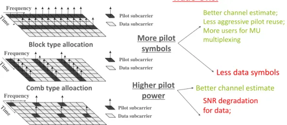
Fig. 2.2 Trade-offs associated with channel estimation, reference (pilot) signal design in MU-MIMO systems
2.3 Fundamental Trade-Offs in the Design of Multi-user Multiple Input Multiple Output Systems
Although pilot-based CSI acquisition is advantageous in fast fading environments, its inherent trade-offs must be taken into account when designing channel estimation techniques for various purposes. These purposes include demodulation, precoding or beamforming, spatial multiplexing and other channel- dependent algorithms such as frequency selective scheduling or adaptive modulation and coding scheme (MCS) selection [29, 30, 15]. The inherent trade-offs between allocating resources to pilot and data symbols include the following, as illustrated in Figure 2.2:
• Increasing the power, time, or frequency resources to pilot signals improves the quality of the channel estimate, but leaves fewer resources for uplink or downlink data transmission [29, 30, 15].
• Constructing long pilot sequences (for example, employing orthogonal symbol sequences such as those based on the well-known Zadoff-Chu sequences in Long Term Evolution (LTE) systems) helps to avoid tight pilot reuse in multi-cell systems), helps to reduce or avoid inter-cell pilot interference.
This is because long pilot sequences enable to construct a great number of orthogonal sequences and, consequently, help avoid pilot reuse in neighbor cells, and thereby address the root cause of PC. On the other hand, spending a greater number of symbols on pilots increases the pilot overhead and might violate the coherence bandwidth [15, 16].
• Specifically in MU-MIMO systems, increasing the number of orthogonal pilot sequences may increase the number of spatially multiplexed users at the expense of spending more symbols when creating the orthogonal sequences [29, 30].
In particular, increasing the pilot power increases the SNR of the received pilot signal, and thereby improves the quality of channel estimation in terms of the MSE of the channel estimate [31]. Unfortu- nately, increasing the pilot power may also lead to the SNR degradation of the data signals, and may exacerbate the PC problem in multi-cell scenarios [32]. In addition to these inherent trade-offs, the arrangement of the pilot symbols in the time, frequency, and spatial domains have been shown to have
2.3 Fundamental Trade-Offs in the Design of Multi-user Multiple Input Multiple Output Systems 9 a significant impact on the performance of MU-MIMO and massive MIMO systems in practice, see for example [29, 30, 33].
Chapter 3
The Pilot-to-Data Power Ratio in Single User Systems
3.1 Introduction
In this chapter I consider a single input multiple output SIMO system in which the Mobile Station (MS) balances its PDPR, while the BS uses LS channel estimation to initialize a linear MMSE equalizer. The objective of this chapter is to derive a closed form for the MSE of the equalized data symbols. To obtain engineering insight into the inherent pilot-data trade-off as the number of antennas increases at the BS, my objective is to derive an MSE formula that includes not only the pilot and data transmit power levels as independent variables, but also the number of receive antennas at the base station (Nr). This formula allows me to study the impact ofNron the MSE and thereby on the PDPR that minimizes the MSE. To the best of my knowledge the MSE formula as well as the insights obtained in the numerical section of this chapter are novel.
3.2 System Model
I consider the uplink transmission of a SIMO single cell multi-user wireless system, in which users are scheduled on orthogonal frequency channels. It is assumed that each mobile station (MS) employs an orthogonal pilot sequence, so that no interference between pilots is present in the system. This is a common assumption in massive multi-user MIMO systems in which a single MS may have a single antenna [26]. Since the channel is quasi-static frequency-flat within each transmission block, it is equivalent to model the whole pilot sequence as a single symbol per resource block with powerPp, while each data symbol is transmitted with powerP. The BS estimates the channelh(column vector of dimension Nr, where Nr is the number of receive antennas at the BS) by employing LS channel estimators to initialize linear MMSE equalizers.
3.2.1 Channel Estimation Model
Each MS transmits an orthogonal pilot symbolxjthat is received by the BS. Thus, the column vector of the received pilot signal at the BS from the jthMS is:
ypj =q
Ppjαjhjxj+np, (3.1)
where it is assumed thathjis a circular symmetric complex normal distributed vector with mean vector 0and covariance matrixCj (of size Nr), denoted ashj∼ CN(0,Cj),αj accounts for the propagation loss,np∼ CN(0, σ2I)is the contribution from additive Gaussian noise and the pilot symbol is scaled as
|xj|2=1,∀j. Since I assume orthogonal pilot sequences, the channel estimation process can be assumed independent for each MS, and I can therefore drop the index j. With a LS channel estimator, the BS estimates the channel based on (3.1) assuming
hˆ= yp
√ Ppαx,
12 3 The Pilot-to-Data Power Ratio in Single User Systems that is:
hˆ=h+ np
√
Ppαx; |x|2=1. (3.2)
It then follows that the estimated channelhˆ is distributed as follows:
hˆ∼ CN(0,R), (3.3)
withR,E( h ˆˆhH)
=C+Pσp2α2 I.
Further, it follows that the channel estimation errorw,hˆ−h is also normally distributed with a covariance inversely proportional to the employed pilot power:
w∼ CN(0,Cw); Cw, σ2 Ppα2 INr.
Equations (3.2)-(3.3) imply thathandhˆare jointly circular symmetric complex Gaussian (multivariate normal) distributed random variables [34], [35]. Specifically, recall from [34] that the covariance matrix of the joint probability density function (PDF) is composed by autocovariance matricesCh,h,Ch,ˆhˆand cross covariance matricesCh,hˆ,Ch,hˆ as
"
Ch,h Ch,hˆ Ch,hˆ Ch,ˆhˆ
#
=
"
C C C R
# , andR=C+Cw.
3.2.2 Determining the Conditional Channel Distribution
From the joint PDF ofhandhˆI can compute the following conditional distributions.
Result 3.2.1 Given a random channel realizationh, the estimated channelhˆ conditioned tohcan be shown to be distributed as
(hˆ|h)∼h+CN(0,Cw). (3.4)
Result 3.2.2 The distribution of the channel realizationh conditioned to the estimatehˆ is normally distributed as follows:
(h|h)ˆ ∼D ˆh+CN 0,Q
, (3.5)
whereD=CR−1andQ=C−CR−1C.
The proofs of these results are provided in the Appendix of this chapter.
To capture the tradeoff between the pilot and data power, I need to calculate the mean square error of the equalized data symbols. To this end, let us consider an equalization model in the next subsection.
3.2.3 Equalizer Model based on the Least Square Channel Estimator
TheNrdimensional data signal received by the BS is y=α√
Phx+n, (3.6)
3.3 Determining the Unconditional Mean Squared Error 13 where|x|2=1. I assume that the BS employs a naive MMSE equalizer, where the estimated channel (3.2) is taken as if it was the actual channel:
G=α√
PhˆH(α2Ph ˆˆhH+σ2INr)−1. (3.7) Under this assumption, I state the following result as a first step towards determining the MSE.
Result 3.2.3 LetMSE(h,h)ˆ =Ex,n(
|Gy−x|2)
be theMSEfor the equalized symbols, given the real- izations ofhandh. It isˆ
MSE(h,h)ˆ =α2PGhhHGH−2α√
PRe[Gh]+σ2GGH+1. (3.8) The proof is presented in the Appendix. From this, my next result follows directly.
Result 3.2.4 LetMSE(h)ˆ =Eh|hˆ
(MSE(h,h)ˆ )
be theMSEfor the equalized symbols, given the estimated channel realizationh. It satisfiesˆ
MSE(h)ˆ =G
α2P(D ˆh ˆhHDH+Q)+σ2INr
GH−2α√
PRe{GD ˆh}+1. (3.9) The proof is presented in the Appendix of the chapter.
3.3 Determining the Unconditional Mean Squared Error
Based on the conditional MSE expression of the preceding section, I am now interested in deriving the unconditional expectation of the MSE. To this end, the following two lemmas turn out to be useful.
Lemma 3.1.Given a channel estimate instanceh, the MMSE weighting matrixˆ G, as a function of the number of receive antennas at the base station (Nr) can be expressed as follows
G= α√ P
khkˆ 2α2P+σ2 hˆH, (3.10)
wherekhˆk2=hˆHhˆ=PNr i=1|hˆi|2. The proof is presented in the Appendix.
Using this simple expression ofGI can further simplify the conditional expectation of the MSE of the MMSE equalized data symbols.
Lemma 3.2.When assuming independent channel distributions with identical variances, that is the channel covariance matrix is diagonal in the form ofC=%I, where%∈R+, then the covariance matrices D,QareD=dI,Q=qIwithd=%(%+Pσp2α2)−1,q=%(1−d)and(3.9)simplifies to
MSE(h)ˆ =1− 2khkˆ 2dα2P
khkˆ 2α2P+σ2+ khkˆ 2α2P khˆk2α2P+σ22 ·f
khˆk2d2α2P+qα2P+σ2g
. (3.11)
The proof is presented in the Appendix of this chapter. After these preparations I can state the main theorem about the MSE.
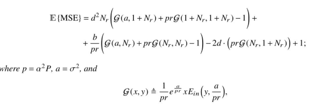
Theorem 3.1.The expected value of the mean square error of the equalized symbols is
14 3 The Pilot-to-Data Power Ratio in Single User Systems
E{MSE}=d2Nr G(a,1+Nr)+prG(1+Nr,1+Nr)−1
! + + b
pr G(a,Nr)+prG(Nr,Nr)−1
!
−2d·
prG(Nr,1+Nr) +1;
wherep=α2P,a=σ2, and
G(x,y), 1
prepra xEin y, a
pr ,
andEin(n,z),R∞
1 e−zt/tndtis a standard exponential integral function which is commonly available in numerical programming environments (e.g., it is called ExpIntegralE in Mathematica).
The proof is provided in the Appendix of the chapter.
It is important to note thatq andd carry the dependency on the pilot powerPp andpcarries the dependency on the data powerPinE{MSE}.
3.4 Numerical Results
Fig. 3.1 Contour plot of the MSE achieved by specific pilot and data power settings of a SIMO system withNr=2 receiver antennas. The diagonal line indicates the feasible region of a mobile station of a sum power level of 250 mW.
In this section I consider a single cell SIMO system and concentrate on the performance of a single mobile station (MS) scheduled on a flat fading frequency channel. Unless stated otherwise, I assume that the MS has a power budget of 24 dBm that needs to be shared between the pilot and data symbols, as described in Section 3.2.
3.4 Numerical Results 15
Fig. 3.2 Contour plot of the MSE achieved by specific pilot and data power settings of a SIMO system with 100 receiver antennas. The diagonal line indicates the feasible region of a mobile station of a sum power level of 250 mW.
Figure 3.1-3.2 are contour plots of the MSE of the equalized symbols as a function of the employed pilot and data transmit power levels when the number of receive antennas is Nr =2 and Nr =100 respectively. These figures indicate the pilot-data transmit power level pairs that maintain a given MSE.
For example, in Figure 3.1 we can see that the lowest MSE value that is feasible with a 250 mW power budget is 0.5. In contrast, Figure 3.2 shows that whenNr=100, the same power budget can maintain an MSE less than 0.1. From this figure it is also clear that the ’knee’ of the MSE curves is shifted toward much lower data power levels, which intuitively suggests a shift in the optimal PDPR. For example, the optimal MSE with 250 mW power budget is attained at aroundPp =145,P=105 on Figure 3.1 and aroundPp=215,P=35 on Figure 3.2.
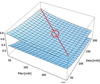
Figure 3.3 shows the impact of increasing the number of antennas at the base station from 2 to 100 in terms of the MSE performance as the function of the pilot and data transmit power. On the lower plane (Nr=100), the pilot power minimizing the MSE is shifted towards a higher value compared with the Nr=2 case (indicated with a circle) when I assume a power budget of 250 mW.
These results are reinforced by Figure 3.4 that shows the MSE as a function of the allocated pilot power under varying power budget (200mW, 225 mW and 250 mW) and assuming different number of receive antennas (Nr =2,Nr=20 and Nr=100). Here we can clearly see the tendency that as the number of the antennas grows large, the MS needs to allocate a smaller share of the total budget to data transmission and can ’afford’ a larger share of the budget for pilot transmission. This basic insight is in line with the classical observation by Marzetta predicting a diminishing data transmit power required for maintaining an SNR target [26].
Figure 3.5 shows the MSE as a function of the data power and the path loss for two antenna configurations (Nr=2 andNr=100). We can observe that the data power level that minimizes the MSE is not only dependent onNr, but also on the path loss. Specifically, for larger path loss (cell edge) users, more data power (i.e. less pilot power) minimizes the MSE than for cell center users. However, this effect becomes less pronounced as the number of antennas increases.
16 3 The Pilot-to-Data Power Ratio in Single User Systems
Fig. 3.3 The MSE of a SIMO system of 2 and 100 antennas. The circle indicates the optimal pilot and data power setting for the 2 antenna system with a sum power constraint of 250 mW.
3.5 Concluding Remarks
The main contribution of this chapter is the derivation of the MSE as the function of the employed pilot and data power levels as well as the number of receive antennas in SIMO systems. The numerical results provide two key insights. First, as the number of antennas at the base station increases, the MSE is minimized when a larger portion of the total transmit power budget is allocated for pilot transmission.
This result is in line with the results from massive MIMO systems that suggest that the required transmit energy per bit vanishes as the number of antennas grows large. Secondly, as the path loss between the MS transmitting the pilot and base station increases, a smaller portion of the power budget needs to be spent on the pilot power. This second effect becomes less pronounced as the number of antennas at the base station increases. My summary is therefore that the PDPR that minimizes the MSE of the equalized symbols heavily depends on both the number of antennas and the MS position within the cell.
An important future work is to investigate multicell systems, in which greater pilot power does not only imply lower available power for data transmission, but also a higher level of pilot contamination [26].
Therefore, these conclusions from the single cell analysis need to be reexamined in multicell systems.