Conference on Modelling Fluid Flow (CMFF’18) The 17th International Conference on Fluid Flow Technologies Budapest, Hungary, September 4-7, 2018
N ATURAL FREQUENCY EFFECT ON THE PATH OF AN ELASTICALLY SUPPORTED CIRCULAR CYLINDER
Dániel DOROGI
1, László BARANYI
21 Corresponding Author. Department of Fluid and Heat Engineering, Faculty of Mechanical Engineering and Informatics, University of Miskolc. 3515 Miskolc-Egyetemváros, Hungary. Tel.: +36 46 565 111, Fax: +36 46 565 168, E-mail: aramdd@uni-miskolc.hu
2 Department of Fluid and Heat Engineering, Faculty of Mechanical Engineering and Informatics, University of Miskolc. E-mail:
arambl@uni-miskolc.hu
ABSTRACT
Flow around a freely vibrating circular cylinder in two-degrees-of-freedom is investigated at low Reynolds numbers using two-dimensional numerical simulation. Systematic computations are carried out to investigate the effect of cylinder’s natural frequency fN on the oscillation amplitudes and aerodynamic force coefficients. The mass ratio and the structural damping coefficient values are fixed at m*=10 and ζ=0, respectively.
In addition to the typical distorted figure-eight motion, a raindrop-shaped path is also found whose range widens with increasing fN. Within this range the streamwise cylinder oscillation amplitude reaches higher values compared to figure-eight motions and the curves shift upwards with increasing fN. Sudden switches in the vortex structure occur near the upper boundaries separating the raindrop-shaped and distorted figure-eight motion domains. The root- mean-square (rms) values of lift plotted against U*St0 shift upwards in the raindrop-shaped motion range and downwards in the figure-eight motion range, while the rms of drag shifts to higher values in both regimes with increasing fN. The time-mean of lift coefficient jumps abruptly between two solutions. Using pre- and post-jump analysis it is shown that these solutions are mirror images of each other. Chaotic cylinder paths are observed when increasing the natural frequency over a critical value.
Keywords: circular cylinder, constant natural frequency, distorted figure-eight path, free vibration, raindrop-shaped path
NOMENCLATURE b [kg/s] damping
CD [-] drag coefficient, 2𝐹𝐷/(𝜌𝑈∞2𝑑) CL [-] lift coefficient, 2𝐹𝐿/(𝜌𝑈∞2𝑑) d [m] cylinder diameter, length scale D [-] dilation, non-dimensionalised by
U∞/d
FD [N/m] drag per unit length of cylinder FL [N/m] lift per unit length of cylinder fx,y [-] oscillation frequency in x or y
directions, respectively, non- dimensionalised by U∞/d
fv [1/s] vortex shedding frequency for a stationary cylinder
fN [1/s] natural frequency of cylinder k [N/m] spring stiffness
K [-] non-dimensional natural frequency, fNd2/ν
m [kg/m] mass of cylinder per unit length m* [-] mass ratio, 4m/(d2πρ)
p [-] pressure, non-dimensionalised by 𝜌𝑈∞2
R [-] radius, non-dimensionalised by d Re [-] Reynolds number, U∞d/ν
St0 [-] dimensionless vortex shedding frequency for a stationary cylinder, fvd/U∞
t [-] time, non-dimensionalised by d/U∞
u, v [-] velocities in x or y directions, non-dimensionalised by U∞
U∞ [m/s] free stream velocity, velocity scale U* [-] reduced velocity, U∞/(fNd)
x, y [-] Cartesian coordinates, non- dimensionalised by d
x0, y0 [-] cylinder displacement in x or y directions, non-dimensionalised by d
ζ [-] structural damping coefficient, 𝑏/(2√𝑚𝑘)
ν [m2/s] kinematic viscosity of the fluid ρ [kg/m3] fluid density
Subscripts and Superscripts L, D lift, drag
rms root-mean-square value mean time-mean values
1,2 on the cylinder surface, at the outer boundary of the domain
0 refers to cylinder response (x0, y0) or to a stationary cylinder (St0), fixed value 1. INTRODUCTION
Fluid flow around an oscillating bluff body (e.g.
circular cylinder) is an extensively investigated flow phenomenon. It has great importance e.g. in cases of risers, offshore structures or high slender buildings.
Vortex shedding from a circular cylinder often causes high amplitude vibrations of the structure, referred to as vortex-induced vibrations (VIV), which can lead to serious damage.
A freely vibrating cylinder model is commonly used in the literature. Although in reality the cylinder motion is two-degrees-of-freedom (2DoF), the vibration is often modelled by transverse-only motion. Khalak and Williamson [1] showed that the peak amplitude of the vibration strongly depends on the mass-damping parameter m*ζ, where m* is the mass ratio (the ratio of the mass of the cylinder and that of the displaced fluid) and ζ is the structural damping coefficient. They found that at low m*ζ values initial, upper and lower branches exist, where the upper branch is associated with the highest oscillation amplitude. In contrast, Feng [2] identified only initial and lower branches for high m*ζ values.
For 2DoF motion, Jauvtis and Williamson [3]
reported the existence of super-upper branch for m*<6. In their experiments the streamwise and transverse natural frequencies were identical (fNx = fNy). Sarpkaya [4] and Sanchis [5] carried out experiments where the natural frequency ratio was varied between fNx/fNy≅0.4–1.9.
Govardhan and Williamson [6] and Klamo et al.
[7] found that m*ζ is insufficient to predict the cylinder response, Reynolds number Re=U∞d/ν influences the flow also significantly, where U∞ is the free stream velocity, d is the cylinder diameter and ν is the kinematic viscosity of the fluid. Reduced velocity U*=U∞/(fNd) is another parameter which is used to characterise VIV. Although Re and U* are not independent variables, their separate effects are often investigated numerically. Singh and Mittal [8]
carried out numerical investigations using a 2DoF model with two sets of computations: (1) Re=100 and varying U* and (2) U*=4.92 and varying Re.
Two-branch cylinder response (initial and lower branches) was identified and the transition at the lower and upper boundaries of the synchronisation (or lock-in) domain showed hysteretic behaviour.
Similar results were obtained by Leontini et al. [9]
for 1DoF transverse-only cylinder motion.
Assuming that the natural frequency of the oscillating cylinder fN is constant, a linear relationship exists between Re and U*, Re=KU*, where K=fNd2/ν is the non-dimensional natural frequency value. Willden and Graham [10] carried out computations for K=20 analysing the effect of m*
on the cylinder response, with the cylinder restricted to move only in transverse direction. Bahmani and Akbari [11] investigated numerically the independent effects of m* and ζ on the vibration amplitude at K=17.9 for 1DoF oscillation. Prasanth and Mittal [12] studied 2DoF vibrations at K=16.6 and found that by reducing the numerical blockage ratio B (the ratio of the cylinder diameter and the height of the computational domain) the size of hysteretic loops diminishes and hysteresis completely disappears at a critical B value. Mittal and Singh [13], using a numerical approach, showed that by choosing K=3.1875, VIV occurs as low as Re=20, which is in the steady-state regime for a stationary cylinder.
The path of the moving cylinder is another area of interest. Mittal and Kumar [14] found figure-eight trajectories by varying U* at Re=325. Different cylinder paths were observed experimentally by Kang et al. [15], such as distorted figure-eight, egg- shaped and raindrop-shaped motions.
No information appears to be available in the literature on the flow around an elastically supported circular cylinder in 2DoF at high non-dimensional natural frequency values (K>20). In this study the effect of K>20 on the cylinder path and aerodynamic force coefficients are investigated using two- dimensional numerical simulations. Mass ratio and structural damping coefficient are fixed at m*=10 and ζ=0, respectively.
2. COMPUTATIONAL METHOD
The non-dimensional governing equations of the two-dimensional, incompressible, constant property, Newtonian fluid flow around a freely vibrating circular cylinder in 2DoF motion are the two components of the Navier-Stokes equations (written in a non-inertial system fixed to the moving body), the continuity equation and the pressure Poisson equation, which can be written as follows:
𝜕𝑢
𝜕𝑡 + 𝑢𝜕𝑢
𝜕𝑥+ 𝑣𝜕𝑢
𝜕𝑦= −𝜕𝑝
𝜕𝑥+ 1
Re∇2𝑢 − 𝑥̈0, (1)
𝜕𝑣
𝜕𝑡+ 𝑢𝜕𝑣
𝜕𝑥+ 𝑣𝜕𝑣
𝜕𝑦= −𝜕𝑝
𝜕𝑦+ 1
Re∇2𝑣 − 𝑦̈0, (2)
𝐷 =𝜕𝑢
𝜕𝑥+𝜕𝑣
𝜕𝑦= 0, (3)
∇2𝑝 = 2 (𝜕𝑢
𝜕𝑥
𝜕𝑣
𝜕𝑦−𝜕𝑢
𝜕𝑦
𝜕𝑣
𝜕𝑥) −𝜕𝐷
𝜕𝑡. (4)
In these equations u and v are the non-dimensional velocity components in x and y directions, p is the non-dimensional pressure, t is the dimensionless time, Re=U∞d/ν is the Reynolds number, where U∞
is the free stream velocity, d is the cylinder diameter and ν is the kinematic viscosity of the fluid, D is the
dilation and 𝑥̈0 and 𝑦̈0 are the non-dimensional acceleration components of the cylinder. To compute 𝑥̈0 and 𝑦̈0 two structural equations are used (see [1]):
𝑥̈0+4𝜋𝜁
𝑈∗ 𝑥̇0+ (2𝜋 𝑈∗)
2
𝑥0= 2𝐶𝐷
𝜋𝑚∗ , (5)
𝑦̈0+4𝜋𝜁
𝑈∗ 𝑦̇0+ (2𝜋 𝑈∗)
2
𝑦0= 2𝐶𝐿
𝜋𝑚∗ . (6) Here 𝑥0, 𝑥̇0, 𝑥̈0 represent the dimensionless streamwise cylinder displacement, velocity and acceleration components and 𝑦0, 𝑦̇0 and 𝑦̈0 are the same quantities in the transverse direction. In Eqs.
(5) and (6) U*=U∞/(fNd) is the reduced velocity, where fN is the natural frequency of the oscillating cylinder, ζ is the structural damping coefficient, m*=4m/d2πρ is the mass ratio, where m is the mass of the cylinder and ρ is the fluid density and CD and CL are the drag and lift coefficients.
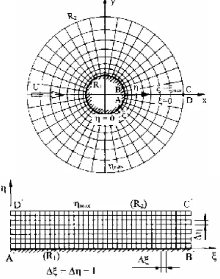
Figure 1 shows the physical and computational domains, where R1 and R2 are the dimensionless radii of the cylinder and that of the outer boundary, respectively. R2 represents the far field, where potential flow is assumed. Dirichlet-type boundary conditions (BCs) are used for the velocity components and Neumann-type BC for pressure on both R1 and R2.
Figure 1. The physical and computational domains
In order to satisfy the BCs accurately, boundary- fitted coordinates are used. The physical domain is mapped into a rectangular computational domain (see Fig. 1). Using appropriate mapping functions, the grid on the computational domain can be made equidistant, while providing a fine mesh on the physical domain near the cylinder and a coarse mesh in the far field. The independence studies where the appropriate radius ratio R2/R1, grid resolution and time step value are chosen are discussed in Dorogi and Baranyi [16]. Based on [16], in this study the
physical domain is characterized by R2/R1=160, the number of grid points are chosen to be 360×292 and the dimensionless time step is fixed at 0.0005.
The transformed governing equations and the BCs are solved using an in-house code based on finite difference method [17]. Fourth-order accurate difference schemes are applied for space derivatives, except for the convective terms which are discretised using a third-order modified upwind difference scheme [17]. The equations of motion and the two structural equations are integrated explicitly, the pressure Poisson equation is solved using successive over-relaxation (SOR) method and the continuity equation is satisfied in each time step.
The in-house code was extensively validated against available experimental and numerical results obtained for stationary cylinders [16, 17], forced cylinder motions [17] and free cylinder vibrations [16].
3. COMPUTATIONAL SETUP
As was mentioned earlier, there is a linear relationship between Re and U* for constant natural frequency
Re = 𝐾𝑈∗, (7)
where K=fNd2/ν is the non-dimensional natural frequency. Singh and Mittal [8] found different vortex structures by investigating the effect of Reynolds number at the constant reduced velocity of U*=4.92. In the range of Re=50–300 2S vortex- shedding mode (where two single vortices are shed from the cylinder in each motion period) was identified and P+S mode (a vortex pair and a single vortex are shed) was found over Re=300. In contrast, only 2S vortex structure was identified by Prasanth and Mittal [12] at K=16.6. The question arises if P+S mode can be observed by using larger K values.
If we know one point [say (𝑈0∗, Re0)] of the straight line represented by Eq. (7), the slope of the line can be determined, i.e., 𝐾 = Re0/𝑈0∗. In this study 𝑈0∗ is fixed at 𝑈0∗=4.92 (as in [8]) and Re0 is varied between Re0=171 and 220. Table 1 gives Re0, 𝑈0∗ and the corresponding approximate K values.
Table 1: The parameters of the computations Re0 𝑈0∗ 𝐾 = Re0/𝑈0∗ 171
4.92
34.7561
180 36.5854
185 37.6016
190 38.6179
200 40.6504
210 42.6829
215 43.6992
217 44.1057
250 50.813
From now on Re0 is used as a parameter to characterise the natural frequency only, in order to avoid rounding errors in K. Note that Re0 does not equal the Reynolds number Re. Re is varied in the range of Re=150–250, mass ratio is fixed at m*=10 and the structural damping coefficient is set to zero (ζ=0) in order to obtain large amplitude vibrations.
4. RESULTS AND DISCUSSION
In the literature the results obtained are usually plotted against either Re or U*. Singh and Mittal [8]
used U*St0 as an independent variable, where St0 is the dimensionless vortex shedding frequency for a stationary cylinder at Reynolds number Re taken from [18]. Physically, U*St0 is the ratio of the vortex shedding frequency for a stationary cylinder fv and the natural frequency of the oscillating body fN. Plotting the results against U*St0, the data sets belonging to different Re0 values are represented in the same range, which makes comparison easier.
In Figs. 2 and 3 the root-mean-square (rms) values of streamwise and transverse vibration components (x0rms and y0rms) are plotted against U*St0
for Re0=171 and 200. As expected, the cylinder response shows two-branch behaviour: an initial branch with small oscillation amplitudes and a lower branch with relatively large cylinder displacements.
It can be seen in Fig. 2 that for Re0=200 x0rms
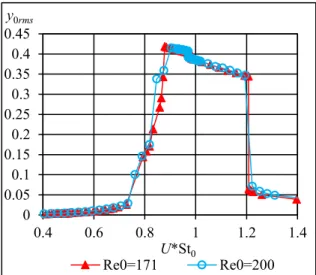
increases steeply up to x0rms≅0.023 over the approximate interval of U*St0≅0.92–0.98 then drops abruptly to a value of x0rms≅0.005. This phenomenon cannot be observed for Re0≅171, which suggests that only larger Re0 values result in a steep increase in the streamwise oscillation amplitude. A small jump can also be identified in y0rms (see Fig. 3) at around U*St0=0.98.
Figure 2. The rms values of streamwise cylinder displacement for Re0=171 and 200
Two different cylinder orbits are found in this study. In Fig. 4a distorted figure-eight motion can be seen, in which the streamwise oscillation frequency
is double that in the transverse direction (fx/fy=2). For raindrop-shaped motions, shown in Fig. 4b, the streamwise and transverse cylinder oscillation frequencies are identical (fx/fy=1).
Figure 3. The rms values of transverse cylinder displacement for Re0=171 and 200
-0.6 0 0.6
0 0.15
x [–]
-0.6 0 0.6
y [–]
0 0.15
x [–]
(a) (b)
Figure 4. Cylinder paths at Re=190 and 196 for Re0=200
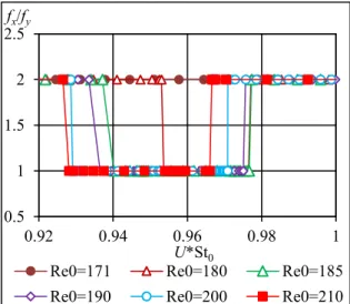
In order to investigate the effect of Re0 on the cylinder response, systematic computations are carried out. In Fig. 5 the frequency ratio fx/fy is shown against U*St0 for the investigated Re0 values. It can be seen that Re0=180 is the first natural frequency level where both raindrop-shaped and distorted figure-eight motions can occur. Varying Re0 between Re0=180 and 215, raindrop-shaped motion occurs over a narrow U*St0 domain that widens with increasing Re0. A distorted figure-eight cylinder path is found outside the range where fx/fy=1.
In Fig. 6 x0rms is plotted against U*St0 for different Re0 values ranging from Re0=171 to 215.
Values at around 0.007 are for the distorted figure- eight path, while higher values indicate raindrop- shaped motion (note that Re0=171 displays only figure-eight motion). Peak x0rms values increase with 0
0.005 0.01 0.015 0.02 0.025
0.4 0.6 0.8 1 1.2 1.4
x0rms
U*St0
Re0=171 Re0=200
0 0.05 0.1 0.15 0.2 0.25 0.3 0.35 0.4 0.45
0.4 0.6 0.8 1 1.2 1.4
y0rms
U*St0
Re0=171 Re0=200
increasing Re0. It can also be seen that abrupt jumps occur at the upper boundary separating the raindrop- shaped and figure-eight motion ranges. At the two sides of a jump the vortex structure shows substantial changes, as shown in Fig. 7. It can be seen that P+S vortex-shedding mode belongs to raindrop-shaped motions (Fig. 7a) and 2S mode is associated with figure-eight paths (Fig. 7b). In the figure blue colour refers to negative (rotating anti-clockwise) and red colour shows positive (clockwise) vortices. The location of the switch in the vortex structure shifts to lower U*St0 values for increasing Re0 values.
Figure 5. Streamwise to transverse oscillation frequency ratio vs. U*St0 for different Re0 values
Figure 6. The rms values of streamwise cylinder displacement vs. U*St0 for different Re0 values
Figures 8 and 9 show the rms values of lift and drag (CLrms and CDrms) against U*St0 for Re0=185, 200 and 215. The results show similar features for all of the investigated Re0 values (Re0=180–215) so only three curves are presented here to avoid confusion. Both CLrms and CDrms show jumps at the upper boundary separating raindrop-shaped and
distorted figure-eight motion domains, as can also be seen in x0rms (Fig. 6). It can also be observed that by increasing Re0, the CLrms curves shift upwards in the raindrop-shaped and downwards in the figure-eight motion domains (indicated by arrows in Fig. 8). In contrast, CDrms curves belonging to increasing Re0
values shift to higher values in both the raindrop- shaped and figure-eight motion domains (indicated by arrows in Fig. 9).
(a) Re=201.65
(b) Re=201.67
Figure 7. Vortex structures (red: positive, blue:
negative vorticity) for raindrop-shaped (a) and distorted figure-eight (b) motions for Re0=200
Figure 10 shows the time-mean values of lift coefficient CLmean against U*St0 for three different Re0 values. It can be seen that CLmean is negligible in the range where figure-eight motion is found, while the absolute value of CLmean increases with U*St0
where the cylinder follows a raindrop-shaped orbit.
In the raindrop-shaped motion domain two state curves exist and the solution jumps abruptly between them.
Figure 8. The rms of lift against U*St0 for Re0=185, 200 and 215
0.5 1 1.5 2 2.5
0.92 0.94 0.96 0.98 1
fx/fy
U*St0
Re0=171 Re0=180 Re0=185
Re0=190 Re0=200 Re0=210
0 0.01 0.02 0.03 0.04
0.92 0.94 0.96 0.98 1
x0rms
U*St0
Re0=171 Re0=180 Re0=185
Re0=190 Re0=200 Re0=210
Re0=215
0 0.05 0.1 0.15 0.2 0.25 0.3 0.35 0.4
0.92 0.94 0.96 0.98 1
CLrms
U*St0
Re0=185 Re0=200 Re0=215
Re0 Re0
Figure 9. The rms of drag against U*St0 for Re0=185, 200 and 215
Figure 10. Time-mean values of lift against U*St0
for Re0=185, 200 and 215
In Fig. 11 (CD,CL) limit cycle curves are shown before and after the jump. The curves appear to be mirror images of each other, which is due to a symmetry breaking bifurcation. In a non-linear system there are two attractors each with a basin of attraction [19]. If the set of parameters (e.g. Re, U*, m*, etc.) is close to the boundary separating the basins of attractor then a tiny change can lead to an abrupt jump (see Fig. 10). The paths of the cylinder are mirror images of each other for the pre- and post- jump cases shown in Fig. 12.
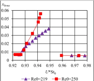
In Fig. 13 x0rms is shown for Re0=219 and 250. It can be seen that x0rms increases steeply when increasing U*St0 up to a critical value, similarly to values observed for Re0<215 (see Fig. 6). At the critical U*St0 value the flow becomes irregular, which is the reason that some of the computation points are missing in the figure. After the chaotic flow regime x0rms jumps to smaller values (see Fig.
13) and the cylinder path shifts back to distorted figure-eight.
-0.6 -0.4 -0.2 0 0.2 0.4 0.6
1.5 2 2.5 3
CD [-]
CL [-]
Figure 11. Limit cycle (CD, CL) in pre- and post- jump cases (thin curve: Re=206.8; thick curve:
Re=206.9) for Re0=215
-0.6 -0.4 -0.2 0 0.2 0.4 0.6
0 0.05 0.1 0.15 x0 [-]
y0 [-]
Figure 12. The path of the cylinder before and after the jump (thin curve: Re=206.8; thick curve:
Re=206.9) for Re0=215
Figure 13. The rms of streamwise cylinder displacement for Re0=219 and 250
In Fig. 14 the time history of the streamwise cylinder displacement is shown for a typical chaotic 0.350.37
0.39 0.41 0.43 0.45 0.47 0.49 0.51 0.53 0.55
0.92 0.94 0.96 0.98 1
CDrms
U*St0
Re0=185 Re0=200 Re0=215
Re0
Re0
-0.2 -0.15 -0.1 -0.05 0 0.05 0.1 0.15 0.2
0.92 0.94 0.96 0.98 1
CLmean
U*St0
Re0=185 Re0=200 Re0=215
0 0.01 0.02 0.03 0.04 0.05 0.06
0.92 0.93 0.94 0.95 0.96 0.97 0.98 x0rms
U*St0
Re0=219 Re0=250
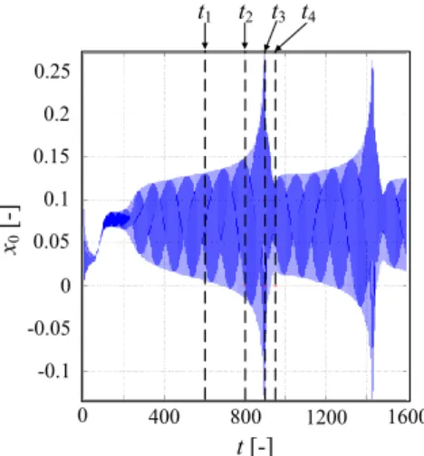
flow. It can be seen that in the dimensionless time interval t=t1–t2 (indicated in the figure) raindrop- shaped motion develops; this conclusion is supported by the P+S vortex shedding mode shown in Fig. 15a at t=t2. It can also be observed that the signal at t=t1– t2 is not quasi-periodic, because its amplitude varies with time. The vortex structures change significantly between t=t3 and t4 (indicated in Fig. 14). At t=t3 2S mode (see Fig. 15b) and at t=t4 P+S vortex-shedding modes (Fig. 15c) are found.
0 400 800 1200 1600
0
-0.1 0.1 0.2 0.25
0.15
0.05
-0.05 x0 [-]
t [-]
t1 t2 t3 t4
Figure 14. Time history of streamwise cylinder displacement at Re0=215.5 for Re0=219
(a) t=t2=800
(b) t=t3=900
(c) t=t4=950
Figure 15. Vortex structures (red: positive, blue:
negative vorticity) at different time instants for Re=215.5 and Re0=219
5. CONCLUSIONS
In this study fluid flow around a freely vibrating circular cylinder in two-degrees-of freedom is investigated at low Reynolds numbers using two- dimensional numerical simulations. Cylinder response and aerodynamic force coefficients are
investigated at different non-dimensional natural frequency values K. Assuming that 𝑈∗= 𝑈0∗= 4.92 at Re=Re0=171–250, non-dimensional natural frequency can be obtained as 𝐾 = Re0/𝑈0∗. In this paper U*St0 is used as an independent variable. The main findings of the study are as follows:
Distorted figure-eight motion is identified where the root-mean-square (rms) of streamwise cylinder displacement is in the range of x0rms≅O(10-3). In case of raindrop-shaped cylinder motion x0rms approaches higher values (x0rms≅O(10-2)).
For Re0<180 only distorted figure-eight cylinder paths are found. Both distorted figure-eight and raindrop-shaped paths are identified between Re0=180 and 215. The width of the domain where raindrop-shaped motion is identified tends to increase with Re0.
The rms values of lift CLrms shift upwards in the raindrop-shaped motion regime and downwards in the distorted figure-eight regime by increasing Re0 when plotted against U*St0. The rms values of drag CDrms shift to higher values with increasing Re0 in both domains.
Abrupt jumps are found in x0rms, CLrms and CDrms. at the upper boundary separating raindrop- shaped and distorted figure-eight motion domains. In this location the vortex structure switches from P+S mode (a vortex pair and a single vortex are shed from the cylinder) to 2S mode (two single vortices).
The time mean value of lift CLmean is negligibly small in the distorted figure-eight domain and shows a significant increase in the raindrop- shaped motion domain.
CLmean jumps abruptly between two solutions.
Plotting limit cycle curves (CD, CL) in the pre- and post-jump cases shows that these curves are mirror images of each other.
Irregular cylinder motion is observed for Re0>215 at the upper boundary that separates the two domains.
ACKNOWLEDGEMENTS
The research was supported by the EFOP-3.6.1-16- 00011 “Younger and Renewing University – Innovative Knowledge City – institutional development of the University of Miskolc aiming at intelligent specialization” project implemented in the framework of the Széchenyi 2020 program. The realization of this project is supported by the European Union, co-financed by the European Social Fund.
REFERENCES
[1] Khalak, A., and Williamson, C.H.K., 1999,
“Motions, forces and mode transitions in vortex-induced vibrations at low mass- damping”, J Fluid Struct, Vol. 13, pp. 813–851.
[2] Feng, CC., 1968, “The measurement of vortex- induced effects in flow past stationary and oscillating circular and D-section cylinders”, Master thesis, University of British Columbia, Vancouver, B.C., Canada
[3] Jauvtis, N., and Williamson, C.H.K., 2004,
“The effect of two degrees of freedom on vortex-induced vibration at low mass and damping”, J Fluid Mech, Vol. 509, pp. 23–62.
[4] Sarpkaya, T., 1995, “Hydrodynamic damping, flow-induced oscillations, and biharmonic response”, J Offshore Mech Arct, Vol. 117, pp.
232–238.
[5] Sanchis, A., 2009, “Two degrees of freedom vortex-induced vibrations of a rigid circular cylinder with varying natural frequencies in the x and y directions”, Proc. ASME 2009 28th International Conference on Ocean, Offshore and Arctic Engineering, Honolulu, Hawaii, USA, pp. 889–894.
[6] Govardhan, R.N., and Williamson, C.H.K., 2006, “Defining the ‘modified Griffin plot’ in vortex-induced vibration: revealing the effect of Reynolds number using controlled damping”, J Fluid Mech, Vol. 561, pp. 147–
180.
[7] Klamo, J.T., Leonard, A., and Roshko, A., 2006, “The effect of damping on the amplitude and frequency response of a freely vibrating cylinder in cross-flow”, J Fluid Struct, Vol. 22, pp. 845–856.
[8] Singh, S.P., and Mittal, S., 2005, “Vortex- induced oscillations at low Reynolds numbers:
hysteresis and vortex-shedding modes”, J Fluid Struct, Vol. 20, pp. 1085–1104.
[9] Leontini, J.S., Thompson, M.C., and Hourigan, K., 2006, “The beginning of branching behavior of vortex-induced vibration during two-dimensional flow”, J Fluid Struct, Vol. 22, pp. 857–864.
[10] Willden, R.H.J., and Graham, J.M.R., 2006,
“Three distinct response regimes for transverse vortex-induced vibrations of circular cylinders at low Reynolds numbers”, J Fluid Struct, Vol.
22, pp. 885–895.
[11] Bahmani, M.H., and Akbari, M.H., 2010,
“Effect of mass and damping ratios on VIV of a circular cylinder”, Ocean Eng, Vol. 37, pp.
511–519.
[12] Prasanth, T.K., and Mittal, S., 2008, “Vortex- induced vibrations of a circular cylinder at low Reynolds numbers”, J Fluid Mech, Vol. 594, pp. 463–491.
[13] Mittal, S., and Singh, S., 2005, “Vortex- induced vibrations at subcritical Re”, J Fluid Mech, Vol. 534, pp. 185–194.
[14] Mittal, S., and Kumar, V., 1999, “Finite element study of vortex-induced cross-flow and in-line oscillations of a circular cylinder at low Reynolds numbers”, Int J Numer Meth Fl, Vol.
31, pp. 1087–1120.
[15] Kang, Z., Ni, W., and Sun, L., 2016, “An experimental investigation of two-degree-of- freedom VIV trajectories of a cylinder at different scales of natural frequency ratios”, Ocean Eng, Vol. 126, pp. 187–202.
[16] Dorogi, D., Baranyi, L., 2018, “Numerical simulation of a freely vibrating circular cylinder with different natural frequencies”, Ocean Eng, Vol. 158, pp. 196–207.
[17] Baranyi, L., 2008, “Numerical simulation of flow around an orbiting cylinder at different ellipticity values”, J Fluid Struct, Vol. 24, pp.
883–906.
[18] Posdziech, P., and Grundmann, R., 2007, “A systematic approach to the numerical calculation of fundamental quantities of the two-dimensional flow over a circular cylinder”, J Fluid Struct, Vol. 23, pp. 479–499.
[19] Strogatz, S.H., 1994, Nonlinear Dynamics and Chaos, Westview Press