Three-dimensional carrier-envelope-phase map of focused few-cycle pulsed Gaussian beams
Miguel A. Porras
Grupo de Sistemas Complejos, ETSIME, Universidad Politécnica de Madrid, Rios Rosas 21, Madrid 28003, Spain Zoltán L. Horváth
Department of Optics and Quantum Electronics, University of Szeged, Dóm tér 9., Szeged 6720, Hungary Balázs Major*
ELI-ALPS, ELI-HU Non-Profit Ltd., Dugonics ter 13, Szeged 6720, Hungary
and Department of Optics and Quantum Electronics, University of Szeged, Dóm tér 9., Szeged 6720, Hungary
(Received 25 September 2018; published 12 December 2018)
We derive an analytical expression that describes the complete three-dimensional carrier-envelope-phase (CEP) distribution in the focal volume of ultrashort pulsed Gaussian beams focused by spherical mirrors or lenses. The focal CEP map depends on the so-called factor g specifying the frequency dependence of the beam width of the source few-cycle pulse, on its chirp, and on the small chromatic aberration introduced by a lens without appreciably distorting or broadening the few-cycle pulse. We show how to tailor the CEP map of mirror-focused and lens-focused few-cycle pulses in order to produce negligible transversal and axial CEP variations in specific regions of the focal volume for phase-sensitive interactions of light with matter taking place in a volume or on a surface. We propose a quasiachromatic doublet lens that can implement in practice these tailored CEP distributions.
DOI:10.1103/PhysRevA.98.063819
I. INTRODUCTION
In this paper we determine the three-dimensional (3D) carrier-envelope-phase (CEP) map or spatial variation of the CEP of broadband few-cycle pulses focused by mirrors or lenses and describe several mechanisms to tailor it for spe- cific applications. The CEP map is relevant to all nonlinear light-matter interaction experiments as high-harmonic or at- tosecond pulse generation, photoelectron emission from metal surfaces, nano-objects or structures, and in the control of chemical reactions in femtochemistry where the CEP is a crucial parameter determining the outcome of the experiment [1–5]. In gas high-order harmonic generation, for example, the extreme-ultraviolet (XUV) emission may even originate from a large portion of the focal volume, influencing its spectral content through phase matching [4,6–10]. The significance of the spatial distribution of few-cycle laser beam parameters in phase-matching properties of high-order harmonic generation has also been highlighted in Ref. [11]. Thus knowing and controlling the focal CEP variation along with a consequent choice of the material sample position and extent can be con- sidered as relevant as controlling the CEP of the laser source.
It has happened slowly and with difficulty to stop identi- fying the variation of the CEP through a focus with Gouy’s phase shift, probably because the former has its origin in the latter [12,13]. Gouy’s phase shift is an additional−π phase shift of a monochromatic constituent through the focus that changes its phase velocity, whereas the CEP shift is the shift
*Corresponding author: balazs.major@eli-alps.hu
of the phase of the carrier oscillations at the time of pulse peak due to the different and space-dependent phase and group velocities [14]. The precise on-axis and off-axis CEP map of ideally focused few-cycle transform-limited pulsed Gaussian beams was described in Ref. [15]. The deviation from Gouy’s phase shift is governed by the so-called factorgof the input beam also called the Porras factor in Ref. [16], which is deter- mined by the variation of the beam width with frequency [15].
On the experimental side, earlier measurements did not report conclusive deviations of the CEP shift from the Gouy’s phase shift [12,17,18]. Recent measurements based on spectral in- terferometry reported however strong deviations from Gouy’s phase shift and their relation with the wavelength-dependent properties of the input beam [19]. Very recently, direct mea- surement of the on-axis and off-axis CEP map based on the CEP sensitivity of the backscattered photoelectrons from a nanotip scanning the focal volume [16] confirmed the strong deviations from Gouy’s phase shift and corroborated the pre- dictions in Ref. [15], in particular, the predicted dependence with the g factor. These observations underscore the need to properly characterize the laser source in use—especially measuring its factorg—to get advanced control on the CEP and hence on the allied CEP-sensitive light-matter interac- tions [16]. Unfortunately, there are no studies on how the factorgdetermining the CEP map relates to the femtosecond laser source characteristics so that no effective control can be exercised on the CEP under close-to-ideal focusing conditions as with spherical or parabolic mirrors.
Soon after the demonstration of CEP sensitivity of dif- ferent physical processes, methods have been proposed to attain some control on axial variations of the CEP based
on dispersive material for specific applications [20,21]. We have previously studied the focusing of few-cycle pulses with lenses [22–24] and determined the precise conditions for lenses to focus to transform-limited few-cycle pulses traveling undistorted in the focal volume. We have also described how the on-axis CEP variation differs from that using mirrors as an effect of the small chromatic aberration introduced by the lens [22]. Although mirrors are thought to be generally preferable, chromatic focusing has recently been proposed as an additional control knob for high-order harmonic genera- tion [25]. Also, we have previously found that a small pulse chirp, lengthening the pulse by, e.g., less that one femtosec- ond, strongly affects the on-axis CEP variation [23]. Chirped femtosecond pulses have also been used to control high-order harmonic generation [26–30], chemical reactions [31], and terahertz generation [32]. Chromatic aberration and chirp thus offer two control parameters, often used in femtosecond light- matter interaction experiments, to control the CEP map.
However, the capability of chromatic focusing and chirp to modify and control the CEP map has only been analyzed along the optical axis and not off axis, whereas nonlinear interactions generally take place in a volume not just on axis [1,4,33,34]. It is thus of interest to these experiments to investigate how the complete 3D CEP map depends on g, chromatic aberration, and chirp so that specific axial and transversal CEP variations (e.g., no axial and/or radial CEP variation) required for particular CEP-sensitive interactions at specific target positions and extents can be tailored acting on these parameters.
Thus, in Sec. II we evaluate the complete 3D CEP map, recalling the conditions under which the few-cycle pulses can be focused without appreciable distortion. In Sec.IIIwe analyze the conditions under which the CEP map can be made flat, axially, transversally, or both, in specific locations in the focal volumewith a focusing mirror or with a lens using small chirps and chromatic aberrations. In Sec. IVwe exemplify the results by showing these small pulse chirps and the tunable small chromatic aberrations are easily provided by a separable achromatic doublet that would allow for generating these tailored CEP maps in practice.
II. THE THREE-DIMENSIONAL CEP MAP
If the beam to be focused is of sufficiently high quality—
the beam-quality factor M2 [35], is close to unity—, its spectrum can be assumed to be of the form of the collimated Gaussian beam ˆEin(ω, r)=pˆin(ω) exp(−r2/sL2), where r is the radial coordinate from the optical axis and ˆpin(ω) is the on-axis spectrum of bandwidth ω about the laser car- rier frequency ω0. The beam spot size sL and the asso- ciated Rayleigh distance L=ωsL2/2c depend, in general, on frequency ω. Since applications require careful focusing to a nearly diffraction-limited beam, we can assume that the spectrum after the focusing system is given from well- known Gaussian beam formulas in the Debye approxima- tion (Lf or no appreciable focal shift) by ˆE(ω, r, z)=
ˆ
p(ω)(−f/q) exp(iωr2/2cq) exp(iωz/c), wherezis the axial distance from the exit plane of the focusing system, q= Z−iLR andLR =f2/L are the complex beam parameter and Rayleigh distance of the focused beam, f is the focal
length, which may depend on frequency, Z=z−f is an axial coordinate with its origin at the focal point at each frequency, and ˆp(ω) may differ from ˆpin(ω) in the possible spectral changes introduced by the focusing system. The space-dependent parts of the spectral amplitude and phase at each point after the focusing system are then given by
a(ω, r, z)= f LR
1
[1+(Z/LR)2]1/2exp[−r2/s2(Z)], (1) ϕ(ω, r, z)= −π
2 −tan−1 Z
LR
+ ωr2 2cR(Z)+ω
cz, (2) wheres2(Z)=sf2[1+(Z/LR)2]1/2, sf2 =2cLR/ω,R(Z)= Z[1+(LR/Z)2].
It has been shown [22] that the above Gaussian-beam formulas describe accurately the spectrum of the focused pulsed beam ifsL is small enough compared to the mirror or lens radius for aperture effects and spherical aberration to be negligible. Under this condition, and if the focusing system is a lens, pulse broadening introduced by the lens material dispersion is substantially the same as that introduced by a slab of the lens material and thickness equal to the lens central thickness D, i.e., ˆp(ω)=pˆin(ω) exp[iDn(ω)], where n(ω) is the lens material refractive index [22]. It is then possible to have a transform-limited few-cycle pulse after the lens by simply precompensating for the dispersion introduced by that plate as usually performed with standard pulse-shaping techniques (e.g., group-velocity dispersion and/or third-order dispersion compensation, depending on the pulse duration and lens thicknessD). We may also have a pulse with positive or negative chirp after the lens by under- or overcompensating that material dispersion. It has also been shown [22] that the distortions in the pulse shape about the focus originating from the lens chromatic aberration, measured by the parameter γ =ω(df/dω)/LR (evaluated at the carrier frequency), are negligible if |γ| ω0/ω, a condition that is easily given with real lenses. Under these conditions, the only source of distortion in the pulse shape is the intrinsic distortion due to the transverse limitation of a focused beam, i.e., to diffrac- tion, distortions that are generally very small, and have been shown to be accurately described by the first-order theory of diffraction effects in few-cycle pulses [36]. In this theory, the time-domain electric field, or inverse Fourier transform of E(ω, r, z), is expressed as the enveloped carrier oscillationsˆ E(t, r, z)=A(t, r, z) exp{−i[ω0t−ϕ(ω0, r, z)]}with an en- velope given by
A(t, r, z)a(ω0, r, z)p(τ)+ia(ω0, r, z)dp(τ) dτ . (3) The prime signs stand for a derivative with respect to fre- quency,p(τ) is the inverse Fourier transform of ˆp(ω) eval- uated at the local timeτ =t−ϕ(ω0, r, z). The second term on the right-hand side of Eq. (3) accounts for the small diffraction-induced changes in the pulse shape about the focus.
The CEP at a point (r, z) is the phase of the carrier oscillations at the time of the pulse peak, i.e., (r, z)= −ω0[τ(r, z)+ϕ(ω0, r, z)]+ϕ(ω0, r, z)+φ(r, z), whereτ(r, z) is the time at which|A(τ, r, z)|peaks andφ(r, z) is the argument ofA(τ, r, z) at that time. Thus, if we take the
focal point at the carrier frequency (r=0, z=f(ω0)≡f0) (focal point for short) as a reference point, the CEP shift from the focal point is given by (r, z)=(r, z)−(0, f0), which can be separated in the two contributions,
1(r, z)=[−ω0ϕ(ω0, r, z)+ϕ(ω0, r, z)]
−[−ω0ϕ(ω0,0, f0)+ϕ(ω0,0, f0)], (4) and
2(r, z)= −ω0[τ(r, z)−τ(0, f0)]+φ(r, z)−φ(0, f0)
≡ −ω0τ(r, z)+φ(r, z). (5) The first contribution is independent of the shape p(τ) of the pulse, the only one considered in Ref. [15] for focusing without chromatic aberration, and has been verified exper- imentally to describe the actual CEP map with transform- limited (unchirped Gaussian) pulses [16] (which implies that the second contribution is negligible with transform-limited pulses). The effect of chromatic aberration on the CEP was considered in Ref. [22] but limited to on-axis points (r=0).
The second contribution includes the effect of the small pulse reshaping and depends on the pulse shape itself. For on-axis points only, it has been shown that any small amount of chirp in the focused pulse drastically alters the CEP map [23].
Here we evaluate the two contributions for off-axis points with chirped or unchirped Gaussian pulses, providing thus a complete description of the CEP map about the focus.
Evaluation of Eq. (4) is a straightforward but lengthy (and tedious) exercise of algebra and calculation of derivatives of which we summarize the most relevant points. With the normalized variablesζ =Z/LR andρ =r/s(Z) the spectral phase reads asϕ = −π/2−tan−1(ζ)+ρ2ζ +(ω/c)z. Both ζ and ρ depend on ω because f, L, and hence LR, Z= z−f, and all other quantities in the Gaussian-beam formulas where they appear, depend onω. Careful evaluation of their derivatives yield ζ= −(f/LR)−ζ(LR/LR) and (ρ2)= ρ2[1/ω−(LR/LR)−2ζ ζ/(1+ζ2)]. After long algebra, the first contribution to the CEP shift from the focal point is obtained to be
1(r, z)= −tan−1 Z
LR
+ 1−2s2r(Z)2
1+
Z LR
2
×
g Z
LR
+γ
Z LR
2
+γ r2
s2(Z), (6) where
g= −LR
LRω, γ = f
LRω, (7)
and where all frequency-dependent quantities are evaluated at the carrier frequency ω0, e.g., Z=z−f0 is the axial distance from the focal point. Although parameterg is ex- pressed in Eq. (7) using the Rayleigh lengthLRof the focused beam, it depends solely on input beam parameters and can be calculated using the Rayleigh lengthL or waist size sL of the input beam asg=Lω/L≈1+2sLω/sL[15,22,24].
The dependence ofgon the parameters of the laser source is yet unclear and should be the subject of future experimental studies. The results of Hoff and co-workers suggest [16], e.g.,
that it depends on day-to-day tuning and alignment of the laser source. Some easily interpretable values ofgare described in Refs. [15,24].
Similarly, the spectral amplitude, expressed in the dimen- sionless variables, is given by a=(f/LR) exp(−ρ2)/(1+ ζ2)1/2. After some algebra, its derivative with respect to frequency can be written asa=h(ρ, ζ)a, where
h(ρ, ζ)=h(ζ)−ρ2 1
ω −LR
LR − 2ζ ζ 1+ζ2
, (8)
h(ζ)= f f
1+ f
LR
ζ 1+ζ2
−LR LR
1− ζ2 1+ζ2
, (9) and where all frequency-dependent quantities are evaluated at the carrier frequency. The complex envelope in Eq. (3) then yields A[p(τ)+ih(ρ, ζ)dp/dτ]a, which, being a first- order approximation (second-order derivatives are neglected), is conveniently replaced with Ap[τ +ih(ρ, ζ)]a, having the same first-order approximation. Assuming that the on-axis pulse immediately after the lens is the Gaussian pulsep(τ)= (T /b) exp(−τ2/b2), whereb2=T2−2iC, Cis a resid- ual chirp, and T is the transform-limited duration {actual durationTC =T[1+(2C/T2)2]1/2}, the reshaped real amplitude’s temporal shape in the focal region is found to be
|A| T b exp
h2(ρ, ζ)
T2 exp
−
τ −2C
T2
h(ρ, ζ)2
TC2
. (10) Thus, reshaping due to the strong localization in the focal region consists of a drift of the time of pulse peak from point to point of space given byτ(ρ, ζ)=(2C/T2)h(ρ, ζ).
This expression allows to evaluate−ω0[τ(r, z)−τ(0, f0)]=
−ω0(2C/T2)[h(ρ, ζ)−h(0,0)] in Eq. (5) for the second contribution to the CEP shift from the focal point. Similar calculations allow for concluding that the difference in the phases of the envelopes at the time of the drifted peaks φ(r, z)−φ(0, f0) does not give a significant contribution to the CEP shift. After some algebra, Eq. (5) for the second contribution to the CEP shift then yields
2(r, z)= 2C T2
1−2s2r(Z2)
1+
Z LR
2
−γ Z
LR
+g Z
LR 2
+ 2C
T2(1+g) r2
s2(Z), (11)
where again all quantities are evaluated at the carrier fre- quency. The total CEP shift from the focal point is finally obtained to be
(r, z)= −tan−1 Z
LR
+ 1−2s2r(Z)2
1+
Z LR
2
×
G Z
LR
+ Z
LR 2
+
+ 2C
T2 r2
s2(Z), (12)
where
G≡g−γ 2C
T2, ≡γ +g 2C
T2. (13)
These equations provide the complete 3D CEP map for the focusing conditions of interest in many applications to a nearly diffraction-limited and transform-limited pulsed beam.
The most relevant novelty compared to the on-axis formula is the term in the third row that makes the CEP on the focal plane to present, in general, a quadratic variation with radial distance. Out of the focal plane, the CEP has also a positive or negative quadratic variation, depending on the specific value ofZ. Along caustic surfacesr/s(z)=const, the CEP variation is more pronounced or less pronounced than Gouy’s phase, depending on the value ofgof the input beam and the specific caustic surface and as described elsewhere [15,16,23].
The CEP shift along the caustic surfacer/s(Z)=1/√ 2 al- ways equals Gouy’s phase shift. For further development, we rewrite (12) more compactly as
= −tan−1ζ +ζ G+ζ2
1+ζ2 (1−2ρ2)+Pρ2, (14) where
P =+2C/T2=γ+(g+1) 2C
T2. (15)
The validity of our analytical approach has been confirmed experimentally by Hoff and co-workers [16] for unchirped pulses focused by mirrors, even if the beam was not perfectly Gaussian (M2 =1.2). We note, however, that intense few- cycle pulsed laser beams are often obtained experimentally by using hollow-core fiber compression techniques produc- ing beams having profiles described by truncated Bessel modes [11,37–39]. If the mode is truncated at first zero of the Bessel function, our expressions derived for Gaussian beams are expected to give a fair approximation for the CEP of the clipped Bessel beam. Studying beams with Bessel or truncated Bessel profiles are outside the scope of this paper.
III. TAILORING THE THREE-DIMENSIONAL CEP MAP The CEP map can be used and manipulated in a number of ways, depending on the particular application. For example, it is generally desirable to have a constant CEP in the volume of the target to avoid CEP-integration effects that may wash out the sensitivity to the CEP of the light-matter interaction. One may then evaluate the CEP standard deviation in the target volume and minimize it. In the following we assume a laser source of certain factor g (that cannot easily be modified), a target at position Z of narrow axial thickness compared to LR, and a large transversal size compared to s(Z). We can also consider a light-matter interaction that depends on a certain powernof the intensityIn∝exp[−2nr2/s2(Z)]= exp(−2nρ2). This is an alternative way to consider a transver- sally limited target of effective radiuss(Z)/√
nsmaller than the beam radius, e.g., negligible transversal size forn→ ∞.
The effective CEP in the thin sample or average CEP withIn is found to be
= −tan−1ζ+ζ G+ζ2 1+ζ2
1−1
n
+ P
2n, (16)
with a transversal standard deviation given by (− )21/2 = 1
n
Gζ +ζ2 1+ζ2 −P
2
. (17) For a given sample position ζ, we may wish to have no transversal variation of the CEP, no local axial variation of the CEP, or both, acting on the two control parameters at hand, namely, pulse chirp and lens chromatic aberration. No transversal variation requires
2ζ G+2ζ2−(1+ζ2)P =0, (18) locally vanishing axial variation of the effective CEP at posi- tionζ and, in particular, vanishing on-axis CEP variation for n→ ∞requires
−(1+ζ2)+(1−ζ2)G
1−1 n
+2ζ
1−1
n
=0, (19) as obtained by equating to zero the derivative of Eq. (16) with respect toζ.
A. Design of the CEP map with focusing mirrors Since, in most experiments, mirrors are used to focus few- cycle pulses, we first analyze if the above conditions can be given with a mirror in which caseγ =0. ThenG=g, = g(2C/T2), andP =(1+g)(2C/T2). From Eq. (19), no axial CEP variation at the focusζ =0 occurs, irrespective of the chirp, only with the specific value ofg=1/(1−1/n) of the input pulse, org=1 for the on-axis CEP, and therefore it is not generally possible. From Eq. (18), the CEP across the focal plane is constant only ifP =(g+1)(2C/T2)= 0, i.e., requires a transform-limited pulse. Any chirp induces a CEP variation across the focal plane. Axially and radially constant CEPs occur only given with input laser pulses with g=1 andC=0.
In many experiments the target (e.g., a gas nozzle) is placed slightly out of focus, preferably in its second half.
Equation (18) for a transversally flat CEP at 0<|ζ|<1 in the case of a mirror yields the needed relative pulse chirp,
2C
T2 = 2ζ g
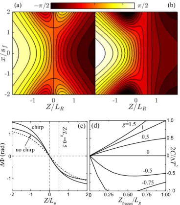
g(1−ζ2)+(1+ζ2). (20) Figures 1(a) and 1(b) are examples of CEP maps in the focal volume of input focused pulses withg= −0.5, having radially flat CEPs at ζ =0 with transform-limited pulses (C=0) and radially flat CEPs in the middle of the second half of the focal region with slightly chirped pulses (2C/T2=
−0.571). Figure 1(c)shows the corresponding on-axis axial variations, and Fig.1(d)shows the relative chirp 2C/T2to have transversally flat CEPs at different positionsζfrozenin the second half of the focal region for a few (supposedly) typical values of the factorg of the input beam. The relative chirp providing a radially flat CEP in the first half of the focal region has an opposite sign. As seen, chirping the pulse could be useful in practice (does not entail important pulse broadening) to have transversally flat CEPs at a desired axial position in the focal region for input pulses withg >−1.
(a) (b)
FIG. 1. For spherical mirror focusing, focal CEP maps (cut along they=0 plane) for an input beam withg= −0.5, (a) transform- limited pulse 2C/T2=0, and (b) chirped pulse 2C/T2=
−0.571. The CEP is transversally flat on the focal plane in (a) and atZ=LR/2 in (b). (c) Axial variation of the CEP in the two above cases (solid curves) compared to Gouy’s phase shift (dashed curve).
(d) Needed relative chirp as a function of the position Zfrozen at which the CEP is constant transversally for a few values ofgof the input pulse. Chirps with opposite signs cause the same constant CEP transversally in the first half of the focal region.
We instead may wish to have a CEP with no axial variation at a certain position 0<|ζ|<1 in the focal volume. Condi- tion (19) yields the chirp,
2C
T2 =1+ζ2−(1−ζ2)g 1−1n 2ζ g
1−1n . (21)
Unfortunately, the chirp values are considerably large for most values ofg. Only forg >1, a reasonably small chirp produces a locally constant CEP within the focal region as shown in Fig.2(a)for the effective CEP withn=4 and in the second half of the focal region with positive chirps (opposite chirps produce the same effect in the first half). With the choice ofn=4 the examples shown are representative for the case of high-order harmonic generation since the intensity of the generated XUV radiation scales approximately with the fourth power of the laser field intensity [40]. We also note that the curves do not change qualitatively for different values ofn.
Of particular interest is the situation in which the CEP is constant transversally and axially. Equating (20) and (21), this effect is seen to be possible in the focal region only with an input beam withg1.15 at a certain position ζ in [−1,1]
[where the curves in Figs.1(d)and2(a)intersect] that depends on the particular value of g. This relevant position in the
(d)
FIG. 2. (a) Needed relative chirp as a function of the position Zfrozen at which the effective CEP with n=4 is locally constant axially for a few values of g of the input beam for which this chirp is relatively low. Chirps with opposite signs cause the same locally constant axial CEP variation in the first half of the fo- cal region. (b) Needed relative chirp to freeze the effective CEP with n=4 both axially and transversally and the position within the focus at which this happens as functions of the values of g for which this effect is possible. (c) On-axis and effective CEPs withn=4 (solid curves) forg=1.26 and 2C/T2=0.574 and Gouy’s phase (dashed curve), showing locally constant effective CEPs atZ=LR/2. (d) CEP map in the focal region forg=1.26 and 2C/T2=0.574, showing also a transversally constant CEP atZ=LR/2.
second half of the focus and the required chirp are depicted in Fig.2(b)as functions ofg. Note that since opposite chirps produce the same CEP freezing effect in the first half of the focal region as in the second half, only results forζ in [0,1]
are depicted. The curves end atg=1/(1−1/n) at the focus with no chirp. For example, with an input pulse withg=1.26, the chirp 2C/T2=0.574 leads to the axially frozen effec- tive CEP with n=4 at ζ =0.5 as seen in Fig. 2(c). The transversally and axially flat CEP map atζ =0.5 is seen in Fig.2(d).
These results underscore the need to characterize the fem- tosecond laser source in use by measuring its factor g. By doing this we not only will know the possible CEP maps about the focus of the mirror, but also will know if the CEP map can be adapted to particular applications using small amounts of chirp as a control knob or suitably positioning the sample according to the CEP maps.
B. Design of the CEP map with lenses
The use of a lens offers more possibilities. According to Eq. (19), we can have a CEP map with no axial variation at the focus with input pulses of any value ofgif the chromatic
FIG. 3. (a) Chromatic aberration parameter γ as a function of the relative chirp 2C/T2 (a) to freeze axially the on-axis CEP at the focal point for different values of g of the input pulse. (b) The same but to have a transversally flat CEP on the focal plane.
(c) and (d) Chromatic aberration and chirp to produce on-axis and transversally frozen CEPs at the focus. Positive chromatic aberration requires negative chirp (solid curves) and vice versa (dashed curves).
aberrationγand the relative chirp 2C/T2verify γ 2C
T2 =g−m, (22)
wherem=(1−1/n)−1. Figure3(a)shows theγ −2C/T2 curves determined by Eq. (22), limited to relative chirps
|2C/T2|<1 so as not to enlarge excessively the pulse for different values of its g parameter in the particular case of n→ ∞(m=1), i.e., to freeze the on-axis CEP variation at the focus. For other values of nthe curves are qualitatively similar. As an example, the particular CEP map for an input pulse withg=0 having an on-axis maximum atζ =0 using the relative chirp 2C/T2=0.5 and the chromatic aberration γ = −2 is plotted in Fig. 4(a). With chirp and chromatic aberration of opposite signs, the CEP map would feature a minimum.
Instead, we may wish to have the same CEP at all points of the focal plane. According to Eq. (18), a transversally constant CEP imposes the linear relation,
γ = −(g+1) 2C
T2. (23)
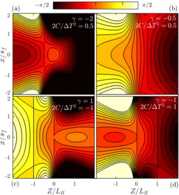
Theγ −2C/T2 lines determined by Eq. (23) are depicted in Fig. 3(b) for the same values of the g parameter as in Fig. 3(a). The particular CEP map with a flat CEP on the focal plane for an input pulse with g=0 using relative chirp 2C/T2=0.5 and γ = −0.5 is plotted in Fig. 4(b) for illustration purposes. Chirp and chromatic aberration of opposite signs would also produce a flat CEP on the focal plane.
FIG. 4. CEP maps in the focal volume (y=0 sections) forg=0 and the indicated values ofγ and 2C/T2. The CEP atζ =0 is axially constant in (a), transversally constant in (b), and axially and transversally constant in (c) and (d) with a maximum in (c) and a minimum in (d).
Although axially and transversally flat CEPs at the focus with a focusing mirror require a transform-limited input pulse with a particular value of g with a lens, this particularly relevant CEP map is possible with a variety of values ofg.
From Eqs. (22) and (23) we obtain the needed chirp and chromatic aberration as
2C T2 = ±
m−g
1+g, γ = ∓
(1+g)(m−g). (24) These values are the points of intersection of the curves in Figs. 3(a)and3(b)for each specific value of g, intersection points that exist for input pulses with−1gm, and are represented in Figs. 3(c) and 3(d) as functions of g in the particular case of n→ ∞ (m=1). Positive and negative chromatic aberrations correspond to negative and positive chirps in Eq. (24) or solid and dashed curves in Figs. 3(c) and3(d). Thus, given the factor g of the input pulse, there are two specific values of chromatic aberration and chirp to tailor an axially and transversally flat CEP map at the focus.
Only for 0g1 [black curves in Figs. 3(a) and 3(b)], however, the chirp can be considered small enough according to our criterion of|2C/T2|<1. As a couple of examples, the CEP maps corresponding to input pulses characterized by g=0 with γ = +1, 2C/T2= −1 (with a local ax- ial maximum at ζ =0) and with γ = −1,2C/T2 = +1 (with a local minimum) are plotted in Figs.4(c)and4(d).
Also, it is generally possible to freeze the CEP at particular locations out of focus. The required chromatic aberrations
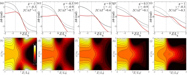
FIG. 5. Upper plots: On-axis (n→ ∞) CEP shift for input pulses with the indicated values ofg, focused by a lens with the indicated values of chromatic aberrationγ and chirp 2C/T2 such that the CEP is approximately flat in the first half of the focus (red curves). The dashed curves represent Gouy’s phase shift for reference, and the black curves represent the CEP shift in the case of focusing without chromatic aberration and without chirp. Lower plots: Corresponding CEP maps (y=0 sections) showing that the CEP is also transversally flat at positions about−LR/2 as indicated by the vertical dashed lines in the upper plots.
can be straightforwardly obtained from Eqs. (18) and (19), but the obtained expressions forγ and 2C/T2are long and cumbersome. In Ref. [23], it has been shown that, irrespective of the value ofg, a small chromatic aberrationγin [−1,0] or in [0,1] flattens the axial CEP variation in the first or second half of the focus, respectively, and a small chirp enhances further the flatness of the axial CEP variation. Following this criterion, it is easy, in practice and faster than deriving particular expressions, to adopt a inspection procedure by directly plotting the 3D CEP map given by Eq. (14) with the given value ofgand different values ofγ and 2C/T2. We have found that, for optimum values ofγ and 2C/T2 to flatten the axial CEP variation in one half of the focus, the transversal CEP variation at about the middle of that half vanishes. This result is illustrated in Fig.5for focused input pulses with different values ofg, including negative ones. The vertical dashed lines in these figures indicate the positions about the middle of the first half of the focus where the CEP is axially and transversally flat. For eachg, chromatic aberrations and the chirp of opposite signs would equally flatten axially and transversally the CEP in the second half of the focus.
IV. IMPLEMENTATION OF TUNABLE CHROMATIC ABERRATION FOR CEP MAP CONTROL
In addition to small chirps |2C/T2|1, we propose a simple “separable” close-to-achromatic doublet to easily tune the chromatic aberration parameter γ and hence to focus few-cycle pulses with a tailored CEP map. Substantial chromatic aberration can severely distort the pulse [41], but condition |γ|< ω0/ω ensures negligible pulse distortion, and according to the above analysis,|γ|1 generally suffices for the purpose of CEP map design.
For two thin lenses of focal lengthsf1andf2separated by a distanced, the focal length is
1 f = 1
f1 + 1 f2 − d
f1f2. (25) The lens-maker’s formula for thin lenses and Eq. (7) yield
γ = −L a
f1 + b
f2 −a+b
f1f2 d =γ(0)+La+b
f1f2d, (26) wherea =n1ω/(n1−1) andb=n2ω/(n2−1), n1,2are the lens refractive indices,L=ωs2/2c=f2/LR is the Rayleigh distance of the input pulse, and, as above, all quantities and their derivatives are evaluated at ω0. In the second equality γ(0)= −L(a/f1+b/f2) is the chromatic aberration param- eter when the two lenses are joint. Thus, chromatic aberration varies linearly with increasing separation d, giving an easy way to control it and hence the CEP map. Since usually achro- matic doublets consist of a focusing and a defocusing element, meaningf1f2<0, γ decreases with lens separation.
Suppose we wish to focus the input pulse of the Rayleigh distanceLto a half-focal depthLRas required by a particular experimental setup and with chromatic aberrationγ(0) when the two lenses are joint. Setting the required focal length
√LLR in Eq. (25) withd=0 and fromγ(0)= −L(a/f1+ b/f2), we obtain the required focal lengths as
1
f1=γ(0)/L+b/√ LLR
b−a , 1
f2 = −γ(0)/L−a/√ LLR
b−a .
(27) By slightly separating the two lenses, the chromatic aberration γ can be tuned following the second equality in Eq. (26), and if the system is designed such that the required separationsd
for efficientγ tuning are minimal compared tof1andf2, the variation of the total focal lengthf is also minimal, and the variation of the focused Rayleigh distanceLR=f2/Lis also very small.
As an example of design, we consider pulses at an 800- nm carrier wavelength, input spot size sL=17 mm (20-mm FWHM in intensity andL=1.135×106mm) to be focused toLR=3 mm. Chromatic aberration is wished to be tuned fromγ = +1 toγ = −1. With a N-BAF10 lens and a SF10 lens, Eqs. (27) with γ(0)= +1 give f1=589.2 and f2=
−867.9 mm, and the total focal length with zero separation is f =184.5 cm. From Eq. (26), γ varies linearly ranges from+1 to−1 whendranges fromd =0 tod =10 mm. At the same time, the total focal length obtained from Eq. (25) experiences a small variation from 184.5 to 178.1 cm, cor- responding to a negligible decrease in the focused Rayleigh rangeLR from 3 to 2.8 mm. Due to the small change in the focal length the doublet can be placed and moved on a linear stage, so the target remains at the same position in the focal volume. This means that the proposed doublet system along with small chirps of the focused pulse allow one to study light-matter interactions with practically the same parameters except the CEP map, that can be tuned to meet the needs of the specific experiment.
We have confirmed numerically the usefulness of the above system for focusing without distortion few-cycle pulses. Sim- ilar to previous works [22–24], our numerical calculations use a ray-tracing algorithm to analyze propagation from the input to the output plane of the focusing optics, whereas the electric-field strengths in specific points in the focal volume are evaluated from scalar diffraction theory. The model takes into account the truncation of the beam by the aperture of the optics and considers the lens-varying thickness along with the resulting spherical and chromatic aberrations [24]. The above system is realized with central lens thicknessesD1= 3.5, D2=2.0 mm, 3-in diameter, radii of curvature 120 and 58 cm for the first lens, and−58 and 881 cm for the second lens, making it possible for zero separation (negative value means a concave surface). In the ray-tracing calculations,dis assimilated to the distance between the back and the front sur- faces of the two lenses. The input pulsed beam at an 800-nm carrier wavelength is Gaussian temporally and transversally of durationT =8.49 fs (10-fs FWHM), widthsL=17 mm (20-mm FWHM), andgfactor equal to 0.5. With precompen- sation of the second- and third-order dispersions introduced by the central thicknesses D1 and D2, the pulse after the lenses is Gaussian and transform limited for all practical purposes and of the original duration at all points of the focal volume, similar to the examples of previous works [19,22–24]
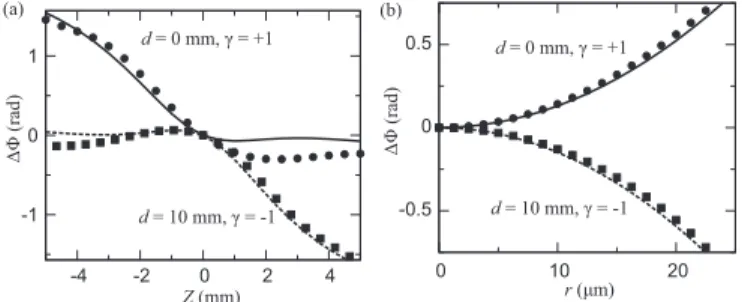
where the usefulness of lenses to focus few-cycle pulses is stressed. The symbols in Figs. 6(a) and 6(b) represent the CEP shift along the beam axis and along the focal plane, respectively, extracted from the numerically evaluated electric fields when the lens separation isd =0 mm andd =10, and the solid curves represent the predictions of Eq. (12) with g=0.5, C=0, andγ = ±1, demonstrating also the useful- ness of the separable doublet system for CEP map tailoring.
Additional calculations confirm applicability of the system with pulse durations down to 5-fs (two-cycle pulse). With
Z(mm)
ΔΦ (rad)
(a)
d = 0 mm, γ = +1
d = 10 mm, γ = -1 -1
0 1
-4 -2 0 2 4
-0.5 0 0.5
0 10 20
r(μm)
ΔΦ (rad)
(b)
d = 0 mm, γ = +1
d = 10 mm, γ = -1
FIG. 6. (a) On-axis CEP shift about the focus for two different lens separation distances evaluated from Eq. (14) (curves) and from the numerical simulation described in the text (symbols). (b) The same but on the focal plane.
shorter pulses, precompensation of higher-order dispersion terms than the second and third might be necessary to retain the pulse shape.
V. CONCLUSIONS
We have completed partial calculations provided by differ- ent authors in previous works in order to provide the com- plete spatial distribution of the CEP of few-cycle Gaussian- Gaussian pulsed beams focused by mirrors or lenses. This amounts to specify the complete electric field under the envelope at each position of the focal volume. Our results underscore the importance of characterizing the few-cycle laser source in use by measuring its factor g since it is the fundamental parameter that specifies the CEP map in the focal volume. Once g is determined, small residual chirps and small chromatic aberration can be used to modify and adapt the CEP map for specific applications or target posi- tions without appreciably deteriorating the pulse. We have shown, for example, how to suppress the CEP variation both longitudinally and transversally at different locations of the focal volume. We have also proposed and tested numerically a quasiachromatic doublet that can perform this job without distorting the few-cycle pulse and only changing the CEP map. This analysis or others more adapted to each particular situation can help to reach conditions that are beneficial in research areas where light-matter interactions strongly depend on the CEP, such as high-harmonic generation, attosecond- pulse production, ultrafast nano-optics, or plasmonics. As possible extensions of this paper, it would be of interest to remove the restriction to Gaussian beams in order to evaluate the CEP map of other focused beams in use in these phase- sensitive light-matter interactions, e.g., of vortex beams [42]
or radially or azimuthally polarized beams [43].
ACKNOWLEDGMENTS
We acknowledge the Spanish Ministerio de Economía y Competitividad Projects No. MTM2015-63914-P and No. FIS2017-87360-P. The ELI-ALPS Project (Project No.
GINOP-2.3.6-15-2015-00001) was supported by the Euro- pean Union and cofinanced by the European Regional Devel- opment Fund.
[1] F. Krausz and M. I. Stockman, Attosecond metrology: from electron capture to future signal processing,Nat. Photon.8,205 (2014).
[2] A. Baltuska, T. Udem, M. Uiberacker, M. Hentschel, E. Gouliel- makis, C. Gohle, R. Holzwarth, V. Yakovlev, A. Scrinzi, T. Hansch, and F. Krausz, Attosecond control of electronic processes by intense light fields, Nature (London) 422, 189 (2003);Nature421,611(2003).
[3] C. A. Haworth, L. E. Chipperfield, J. S. Robinson, P. L. Knight, J. P. Marangos, and J. W. G. Tisch, Half-cycle cutoffs in harmonic spectra and robust carrier-envelope phase retrieval, Nat. Phys.3,52(2007).
[4] N. Ishii, K. Kaneshima, K. Kitano, T. Kanai, S. Watanabe, and J. Itatani, Carrier-envelope phase-dependent high harmonic generation in the water window using few-cycle infrared pulses, Nat. Commun.5,3331(2014).
[5] M. Krüger, M. Schenk, and P. Hommelhoff, Attosecond con- trol of electrons emitted from a nanoscale metal tip, Nature (London)475,78(2011).
[6] M. Chini, K. Zhao, and Z. Chang, The generation, characteriza- tion and applications of broadband isolated attosecond pulses, Nat. Photon.8,178(2014).
[7] T. Popmintchev, M.-C. Chen, P. Arpin, M. M. Murnane, and H. C. Kapteyn, The attosecond nonlinear optics of bright coher- ent X-ray generation,Nat. Photon.4,822(2010).
[8] P. Rudawski, A. Harth, C. Guo, E. Lorek, M. Miranda, C. M.
Heyl, E. W. Larsen, J. Ahrens, O. Prochnow, T. Binhammer, U. Morgner, J. Mauritsson, A. L’Huillier, and C. L. Arnold, Carrier-envelope phase dependent high-order harmonic gener- ation with a high-repetition rate OPCPA-system, Eur. Phys. J.
D69,70(2015).
[9] C. Delfin, C. Altucci, F. De Filippo, C. de Lisio, M. B. Gaarde, A. L’Huillier, L. Roos, and C.-G. Wahlström, Influence of the medium length on high-order harmonic generation,J. Phys. B:
At., Mol. Opt. Phys.32,5397(1999).
[10] K. Kovács, E. Balogh, J. Hebling, V. Tosa, and K. Varjú, Quasi- Phase-Matching High-Harmonic Radiation Using Chirped THz Pulses,Phys. Rev. Lett.108,193903(2012).
[11] C. Altucci, R. Bruzzese, C. de Lisio, M. Nisoli, E. Priori, S.
Stagira, M. Pascolini, L. Poletto, P. Villoresi, V. Tosa, and K.
Midorikawa, Phase-matching analysis of high-order harmonics generated by truncated Bessel beams in the sub-10-fs regime, Phys. Rev. A68,033806(2003).
[12] T. Tritschler, K. D. Hof, M. W. Klein, and M. Wegener, Vari- ation of the carrier-envelope phase of few-cycle laser pulses owing to the Gouy phase: a solid-state-based measurement,Opt.
Lett.30,753(2005).
[13] Z. Yang, Z. Yang, and S. Zhang, Carrier-envelope phase of ultrashort pulsed Laguerre-Gaussian beam,Chin. Opt. Lett.6, 189 (2008).
[14] B. Major, Z. L. Horváth, and M. A. Porras, Phase and group velocity of focused, pulsed Gaussian beams in the presence and absence of primary aberrations,J. Opt.17,065612(2015).
[15] M. A. Porras, Characterization of the electric field of focused pulsed Gaussian beams for phase-sensitive interactions with matter,Opt. Lett.34,1546(2009).
[16] D. Hoff, M. Kruger, L. Maisenbacher, A. M. Sayler, G. G.
Paulus, and P. Hommelhoff, Tracing the phase of focused broadband laser pulses,Nat. Phys.13,947(2017).
[17] F. Lindner, G. G. Paulus, H. Walther, A. Baltuska, E. Gouliel- makis, M. Lezius, and F. Krausz, Gouy Phase Shift for Few- Cycle Laser Pulses,Phys. Rev. Lett.92,113001(2004).
[18] Z. Wang, Z. Zeng, R. Li, and Z. Xu, Measurement of Gouy phase shift by use of supercontinuum spectral interference, Chin. Opt. Lett.5, S183 (2007).
[19] B. Major, D. Nemes, M. A. Porras, Z. L. Horváth, and A. P.
Kovács, Carrier-envelope phase changes in the focal region:
propagation effects measured by spectral interferometry,Appl.
Opt.54,10717(2015).
[20] C. J. Zapata-Rodriguez and M. A. Porras, Controlling the carrier-envelope phase of few-cycle focused laser beams with a dispersive beam expander,Opt. Express16,22090(2008).
[21] M. A. Porras and P. Dombi, Freezing the carrier-envelope phase of few-cycle light pulses about a focus,Opt. Express17,19424 (2009).
[22] M. A. Porras, Z. L. Horvath, and B. Major, On the use of lenses to focus few-cycle pulses with controlled carrier–envelope phase,Appl. Phys. B: Lasers Opt.108,521(2012).
[23] M. A. Porras, B. Major, and Z. L. Horvath, Carrier-envelope phase shift of few-cycle pulses along the focus of lenses and mirrors beyond the nonreshaping pulse approximation: the ef- fect of pulse chirp,J. Opt. Soc. Am. B29,3271(2012).
[24] B. Major, Phase and polarization changes of pulsed Gaussian beams during focusing and propagation, Ph.D. thesis, Univer- sity of Szeged, 2016.
[25] W. Holgado, C. Hernández-García, B. Alonso, M. Miranda, F. Silva, O. Varela, J. Hernández-Toro, L. Plaja, H. Crespo, and I. J. Sola, Tunable high-harmonic generation by chromatic focusing of few-cycle laser pulses, Phys. Rev. A95, 063823 (2017).
[26] P. Salières, P. Antoine, A. de Bohan, and M. Lewenstein, Tem- poral and Spectral Tailoring of High-Order Harmonics,Phys.
Rev. Lett.81,5544(1998).
[27] Z. Chang, A. Rundquist, H. Wang, I. Christov, H. C. Kapteyn, and M. M. Murnane, Temporal phase control of soft-x-ray harmonic emission,Phys. Rev. A58,R30(R)(1998).
[28] D. G. Lee, J.-H. Kim, K.-H. Hong, and C. H. Nam, Coherent Control of High-Order Harmonics with Chirped Femtosecond Laser Pulses,Phys. Rev. Lett.87,243902(2001).
[29] J. Mauritsson, P. Johnsson, R. López-Martens, K. Varjú, W.
Kornelis, J. Biegert, U. Keller, M. B. Gaarde, K. J. Schafer, and A. L’Huillier, Measurement and control of the frequency chirp rate of high-order harmonic pulses,Phys. Rev. A70, 021801 (2004).
[30] W. Holgado, C. Hernández-García, B. Alonso, M. Miranda, F.
Silva, L. Plaja, H. Crespo, and I. J. Sola, Continuous spectra in high-harmonic generation driven by multicycle laser pulses, Phys. Rev. A93,013816(2016).
[31] T. Goswami, S. K. Kumar, A. Dutta, and D. Goswami, Control of laser induced molecular fragmentation ofn-propyl benzene using chirped femtosecond laser pulses,Chem. Phys.360,47 (2009).
[32] S. Vidal, J. Degert, M. Tondusson, E. Freysz, and J. Oberlé, Optimized terahertz generation via optical rectification in ZnTe crystals, J. Opt. Soc. Am. B31,149(2014).
[33] E. Karimi, C. Altucci, V. Tosa, R. Velotta, and L. Marrucci, Influence of generalized focusing of few-cycle Gaussian pulses in attosecond pulse generation, Opt. Express21,24991(2013).
[34] D. Hoff, M. Krüger, L. Maisenbacher, G. G. Paulus, P. Hom- melhoff, and A. M. Sayler, Using the focal phase to control attosecond processes,J. Opt.19,124007(2017).
[35] A. E. Siegman, Defining, measuring, and optimizing laser beam quality,Proc. SPIE1868,2(1993).
[36] M. A. Porras, Diffraction effects in few-cycle optical pulses, Phys. Rev. E65,026606(2002).
[37] M. Nisoli, S. Stagira, S. D. Silvestri, O. Svelto, S. Sartania, Z. Cheng, G. Tempea, C. Spielmann, and F. Krausz, Toward a terawatt-scale sub-10-fs laser technology,IEEE J. Sel. Topics Quantum Electron.4,414(1998).
[38] M. Nisoli, S. Stagira, S. De Silvestri, O. Svelto, S. Sartania, Z.
Cheng, M. Lenzner, C. Spielmann, and F. Krausz, A novel-high energy pulse compression system: generation of multigigawatt sub-5-fs pulses,Appl. Phys. B65,189(1997).
[39] M. Nisoli, E. Priori, G. Sansone, S. Stagira, G. Cerullo, S. De Silvestri, C. Altucci, R. Bruzzese, C. de Lisio, P. Villoresi, L.
Poletto, M. Pascolini, and G. Tondello, High-Brightness High- Order Harmonic Generation by Truncated Bessel Beams in the Sub-10-fs Regime,Phys. Rev. Lett.88,033902(2002).
[40] M. Lewenstein, P. Balcou, M. Y. Ivanov, A. L’Huillier, and P. B. Corkum, Theory of high-harmonic generation by low- frequency laser fields,Phys. Rev. A49,2117(1994).
[41] Z. Bor and Z. L. Horváth, Distortion of femtosecond pulses in lenses. Wave optical description, Opt. Commun. 94, 249 (1992).
[42] D. Gauthier, P. R. Ribic, G. Adhikary, A. Camper, C. Chap- puis, R. Cucini, L. F. DiMauro, G. Dovillaire, F. Frassetto, R. Géneaux, P. Miotti, L. Poletto, B. Ressel, C. Spezzani, M.
Stupar, T. Ruchon, and G. De Ninno, Tunable orbital angular momentum in high-harmonic generation, Nat. Commun. 8, 14971(2017).
[43] D. P. Biss and T. G. Brown, Polarization-vortex-driven second- harmonic generation,Opt. Lett.28,923(2003).