Utilizing of Phase Shift Transformer for increasing of Total Transfer Capacity
Zsolt Čonka, Michal Kolcun, Gyӧrgy Morva
Technical University of Košice, Department of Electric Power Engineering, Mäsiarska 74, 040 01 Košice, Slovakia
Óbuda University, Bécsi út 96/b, 1034 Budapest, Hungary, morva@uni-obuda.hu
Abstract: The Construction of new international power lines is a very expensive and time- consuming task. The use of specialized equipment that can increase the Total Transfer Capacity can replace the need to construct new lines. One such device is a Phase Shift Transformer (PST). By optimal distribution of power flow on transmission lines we could increase TTC on profile. Detailed analysis is presented for Slovakia – Hungary and Slovakia – Czech interconnections in the Central East Europe network. Simulation results with and without PST are used to analyse the impact of PST on the TTC between Slovakia – Hungary and Slovakia – Czech interconnection.
Keywords: phase shift transformer; total transfer capacity; FACTS
1 Introduction
In densely interconnected power systems such as ENTSO-E, the physical power flows differ from the planned power exchanges. This leads to overloaded interconnecting power lines. A possible solution could be the construction of new lines or the use of special equipment that allows us to regulate the power flow thus Net Transfer Capacity could be increased.
The power transmission capacity indicates how much power can be transferred between two power systems without endangering the systems’ security. The perfect calculation of the transmission capacity is very important even for daily operation as well as on the electricity market. Both the operators and planners need to consider the maximal transfer capacity, system barriers and the amount of electricity that must be transferred.
Figure 1
Power surplus in Central Eastern Europe’s power system [13]
The calculation of transmission capacity should be repeated several times, in order to prevent inaccuracies in the calculation and thus prevent possible overloading of equipment, loss of stability or even the accidental damage of equipment.
Inaccurate estimates of transfer capacity leads to the unnecessary reduction of the amount of transmitted power, and it is inefficient use of networks.
Amount and diversity of the regulatory returns are also increased by power transfer. In fact, the electricity market is enormously competitive. There is a very strong economic impulse to improve the accuracy and efficiency of the calculation of the transport capacity for use by system operators, designers and energy traders [1].
The difference between physical flows and programmed exchanges leads to overloaded interconnecting lines between Slovakia and Hungary and subsequently between Slovakia and the Czech Republic. It also leads to increasing the amount of regulatory returns. Figure 2 shows the power flow across Slovakia’s power system. There are several ways to increase transfer capacity between the two power systems. One way is to build new power lines, but this is quite a time- consuming task. Another way is to utilize special devices which are especially designed to improve transfer capacity of existing power lines. One of the most promising devices, is the Phase Shift Transformer (PST).
Figure 2
Power flow across Slovak Power system [1]
1.1 Total Transfer Capacity (TTC)
For establishing transmission margins and power transfer capacities between neighbouring power systems the following three terms are used:
Total Transfer Capacity (TTC) is the maximum exchange program between two areas compatible with operational security standards applicable at each system in future network conditions, generation and load patterns were known perfectly in advance.
Transmission Reliability Margin (TRM) is a safety margin that can handle uncertainties to calculate TTC values arising from:
1) Adverse deviations of physical flows during operation due to the physical load management of frequency,
2) Emergency exchanges between power systems to cope with unexpected unbalanced situations in real time,
3) Inaccuracies, faulty data collection.
Net Transfer Capacity (NTC) is defined as:
TRM TTC
NTC (1)
Net Transfer Capacity is the maximum amount of electricity that can be transferred which satisfies safety criteria N-1.
Total Transfer Capacity between two power systems determines the transmission system operators on both sides of the interconnection. The calculation of the transfer capacity includes more than just the capacities of the power lines. Due to the fact that the distribution of power flows between different components of TS, N-1 criterion must be fulfilled. N-1 criterion determines that the grid must remain in operation after unexpected loss of an unexpected element of the transmission system. The calculation of transfer capacity between two power systems is realized in both power systems’ operators on each side of the interconnection. By using simulation programs, the maximal feasible amount of electricity that can be transmitted may be calculated. If the results of each TSO differ from each other, the lower value is used.
The aim of this process is to put power into the electricity market, as high capacity as is possible, while still observing transmission system limits. The ability of transferring power is calculated for each state of operating conditions. This process also allows not only exchanges between power systems but also transfers within each sub-system.
This process also includes transient and static simulations in order to determine maximal feasible amount of electricity in eight directions through interconnection with maintaining N-1 criterion, voltage collapse, and overcurrent. Figure 3 below shows cross-border power exchange between the power systems [1], [2], [3], [4], [5] [14].
Figure 3
Cross-border import/export capacity [13]
1.2 Phase Shift Transformer
Phase shift transformer (PST) is often used to control active power flow at the interface between two large and solid independent networks. The control of active power flow is achieved by adjusting the phase angle of the voltages at the terminals where the PST is installed. These are very complicated power transformers with several windings and junctions [6].
Figure 4
Symmetric Phase Shift Transformer (PST) [6]
Generally, phase shift transformers are built for a transmission system consists of two terminals and three-phase units. The source terminal is the terminal where the power is injected into the transformer and the terminal where the power flows out from transformer I called load terminal. Changes in phase angle between the terminal voltages are carried out by injecting additional voltage into entering voltage. When the series winding injects additional voltage in source terminal into neutral input voltage, the phase angle of voltages between input and output terminals of PST changes. As a result, the direction of power flow also changes.
With an active control of injected amount of additional voltage, the power flow across the power line can be continuously controlled as well [6], [8], [9], [10].
1.3 TTC Calculation
The simulation below (Figure 5) contains four variants of interconnection between Slovakia and Czech Republic, three variants between Hungary and Slovakia and two variants between Slovakia and Hungary. In the enlarged power systems
400 kV interconnection lines are installed between Križovany (SK) and Gönyű (HU). All the possible variations were simulated on the 2014 Central Eastern Europe system model. Simulations were created by a simulation program namely:
NEPLAN.
Figure 5
Slovakian power system for 2014
1.1.1 Variant SK-CZ I
Table 1 below shows the values of total transfer capacity on the Slovakian - Czech cross border connection. This model includes all generators, branches, transformers and other transmission system elements. Simulations for this variant were made without phase shift transformer. The model shows the actual values of transfer capacities between Slovakia and the Czech Republic. All simulations have been complied with safety criterion N-1. The limit element for this case was the line V 270, when line V 404 was switched off.
Table 1
TTC values for variant SK-CZ I
Branch Line loads
[MW] TTC [MW] Limit element (N-1) 404 (Nošovice – Varín) -874
2527,4 270
(404) 424 (Sokolnice – Križovany) -533,2
497 (Sokolnice – Stupava) -909,3 280 (Sokolnice – Senica) -100,9 270 (Liskovec – P. Bystrica) -110
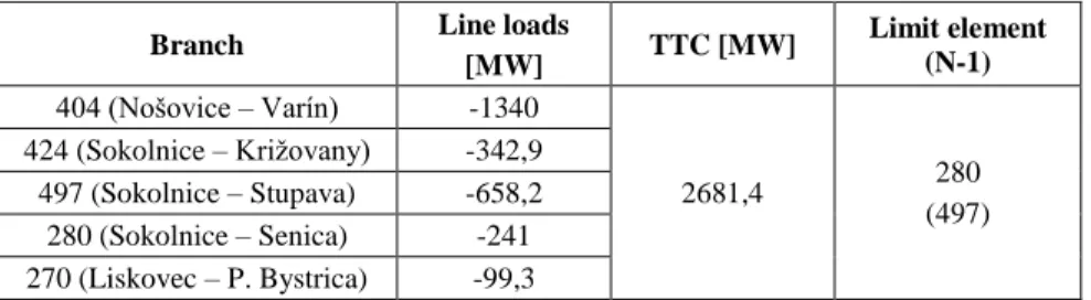
1.1.2 Variant SK-CZ II
Table 2 below shows the values of total transfer capacity on the Slovakian - Czech cross border connection with installed phase shift transformer on line V 404. In this case the simulations were created with phase shift transformer, and show the potential value of transfer capacities between Slovakia and the Czech Republic with PST installed on line V404. The simulations have been complied with safety criterion N-1. The limit element for this case was the line V 280, when line V 497 was switched off.
Table 2
TTC values for variant SK-CZ II
Branch Line loads
[MW] TTC [MW] Limit element (N-1) 404 (Nošovice – Varín) -1340
2681,4 280
(497) 424 (Sokolnice – Križovany) -342,9
497 (Sokolnice – Stupava) -658,2 280 (Sokolnice – Senica) -241 270 (Liskovec – P. Bystrica) -99,3 1.1.3 Variant SK-CZ III
Table 3 below shows the values of total transfer capacity on the Slovakian - Czech cross border connection with installed phase shift transformer on line V 424. The simulations for this variant have been accomplished with phase shift transformer, and show the potential value of transfer capacities between Slovakia and the Czech Republic with PST installed on line V424. The simulations have been complied with safety criterion N-1. The limit element for this case was the line V 270, when line V 407 was switched off.
Table 3
TTC values for variant SK-CZ III
Branch Line loads
[MW] TTC [MW] Limit element (N-1) 404 (Nošovice – Varín) -582,8
2698,4 270
(404) 424 (Sokolnice – Križovany) -1298,4
497 (Sokolnice – Stupava) -494,2 280 (Sokolnice – Senica) -171 270 (Liskovec – P. Bystrica) -152
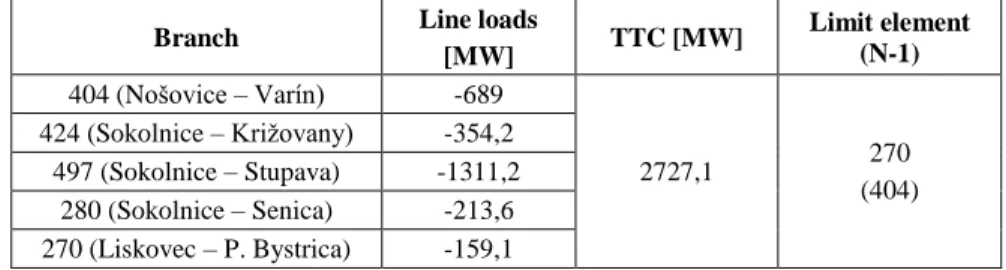
1.1.4 Variant SK-CZ IV
Table 4 below shows the values of total transfer capacity on the Slovak - Czech cross border connection with installed phase shift transformer on line V 497. The simulations for this variant have been accomplished with phase shift transformer, and shows the potential value of transfer capacities between Slovakia and the Czech Republic with PST installed on line V497. Simulations have been complied with safety criterion N-1. The limit element for this case was the line V 270, when line V 404 was turned off.
Table 4
TTC values for variant SK-CZ IV
Branch Line loads
[MW] TTC [MW] Limit element (N-1) 404 (Nošovice – Varín) -689
2727,1 270
(404) 424 (Sokolnice – Križovany) -354,2
497 (Sokolnice – Stupava) -1311,2 280 (Sokolnice – Senica) -213,6 270 (Liskovec – P. Bystrica) -159,1 1.1.5 Variant SK-HU I
Table 5 below shows the values of total transfer capacity on Slovakian - Hungarian cross border connection. This model includes all generators, branches, transformers and other transmission system elements. The simulations for this variant have been accomplished without phase shift transformer, and show the actual values of transfer capacities between Slovakia and Hungary. Simulations have been complied with safety criterion N-1. The limit element for this case was the line V 448, when line V 449 was switched off.
Table 5
TTC values for variant SK-HU I
Branch Line loads
[MW] TTC [MW] Limit element (N-1) 448 (Gabčíkovo-Györ) 1089,5
1946,7 448
(449) 449 (Levice-Göd) 857,2
1.1.6 Variant SK-HU II
Table 6 below shows the values of total transfer capacity on Slovakian - Hungarian cross border connection with installed phase shift transformer on line V 449. Simulations for this variant have been accomplished with phase shift transformer, and show the potential value of transfer capacities between Slovakia
and Hungary with PST installed on line V449. The limit element for this case was the line V 490, when line V 491 was switched off.
Table 6
TTC values for variant SK-HU II
Branch Line loads
[MW] TTC [MW] Limit element (N-1) 448 (Gabčíkovo-Györ) 1089,5
2394 490
(491) 449 (Levice-Göd) 1304,5
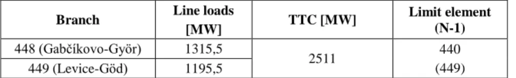
1.1.7 Variant SK-HU III
Table 7 below shows the values of total transfer capacity on Slovakian - Hungarian cross border connection with installed phase shift transformer on line V 449. The Simulations for this variant have been accomplished with phase shift transformer, and shows the potential value of transfer capacities between Slovakia and Hungary with PST installed on line V448. The limit element in this case was the line V 440, when line V 449 was turned off.
Table 7
TTC values for variant SK-HU III
Branch Line loads
[MW] TTC [MW] Limit element (N-1) 448 (Gabčíkovo-Györ) 1315,5
2511 440
(449) 449 (Levice-Göd) 1195,5
1.1.8 Variant SK-HU IV
Table 8 below shows the values of total transfer capacity on Slovakian – Hungarian cross border connections without any installed phase shift transformer.
The power system was enlarged by a new 400 kV line (V 400) from Križovany (Slovakia) and Gönyű (Hungary). Simulations for this variant have been accomplished without any phase shift transformer, and show the potential value of transfer capacities between Slovakia and Hungary with the new 400 kV line. The limit element for this case was the line V 440, when line V 449 was switched off.
Table 8
TTC values for variant SK-HU IV
Branch Line loads
[MW] TTC [MW] Limit element
(N-1) 448 (Gabčíkovo-Györ) 762,5
2779,4 449
(440) 449 (Levice-Göd) 1226,8
400 (Križovany-Gonyu) 790,1
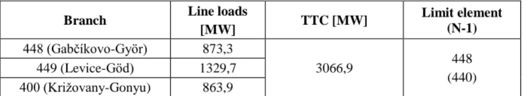
Table 9 below shows the values of total transfer capacity of enlarged Slovakian - Hungarian cross border connections with installed phase shift transformer on line 449. Simulations for this variant shows the potential value of transfer capacities between Slovakia and Hungary with a new 400 kV line and phase shift transformer. The limit element for this case was the line V 440, when line V 448 was switched off.
Table 9
TTC values for variant SK-HU V
Branch Line loads
[MW] TTC [MW] Limit element
(N-1) 448 (Gabčíkovo-Györ) 873,3
3066,9 448
(440) 449 (Levice-Göd) 1329,7
400 (Križovany-Gonyu) 863,9 Conclusions
The simulations’ results suggest new ways of increasing transfer capacity between Slovakia and Hungary as well as between Slovakia and Czech Republic. The results also show that the most suitable location of a phase shift transformer would be in the Slovakian power system. The best place for installing a PST transformer on cross-border connection would be between Slovakia and the Czech Republic, on line 497. The value of total transfer capacity with PST installed on line 497 was 2727,1 MW. The total transfer capacity with PST installed on line 424 was 2698,4 MW, and the value of total transfer capacity with phase shift transformer on line 404 was 2681,4 MW.
The most suitable location for installing a phase shift transformer on inter- connection between Slovakia and Hungary was on line V448. The value of total transfer capacity with a phase shift transformer installed on line 448 was 2511 MW. The total transfer capacity with PST installed on line 449 was 2394 MW.
Enlarging the power system by adding an interconnection line between Slovakia and Hungary has caused an increase of TTC from 1946,7 MW to 2779,4 MW. By installing PST in series with line 449 has increased TTC up to 3066,9 MW.
Acknowledgement
This work was supported by the Slovakian Research Agency No. VEGA 1/0388/13 project.
References
[1] I. Dobson, S. Green, R. Rajaraman, Ch. L. DeMarco, F. L. Alvarado, R.
Zimmerman.: Electric Power Transfer Capability: Concepts, Applications, Sensitivity, Uncertainty, Power Systems Engineering Research Center
November 2001 online [12.05.2015]
<http://www.pserc.cornell.edu/tcc/tutorial/TCC_Tutorial.pdf>
[2] Calculation methods online [12.05.2015] <http://www.elia.be/en/products- and-services/cross-border-mechanisms/transmission-capacity-at-
borders/calculation-methods>
[3] Ministry of Economy of Slovak Republic: Návrh Energetickej politiky Slovenskej republiky, May 2014 Online: cit.[19. feb. 2015]
<http://www.rokovania.sk/File.aspx/ViewDocumentHtml/ Mater-Dokum- 165253?prefixFile=m_>
[4] FAQ CEPS, a.s. online [19. Feb. 2015]
<http://www.ceps.cz/ENG/Media/Pages/FAQ.aspx>
[5] Definitions of Transfer capacities in liberalised Electricity Markets online
[19. Feb. 2015]
<https://www.entsoe.eu/fileadmin/user_upload/_library/ntc/entsoe_transfer CapacityDefinitions.pdf>
[6] C. Grande-Moran: Phase-shifting Transformer Modeling in PSS®E online [12.05.2015]
<http://ewh.ieee.org/soc/pes/newyork/NewSite/PDFs/Protection%20Relate d/Phase_Shifting_Transformer_Modeling.pdf>
[7] ENTSO-E, Network Code on Capacity Allocation and Congestion Management, September 2012
[8] ENTSO-E, Network Code on Forward Capacity Allocation, October 2013 [9] K. Noháč, L. Noháčová: Detekce nestandardních stavů v sítích s
obnovitelnými zdroji energie“. Proceedings of 7th International scientific symposium Elektroenergetika 2013, September 18-20, 2013, Stará Lesná, Slovakia
[10] M. Mešter, M. Hvizdoš : The fundamentals of wide area monitoring in power system. In: Energetika un elektrotehnika, 2005, Vol. 15, No. 4, pp.
110-115, ISSN 1407-7345
[11] R. Jakubčák, Ľ. Beňa, M. Kmec: Possibilities of Using Facts Devices In Power System. In: Acta Electrotechnica et Informatica. Roč. 13, č. 3 (2013), s. 8-11. - ISSN 1335-8243
[12] Program rozvoja SEPS, a.s., na roky 2011 – 2020. [online]. [cit.
08.08.2011]. Available on internet:
http://www.sepsas.sk/seps/Dokumenty/PR2020.pdf
[13] FAQ CEPS, a.s. online [19. Feb. 2015]
http://www.ceps.cz/ENG/Media/Pages/FAQ.aspx
[14] Z. Čonka, M. Kolcun: Impact of TCSC on the Transient Stability In: Acta Electrotechnica et Informatica. Roč. 13, č. 2 (2013), s. 50-54. - ISSN 1335- 8243 Available on internet :www.versita.com/aei. (2013)