* Corresponding author. E-mail address: bodzassandor@eng.unideb.hu Manuscript History:
Designing and Analysis of the TCA Parameters of a Bevel Gear Having Circular Tooth Direction in the Function of the Moment
Sándor Bodzás
Department of Mechanical Engineering, University of Debrecen, Hungary
Abstract
The aim of this publication is the designing and the CAD modelling of the Gleason – type bevel gear pair and the analysis of the connecting teeth in case of different load moments. The main properties of this gear pair are the changing whole depth along the face width and the circular tooth direction which is created by a complicated cutting tool. Cutting edges are situated along the perimeter of the middle circle by equal circular pitches on the cutting tool. After the creation of the CAD model, which could be created by numerical way, TCA could be done in the function of the moment changing. The normal stress, normal elastic strain and normal deformation will be analyzed on the surface of the driven gear perpendicularly for the tooth surface. Knowing of the results correlations will be visualized based on the TCA results and the load moments. The behavior of the contact teeth will be analyzed.
Keywords: Gleason, moment, bevel gear, TCA, CAD..
1. Introduction
The main properties of the bevel gears having arc tooth direction are [2, 4, 5, 8, 9, 12, 16 - 23]
the good labor productivity of the production, the economical production, the decreasing of the tool consumption and the improvement of the gearing quality
.
Figure 1. General sketch of the generation of the bevel gear having arc tooth direction.
Bevel gear having arc tooth direction could be manufactured by three methods (Figure 1) [2, 8, 18]:
rsRa
if rs=0, the tooth direction is a circle. This is the Gleason type circular tooth. The main property is the changing whole depth. These gears could be manufactured by division per tooth and generation.
if rs≠0, the tooth direction is epicycloid. In this case the whole depth is constant along the whole tooth length. They are the Fiat – Mammano, Oerlikon and Klingelnberg cycloid tooth methods.
if rs=∞, the tool circle will be a line which is rolling down on the Ra crown wheel.
The established tooth direction will be involute. This is the Klingelnberg – type involute tooth.
Bevel gear has bearing only on one shaft end that is why this shaft end could be done significant deformation due to the load. In case of bevel gear the shape of the tooth surface is barrel-shaped that is why the tooth connection could be swivel [1, 2, 4, 5, 8, 9, 12, 13]. Based on them this type of bevel gear has low noise, better lubrication conditions and tool life.
2. Gleason-type manufactrung method
Gleason Works has developed the first bevel gear working machine which is worked by division per tooth and generation per tooth. The tool is a face-mill cutter on which the cutting tools are situated along a circle. The distances between the cutting tools are equal (Figure 2) [2, 4, 8 - 13, 16 - 23].
Figure 2. The geometry of the Gleason-type gear head cutter [14] and the manufacturing process [15].
Figure 3. Bevel gear having changing whole depth along the generatix of the cone.
Head cutter
Bevel gear
Figure 4. The arrangement of the Gleason-type manufacturing machine [4].
The theoretical figure of the manufacturing process could be seen on Figure 3 and 4. The head cutter is kept by the cradle. This cradle could be moved around its own axis by a determined angle and speed. The workpiece is fixed to the work spindle. The vertex of a cone is overlapped with the center point of the crown wheel [2, 4, 8]. The plane which is established by the head edges of the cutter is tangential to the generatix of the root cone of the workpiece. The cutting edges of the head cutter is manufactured the teeth of the workpiece along a helical line by generating method. After one tooth generation, when the manufactured tooth is not contact with the cutter, the workpiece is turned by one tooth pitch automatically. After that the generation process could be repeated. Based on this the circular gearing process is a discontinuous method [2, 4, 7, 8, 11, 12, 13, 16 - 23].
The process is ensured high cutting power because of the cutter having more cutting inserts. If the number of cutting inserts around the circle is increased the surface quality of the generated teeth will be improved [2, 4, 7, 8, 11, 12, 13, 16 - 23].
3. Determination of the tooth profile and tooth direction by mathematical way
Knowing of the geometry of the major cutting edge of the head cutter the rg
,,
generation curve of the major cutting edge is given in the Kg (ζ, η, ξ) coordinate system (Figure 5). Rotation motion has to be ensured for the head cutter:𝑟⃗
2𝑅= 𝑀
2𝑅,𝑔∙ 𝑟⃗
𝑔(1)
The transformation between the 𝑟⃗2𝑅 rotation and the 𝑟⃗2𝑆 stationary coordinate systems is [10, 11]
𝑟⃗
2𝑆= 𝑀
2𝑆,2𝑅∙ 𝑟⃗
2𝑅𝑀
2𝑅,𝑔= [
0 0 1
𝑅2𝑚1 0 0 0 0
0 1 0
0 0
0 1 ]
𝑀
2𝑆,2𝑅= [
𝑐𝑜𝑠(𝜑
2) −𝑠𝑖𝑛(𝜑
2) 0 0 𝑠𝑖𝑛(𝜑
2) 𝑐𝑜𝑠(𝜑
2) 0 0
0 0
0 0
1 0
0 1 ]
(2)
(4)
(3)
Figure 5. Determination of the major cutting edge of the head cutter.
H
Ot P
r1R
z
2Sz
2Rx
2Sx
2RO2RO2s rg
ORm
Ot
x
2Sx
2R
y
2Sy
2R
O2RO2s
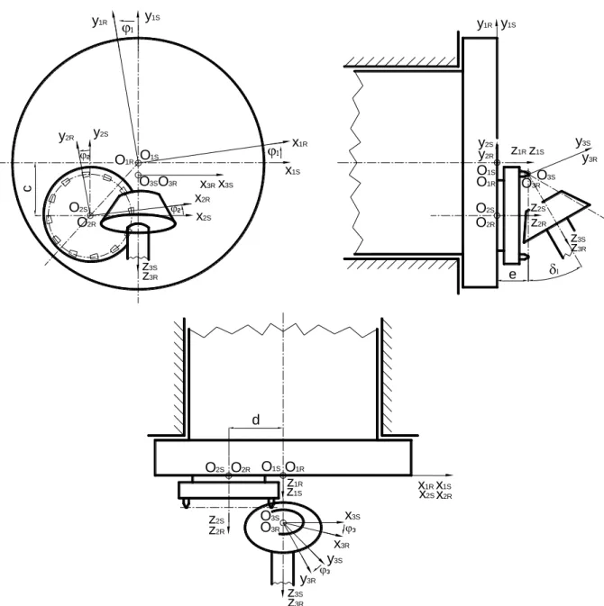
Figure 6. The mathematical description of the manufacturing process.
The total mathematical description of the manufacturing process of the Gleason method could be seen on Figure 6.
According to (1) - (4) the motion expressions of the head cutter could be written by mathematical way (Figure 5) [10, 11]. Knowing of the motion of the cradle, the necessary transformation matrix is
𝑀
1𝑅,1𝑆= [
𝑐𝑜𝑠(𝜑
1) 𝑠𝑖𝑛(𝜑
1) 0 0
−𝑠𝑖𝑛(𝜑
1) 𝑐𝑜𝑠(𝜑
1) 0 0 0
0
0 0
1 0
0 1 ]
where:
y1R y1S
x1S
x1R
y1R y1S
z1Rz1S
y2S
x2S
y2R
x2R
y2S y2R
z2S
z2R
z3S
z3R
y3S
y3R
z3S
z3R
x3S
x3R O2S
O2R
O1S O1R
O2S O2R O1S
O1R O3S
O3R
O3SO3R
c
e l
z2S z2R
x2Sx2R z1R
z1S x1Rx1S
z3S z3R
x3R x3S
y3S y3R
O3S O3R O2S O2R O1SO1R
d
(5)
𝑀
1𝑆,2𝑆= [
1 0 0 −𝑑 0 1 0 −𝑐 0
0 0 0
1 0
0 1
]
Taking into consideration the correlation between the velocity vectors of the relative movement in K1R and K3R coordinate systems [2, 3, 10, 11]:
→
𝑣 1𝑅(12)
= 𝑀
1𝑅,3𝑅∙
→
𝑣 3𝑅 (12)in K1R coordinate system, the relative velocity vector, based on (7) is [2, 3, 10, 11]:
→
𝑣 3𝑅 (12)= 𝑑
𝑑𝑡 →
𝑟3𝑅
= 𝑑
𝑑𝑡 (𝑀
3𝑅,1𝑅)
→
𝑟 1𝑅→
𝑣 1𝑅(12)
= 𝑀
1𝑅,3𝑅∙ 𝑑
𝑑𝑡 (𝑀
3𝑅,1𝑅)
→
𝑟 1𝑅where P1k is the kinematic mapping matrix [2, 3, 10, 11]:
𝑃
1𝑘= 𝑀
1𝑅,3𝑅∙ 𝑑
𝑑𝑡 (𝑀
3𝑅,1𝑅)
On the tooth surfaces of the meshing teeth, it can be defined - as contact points on surfaces mutually covering each other - by solving the connection equation - which expresses the 1st Law of Contact - and the vector-scalar function simultaneously [1, 2, 3, 6, 10, 11]:
→
𝑛 1𝑅∙
→
𝑣 1𝑅 (12)=
→
𝑛 3𝑅∙
→
𝑣 3𝑅 (12)=
→ ∙
𝑛→
𝑣(12)Knowing of the mathematical description the designing of the bevel gear having circular tooth direction could be realized (Figure 7) in general case. A bevel gear pair having concrete geometry has been designed and the CAD models of the gear pairs have been created because of the geometric analysis, the connection development and TCAs (Figure 7, Figure 8 and Table 1).
a) driving gear b) driven gear
(7)
(8)
(9)
(11)
(10)
c) assembly models
Figure 7. The CAD models of the generated bevel gear pair.
Figure 8. The main parameters of the bevel gear.
b
Re
dae de
hf ha
a
f
dfe
f
a
dm
b/2
di
dfi dai
Ri
Rm
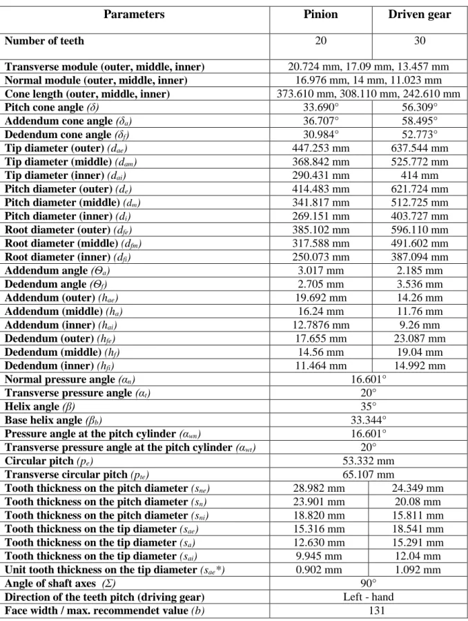
Table 1 The calculated parameters of the designed bevel gear pair
Parameters Pinion Driven gear
Number of teeth 20 30
Transverse module (outer, middle, inner) 20.724 mm, 17.09 mm, 13.457 mm Normal module (outer, middle, inner) 16.976 mm, 14 mm, 11.023 mm Cone length (outer, middle, inner) 373.610 mm, 308.110 mm, 242.610 mm
Pitch cone angle (δ) 33.690° 56.309°
Addendum cone angle (δa) 36.707° 58.495°
Dedendum cone angle (δf) 30.984° 52.773°
Tip diameter (outer) (dae) 447.253 mm 637.544 mm
Tip diameter (middle) (dam) 368.842 mm 525.772 mm
Tip diameter (inner) (dai) 290.431 mm 414 mm
Pitch diameter (outer) (de) 414.483 mm 621.724 mm
Pitch diameter (middle) (dm) 341.817 mm 512.725 mm
Pitch diameter (inner) (di) 269.151 mm 403.727 mm
Root diameter (outer) (dfe) 385.102 mm 596.110 mm
Root diameter (middle) (dfm) 317.588 mm 491.602 mm
Root diameter (inner) (dfi) 250.073 mm 387.094 mm
Addendum angle (Ѳa) 3.017 mm 2.185 mm
Dedendum angle (Ѳf) 2.705 mm 3.536 mm
Addendum (outer) (hae) 19.692 mm 14.26 mm
Addendum (middle) (ha) 16.24 mm 11.76 mm
Addendum (inner) (hai) 12.7876 mm 9.26 mm
Dedendum (outer) (hfe) 17.655 mm 23.087 mm
Dedendum (middle) (hf) 14.56 mm 19.04 mm
Dedendum (inner) (hfi) 11.464 mm 14.992 mm
Normal pressure angle (αn) 16.601°
Transverse pressure angle (αt) 20°
Helix angle (β) 35°
Base helix angle (βb) 33.344°
Pressure angle at the pitch cylinder (αwn) 16.601°
Transverse pressure angle at the pitch cylinder (αwt) 20°
Circular pitch (pe) 53.332 mm
Transverse circular pitch (pte) 65.107 mm
Tooth thickness on the pitch diameter (sne) 28.982 mm 24.349 mm Tooth thickness on the pitch diameter (sn) 23.901 mm 20.08 mm Tooth thickness on the pitch diameter (sni) 18.820 mm 15.811 mm Tooth thickness on the tip diameter (sae) 15.316 mm 18.541 mm Tooth thickness on the tip diameter (sa) 12.630 mm 15.291 mm Tooth thickness on the tip diameter (sai) 9.945 mm 12.04 mm Unit tooth thickness on the tip diameter (sae*) 0.902 mm 1.092 mm
Angle of shaft axes (Σ) 90°
Direction of the teeth pitch (driving gear) Left - hand
Face width / max. recommendet value (b) 131
4. Tooth contact analysis
The aim of the TCA is the determination of the mechanical parameters of the tooth contact zone. Based on the determined parameters the modification of the geometric parameters could be done because of the favourable TCA results [1, 6, 10].
4.1. Determination of the material quality and the finite element mesh
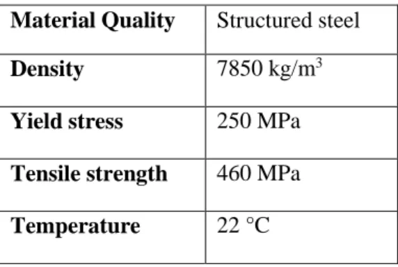
The property of the material used for the analysed mating bevel gear is defined in Table 2.
Table 2 Defining the material properties Material Quality Structured steel
Density 7850 kg/m3
Yield stress 250 MPa Tensile strength 460 MPa Temperature 22 °C
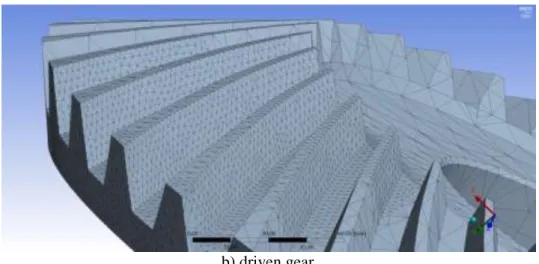
During defining the finite element mesh in the contact zone, sphere volume (80 mm radius) that consists of dense triangles (2 mm mesh dimension) has been applied on the toothed area (Figure 9).
The friction coefficient in the tooth contact zone is μ=0.15.
a) pinion gear
b) driven gear
Figure 9. Defining of the finite element mesh.
4.2. Setting the loads and boundary conditions
During the analyses, the gear having less number of teeth (pinion) drives the gear having more number of teeth. 5 degrees of freedom were fixed of the pinion gear wheel, only the rotation along the rotational axis was allowed. The pinion wheel was loaded by M=800 - 1200 Nm of moment by 100 Nm steps. 6 degrees of freedom of the driven gear were fixed.
Normal mechanical values have been detected which are perpendicular for the tooth surfaces as an effect of the different loads, on the tooth surfaces of the pinion and driven gear wheels. During the connection more tooth pairs are connected. We have analysed the first contact zone when the difference teeth are stepped into the contact area. The established TCA parameters have been analysed on the tooth surface of the driven gear.
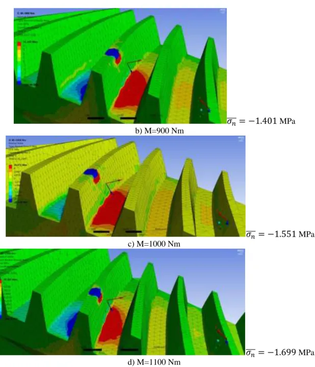
4.3. Normal stress analysis
The finite element results of the normal stress in the function of the moment are shown on Figure 10. Results are shown on a diagram (Figure 11). In absolute value, as an effect of the increasing load moment, normal stress values also increase on the tooth surfaces of the driven gear in absolute value (Figure 11).
𝜎
𝑛̅̅̅ = −1.24
MPa a) M=800 Nm𝜎
𝑛̅̅̅ = −1.401
MPa b) M=900 Nm𝜎
𝑛̅̅̅ = −1.551
MPa c) M=1000 Nm𝜎
𝑛̅̅̅ = −1.699
MPa d) M=1100 NmFigure 10. Normal stress values as an effect of load moment on the surface of the driven gear.
Figure 11. Load – normal stress diagram.
4.4. Normal elastic strain analysis
The finite element results of the normal elastic strain in the function of the moment are shown in Figure 12.
𝜀
𝑛̅̅̅ =
-0.0000219 mm a) M=800 Nm𝜀
𝑛̅̅̅ =
-0.0000249 mm𝜀
𝑛̅̅̅ =
-0.0000275 mm c) M=1000 Nm𝜀
𝑛̅̅̅ =
-0.00003 mm d) M=1100 Nm𝜀
𝑛̅̅̅ =
-0.0000326 mm
e) M=1200 NmFigure 12. Normal elastic strain values as an effect of load moment on the surface of the driven gear.
Results are shown on a diagram (Figure 13). In absolute value, as an effect of the increasing load moment, normal elastic strain values also increase on the tooth surfaces of the driven gear in absolute value.
Figure 13 Load – normal elastic strain diagram.
4.5. Normal deformation analysis
The finite element results of the normal deformation in the function of the moment are shown on Figure 14.
𝑢 ̅̅̅ =
𝑥 -0.0243 mm a) M=800 Nm𝑢
𝑥̅̅̅ =-0.0274 mm
𝑢
𝑥̅̅̅ =-0.0304 mm c) M=1000 Nm
𝑢
𝑥̅̅̅ =-0.0333 mm d) M=1100 Nm
𝑢
𝑥̅̅̅ =-0.0363 mm e) M=1200 Nm
Figure 14. Normal deformation values as an effect of load moment on the surface of the driven gear.
Results are shown on a diagram (Figure 15). In absolute value, as an effect of the increasing load moment, normal deformation values also increase on the tooth surfaces of the driven gear in absolute value.
Figure 15 Load – normal deformation diagram
Conclusion
The type of the bevel gears having arc tooth direction was analyzed. According to the type of the cutting tool and the applied manufacturing technology three main types of bevel gear having arc tooth direction are differentiated.
In case of the Gleason-type manufacturing method the tooth direction is circular arc. During the process the head cutter is done rotation motion around its own axes and the axis of rotation of the cradle while the workpiece is done discreet rotation motion by the steps of the number of teeth. This technology could be described by mathematical way which is necessary for the technological analysis, the geometric designing and the creation of the CAD models of the bevel gear pairs. Naturally an own computer software has been developed because of the facilitation of the calculations and the designing. This process could be used for many types of Gleason’s bevel gears in general case.
A bevel gear pair having arc profile and concrete geometry has been designed. The CAD models have been created by SolidWorks software. After the part designing the geometrical correct assembly could be done.
This gear pair has been loaded by different moment continuously. The received TCA parameters have been analyzed on the tooth contact zone on the surface of the driven gear by Ansys software. These parameters have been determined perpendicularly for the tooth surfaces.
Linear and increasing correlations have been achieved among the moment and the analyzed TCA parameters (normal stress, normal deformation and normal elastic strain).
Acknowledgements
This research was supported by the János Bolyai Research Scholarship of the Hungarian Academy of Sciences.
References
[1] Argyris, J., Fuentes, A., & Litvin, F. L. (2002). Computerized Integrated Approach for Design and Stress Analysis of Spiral Bevel Gears. Computer Methods in Applied Mechanics and Engineering, Vol. 191 No.11-12, 1057-1095.
[2] Dudás, I. (2011). Gépgyártástechnológia III., A. Megmunkáló eljárások és szerszámaik, B. Fogazott alkatrészek gyártása és szerszámaik. Műszaki Kiadó
[3] Dudás, L. (1991). Kapcsolódó felületpárok gyártásgeometriai feladatainak megoldása az elérés modell alapján. Kandidátusi Tézisek, Budapest, TMB, 144.
[4] Dudley, D. W. Gear Handbook,(1962). McGraw-Hill Book Company [5] Erney,Gy. (1983). Fogaskerekek. Műszaki Könyvkiadó, Budapest, 460.
[6] Fuentes, A., Iserte, J. L., Gonzalez-Perez, I., & Sanchez-Marin, F. T. (2011). Computerized design of advanced straight and skew bevel gears produced by precision forging. Computer Methods in Applied Mechanics and Engineering, Vol. 200, No.29-32, 2363-2377
[7] Gupta, K., Jain, N. K., & Laubscher, R. (2017). Advanced gear manufacturing and finishing: classical and modern processes. Academic Press
[8] Héberger, K., Iliász, D., Rezek, Ö., Tóth, I. (1981): A Gépgyártás Technológiája, Iii. Tömeggyártás, Negyedik Kiadás, Tankönyvkiadó, Budapest, 462.
[9] Klingelnberg, J. (2016). Fundamentals of Bevel Gears. In Bevel Gear (pp. 11-56). Springer Vieweg, Berlin, Heidelberg.
[10] Litvin, F. L., & Fuentes, A. (2004). Gear geometry and applied theory. Cambridge University Press.
[11] Litvin, F. L. (1972). A fogaskerékkapcsolás elmélete. Műszaki Könyvkiadó.
[12] Rohonyi V.(1980): Fogaskerékhajtások. Műszaki Könyvkiadó, Budapest.
[13] Terplán Z. (1975). Gépelemek Iv., Kézirat, Tankönyvkiadó, Budapest, 220.
[14] https://www.ebay.com/itm/7-5-Gleason-Ridg-Ac-Gear-Cutter-Head-No-30207009-24-Blade- /261313074965
[15] http://mansourfahmi.com/en
[16] Marciniec, A., Pacana, J., Pisula, J. M., & Fudali, P. (2018). Comparative analysis of numerical methods for the determination of contact pattern of spiral bevel gears. Aircraft Engineering and Aerospace Technology, Vol. 90, No.2, 359-367.
[17] Álvarez, Á., Calleja, A., Ortega, N., & de Lacalle, L. (2018). Five-axis milling of large spiral bevel gears:
toolpath definition, finishing, and shape errors. Metals, Vol. 8, No.5, 353.
[18] Tsiafis, I., Mamouri, P., & Kompogiannis, S. (2018, July). Design and manufacturing of spiral bevel gears using CNC milling machines. In IOP Conference Series: Materials Science and Engineering (Vol. 393, No. 1, p. 012066). IOP Publishing.
[19] Feng, L. Y., Tian, M. Y., Liu, C. H., Liu, T., & Ma, Z. H. (2011). An Auto—Design System of Gleason Spiral Bevel Gear. In Advanced Materials Research (Vol. 317, 62-65). Trans Tech Publications.
[20] Garcia-Garcia, R., & Gonzalez-Palacios, M. A. (2018). Method for the geometric modeling and rapid prototyping of involute bevel gears. The International Journal of Advanced Manufacturing Technology, 98(1-4), 645-656.
[21] Li, J.B., Ma, H.J., Deng, X.Z., Zhang, H., Yang, J.J., Xu, K., Li, T.X., Xu, A.J. and Wang, H.L. (2017). An approach to realize the networked closed-loop manufacturing of spiral bevel gears. The International Journal of Advanced Manufacturing Technology, Vol. 89, No.5-8, 1469-1483.
[22] Marciniec, A., & Sobolewski, B. (2015). Modeling and simulation of bevel gearboxes in cad environment.
Diagnostyka, 16.
[23] Pisula, J., & Płocica, M. (2014). Methodology of designing the geometry of the bevel gear using numerical simulation to generate the teeth flank surfaces. acta mechanica et automatica, Vol.8, No.1, 5-8.

![Figure 2. The geometry of the Gleason-type gear head cutter [14] and the manufacturing process [15]](https://thumb-eu.123doks.com/thumbv2/9dokorg/1067199.70872/3.892.112.494.124.708/figure-geometry-gleason-type-gear-cutter-manufacturing-process.webp)
![Figure 4. The arrangement of the Gleason-type manufacturing machine [4].](https://thumb-eu.123doks.com/thumbv2/9dokorg/1067199.70872/4.892.238.640.152.594/figure-arrangement-gleason-type-manufacturing-machine.webp)