Conference on Modelling Fluid Flow (CMFF’18) The 17th International Conference on Fluid Flow Technologies Budapest, Hungary, September 4-7, 2018
E FFECT OF STREAMWISE AND TRANSVERSE DAMPING ON FLOW AROUND AN ELASTICALLY SUPPORTED CYLINDER
Dániel DOROGI
1, László BARANYI
21 Corresponding Author. Department of Fluid and Heat Engineering, Faculty of Mechanical Engineering and Informatics, University of Miskolc. 3515 Miskolc-Egyetemváros, Hungary. Tel.: +35 46 565 111, Fax: +36 46 565 168, E-mail: aramdd@uni-miskolc.hu
2 Department of Fluid and Heat Engineering, Faculty of Mechanical Engineering and Informatics, University of Miskolc. E-mail:
arambl@uni-miskolc.hu
ABSTRACT
In this paper flow around a circular cylinder free to move in two-degrees-of-freedom is investigated numerically in the Reynolds number range of Re=80–240. Reynolds number is varied with the reduced velocity U* using Re=34.74U* and the mass ratio is fixed at m*=10. The main purpose of the study is to investigate the effects of streamwise and transverse damping values (ζx and ζy). Computations are carried out for different Re and U* pairs to investigate the separate effects of ζx and ζy. Although ζx has a negligible effect on flow parameters, at small transverse damping values a significant increase is identified in the mechanical energy transfer E and a substantial drop occurs in the root-mean-square and time-mean values of drag (CDrms and CDmean). Energy transfer is influenced mainly by transverse cylinder motion. Changes in the vortex structure are also identified. In addition, computations are carried out for different ζy (ζx=0) values with varying Re and U*.
Two-branch cylinder response and small E are observed for ζy=0.001 while high E is observed at larger but still low ζy values. At high ζy all quantities investigated become small. CDrms and CDmean curves plotted against Re shift downwards with increasing ζy.
Keywords: circular cylinder, damping coefficient, mechanical energy transfer, natural frequency, numerical simulation
NOMENCLATURE b [kg/s] damping
CD [-] drag coefficient, 2𝐹𝐷/(𝜌𝑈∞2𝑑) CL [-] lift coefficient, 2𝐹𝐿/(𝜌𝑈∞2𝑑) d [m] cylinder diameter, length scale FD [N/m] drag per unit length of cylinder FL [N/m] lift per unit length of cylinder FN [-] reduced natural frequency, fNd/U∞
fN [1/s] natural frequency of system k [N/m] spring stiffness
K [-] non-dimensional natural frequency, fNd2/ν
m [kg/m] mass of cylinder per unit length m* [-] mass ratio, 4m/(d2πρ)
R [-] radius, non-dimensionalised by d Re [-] Reynolds number, U∞d/ν
St0 [-] dimensionless vortex shedding frequency for a stationary cylinder t [-] time, non-dimensionalised by
d/U∞
U∞ [m/s] free stream velocity, velocity scale U* [-] reduced velocity, U∞/(fNd)
x, y [-] Cartesian coordinates, non- dimensionalised by d
x0, y0 [-] cylinder displacement in x and y directions, non-dimensionalised by d
ζ [-] structural damping coefficient, 𝑏/(2√𝑚𝑘)
ν [m2/s] kinematic viscosity of fluid ρ [kg/m3] fluid density
Subscripts and Superscripts L, D lift, drag
rms root-mean-square value mean time-mean values
x, y streamwise and transverse directions 1,2 on cylinder surface, at outer boundary of
domain
0 refers to cylinder response (x0, y0) or to a stationary cylinder (St0)
1. INTRODUCTION
Flow around an elastically supported circular cylinder has been thoroughly investigated using both numerical and experimental approaches. Vortices shedding periodically from the body can cause high amplitude vibrations that can result in serious damage to the structure (e.g. collapse of the Tacoma Narrows Bridge, 1940). On the other hand, these
vibrations can be beneficial. Bernitsas et al. [1]
studied the possibilities of energy harvesting from an oscillating body placed in a free stream.
The vibration can take place either streamwise with or transverse to the main stream, or both.
Several articles deal with one-degree-of-freedom (1DoF) motion. In their experimental study Khalak and Williamson [2] investigated transverse-only motion at low mass-damping values m*ζ, where m*
is the mass ratio and ζ is the structural damping coefficient. They found initial, upper and lower branches, where the highest oscillation amplitude belongs to the upper branch. In contrast, Feng [3]
found two-branch response (initial and lower branches) for high m*ζ cases. Klamo et al. [4]
analysing the damping effects for 1DoF transverse- only vibration found that m*ζ alone is insufficient to predict the branching behaviour of the cylinder as it is also affected by the Reynolds number Re=U∞d/ν, where U∞ is the free stream velocity, d is the cylinder diameter and ν is the kinematic viscosity of the fluid.
The effect of structural damping coefficient for transverse-only motion was also studied numerically at low Reynolds numbers. Bahmani and Akbari [5]
investigated the individual effects of m* and ζ and found that the oscillation amplitude and the width of the lock-in domain where the cylinder motion synchronises with the vortex shedding decreases by increasing either m* or ζ. Leontini et al. [6] carried out computations for Re=200 and ζ=0.01 with varying reduced velocity U*=U∞/(fNd), where fN is the natural frequency of the cylinder, identifying a two-branch cylinder response.
In reality coupled two-degrees-of-freedom (2DoF) motion occurs when the cylinder is allowed to move in both streamwise x and transverse y directions. Generally, the natural frequency (fNx and fNy), the mass ratio (𝑚𝑥∗ and 𝑚𝑦∗) and the structural damping coefficient values (ζx and ζy) are different in the two directions. Moe and Wu [7] carried out experiments where the streamwise to the transverse natural frequency ratio was kept at fNx/fNy=2.18 and 𝑚𝑦∗/𝑚𝑥∗ was set to 2. Lock-in was found in a wide reduced velocity 𝑈𝑦∗=U∞/(fNyd) range. Sarpkaya [8]
and Dahl et al. [9] investigated experimentally the effect of fNx/fNy and found that when increasing the ratio of natural frequencies between fNx/fNy≅1–2 the transverse oscillation amplitude increases and the peak amplitude shifts to higher U* values. In [8] and [9] the mass ratios in streamwise and transverse directions were different. Jauvtis and Williamson [10] investigated 2DoF cylinder motions with identical natural frequencies and identical mass ratios in the two directions. It was shown that by decreasing the mass ratio below m*=6 a super-upper branch occurs.
As was mentioned, Re influences the flow significantly (see [4]). Most of the numerical simulations investigating the flow around an elastically supported circular cylinder are carried out
at low Reynolds numbers using two-dimensional approaches. Although Reynolds number and reduced velocity are not fully independent parameters, their separate effects are investigated numerically. Singh and Mittal [11] studied the effect of U* at constant Reynolds number of Re=100 and also investigated the effect of Re at constant reduced velocity of U*=4.92 for 2DoF motion. Assuming that the natural frequency of the cylinder is constant, a linear relationship can be written between Re and U*, Re=KU* where K=fNd2/ν is the dimensionless natural frequency. Pransanth and Mittal [12] investigated the case of K=16.6 for 2DoF vibration and Bahmani and Akbari [5] and Willden and Graham [13] analysed 1DoF transverse-only motion at K=17.9 and 20, respectively.
The effect of structural damping coefficient has already been analysed for 1DoF transverse-only oscillation. However, although streamwise and transverse damping coefficients (ζx and ζy) are not identical in the 2DoF experiments of [7-9], their separate effects were not investigated, and neither experimental nor numerical studies seem to have focussed on this aspect. In this study the individual effects of ζx and ζy on the two-dimensional flow around an elastically supported cylinder in 2DoF motion are analysed at four different combinations of Re and U*. After that further computations are carried out at four distinct ζy values using Re=34.74U*. Reynolds number and reduced velocity are varied for Re=80–240 and their corresponding reduced velocity values U*=2.3–6.91 with the mass ratio fixed at m*=10.
2. COMPUTATIONAL METHOD
The non-dimensional governing equations for the two-dimensional, incompressible, Newtonian, constant property fluid flow around a freely vibrating circular cylinder in two-degrees-of-freedom (2DoF) motion are the two components of the Navier-Stokes equations written in a non-inertial system fixed to the moving body, the continuity equation and the Poisson equation for pressure. The displacement, velocity and acceleration components of the cylinder are obtained from the two non-dimensional structural equations (see [2])
𝑥̈0+4𝜋𝜁𝑥
𝑈𝑥∗ 𝑥̇0+ (2𝜋 𝑈𝑥∗)
2
𝑥0=2𝐶𝐷
𝜋𝑚∗ , (1)
𝑦̈0+4𝜋𝜁𝑦
𝑈𝑦∗ 𝑦̇0+ (2𝜋 𝑈𝑦∗)
2
𝑦0= 2𝐶𝐿
𝜋𝑚∗ , (2) where 𝑈𝑥∗=U∞/(fNxd) and 𝜁𝑥 = 𝑏𝑥/(2√𝑚𝑘𝑥) are the reduced velocity and structural damping values in streamwise direction and 𝑈𝑦∗=U∞/(fNyd) and 𝜁𝑦= 𝑏𝑦/(2√𝑚𝑘𝑦) are the same quantities in transverse direction. In these non-dimensional equations x0 and
y0 are the displacements, 𝑥̇0 and 𝑦̇0 are the velocity components and 𝑥̈0 and 𝑦̈0 are the acceleration components of the cylinder in streamwise and transverse directions, respectively. In Eqs. (1) and (2) CD and CL are the drag and lift coefficients and m*=4m/(d2πρ) is the mass ratio, where ρ is the fluid density.
The mechanical energy transferred between the oscillating cylinder and the surrounding fluid is computed as follows [14]
𝐸 = ∫ (𝐶𝐷𝑥̇0+ 𝐶𝐿𝑦̇0)d𝑡
𝑇 0
= 𝐸1+ 𝐸2, (3)
where t is the dimensionless time, T is the motion period and E1 and E2 are the energy transfer in streamwise and transverse directions, respectively.
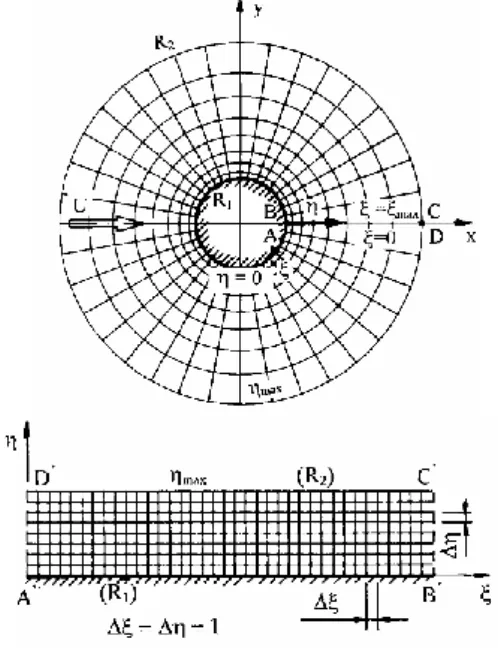
The physical and computational domains are shown in Fig. 1. The cylinder surface is represented by the dimensionless radius R1 and that of the far field, where potential flow is assumed, is denoted by R2. Dirichlet-type boundary conditions are used for the velocity components and Neumann-type boundary conditions is applied for pressure both on the cylinder surface and in the far field [14].
Figure 1. The physical and computational domains
In order to satisfy the boundary conditions accurately, the physical domain is mapped into a rectangular computational domain. Mapping functions are chosen so that the grid on the computational plane is equidistant and the mesh on physical domain is fine near the cylinder and coarse in the far field. An in-house code based on the finite difference method is used to solve the transformed governing equations with the boundary conditions [14]. The space derivatives are discretised using fourth-order accurate difference schemes except for the convective terms, where third-order modified
upwind difference scheme is applied [14]. The two components of the Navier-Stokes equations and the two structural equations are integrated explicitly and the pressure Poisson equation is solved using the successive over-relaxation method.
The computational method was extensively validated against the available experimental and numerical data for stationary cylinder and forced cylinder oscillation cases (see [14]). Results obtained using the current code also compare well with those available the literature for elastically supported cylinder [15].
In this study the number of grid points is fixed at 360×292, the computational domain is characterised by R2/R1=160 and the dimensionless time step is kept at 0.0005.
3. COMPUTATIONAL SETUP
In this study the effects of streamwise and transverse structural damping coefficients (ζx and ζy) on the flow around an elastically supported circular cylinder in 2DoF motions are investigated numerically at the mass ratio value of m*=10. The natural frequencies in the two directions are chosen to be identical fNx = fNy = fN therefore the reduced velocities are also equal, 𝑈𝑥∗= 𝑈𝑦∗= 𝑈∗. Furthermore, keeping fN at constant value, a linear relationship can be written between Re and U*, i.e.
Re=KU*, where K=fNd2/ν is the non-dimensional natural frequency. Assuming that the reduced natural frequency FN=1/U* is equal to the dimensionless vortex shedding frequency for a stationary cylinder St0 at Re0=180, the non-dimensional natural frequency can be computed as K=Re0 × St0=34.74 (here St0=0.192 is obtained from [16]). Using Re=34.74U*, Reynolds number and the reduced velocity values are varied within the ranges of Re=80–240 and U*=2.3–6.91, correspondingly.
The numerical simulations for undamped cylinder oscillations show that lock-in occurs between Re≅164–212 and U*≅4.72–6.1. The individual effects of ζx and ζy are investigated at Re=164, 175, 180 and 190, where relatively large oscillation amplitudes occur. The corresponding U*
values are calculated as U*=Re/34.74. The streamwise and transverse damping coefficients are varied between ζx=0–15 and ζy=0–0.3, respectively.
It was found that ζy has a greater impact than ζx, therefore additional computations are carried out at fixed transverse structural damping values of ζy=0.001, 0.04, 0.06 and 0.2 while the streamwise structural damping coefficient is set to zero (ζx=0) and Re is varied with U* using Re=34.74U*.
4. COMPUTATIONS FOR DIFFERENT REYNOLDS NUMBERS
Figure 2 shows the root-mean-square (rms) values of the transverse cylinder displacement y0rms against Reynolds number for ζx = ζy = 0. Two-branch
cylinder response was identified, which is consistent with the results available in the literature for low Reynolds numbers (see [12]). The initial branch occurs at Re<140 and U*<4.03 where low transverse cylinder displacement is observed [y0rms=O(10-2)].
This branch is associated with 2S vortex shedding mode ([17]; two single vortices are shed from the cylinder periodically). In the range of Re=164–212 and U*≅4.72–6.1 lock-in is observed, where y0rms
becomes large (y0rms≅0.41 at Re=164). C(2S) vortex structure is observed at the lower edge of the lock-in domain (either positive and negative vortices coalesce in the cylinder wake, see [17]). With increasing Re and U* in the synchronisation domain, y0rms decreases and at Re=178.8 a small jump is observed. This jump is associated with a switch in the vortex structure from C(2S) to 2S mode. The vortex contours at the two sides of the jump are shown in Fig. 3a and 3b.
Figure 2. The rms values of transverse cylinder displacement for ζx=ζy=0
(a) Re=178.7
(b) Re=178.8
Figure 3. Vortex contours at the two sides of the jump in y0rms at t=800
The effects of streamwise and transverse structural damping values are investigated at four different Reynolds numbers in the lock-in domain: at Re=164 and 175 where C(2S) vortex shedding mode is identified and at Re=180 and 190 where 2S mode is observed. Note that different reduced velocity
values belong to each Reynolds number (U*=Re/34.74), but only Re is used to identify the different computational cases here.
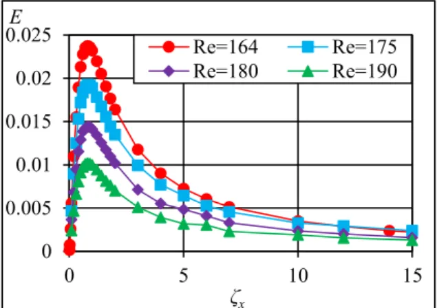
4.1. Effects of streamwise damping The effect of ζx is investigated first while the transverse damping is kept at zero (ζy=0). Figure 4 shows the mechanical energy transfer E between the oscillating cylinder and the surrounding fluid against ζx. It can be seen that E is positive in the entire ζx
domain, meaning that energy is transferred from the fluid to the cylinder. It can also be observed that by increasing ζx, the mechanical energy transfer first increases and reaches its maximum value at approximately ζx=1. The peak value decreases with Reynolds number but its location does not depend on Re. For damping coefficients over ζx>1 E decreases gradually. In Fig. 5 the rms values of drag CDrms are shown against ζx. The CDrms curves shift downwards with increasing Re. Overall, it is found that aside from the negligible increase in E, the streamwise structural damping coefficient does not have any significant effect.
Figure 4. Mechanical energy transfer against ζx at different Re for ζy=0
Figure 5. The rms values of drag against ζx at different Re for ζy=0
0 0.050.1 0.150.2 0.250.3 0.350.4 0.45
80 120 160 200 240
y0rms
Re
0 0.005 0.01 0.015 0.02 0.025
0 5 10 15
E
ζx
Re=164 Re=175
Re=180 Re=190
0.3 0.35 0.4 0.450.5 0.550.6 0.650.7 0.75
0 5 10 15
CDrms
ζx
Re=164 Re=175
Re=180 Re=190
4.2. Effects of transverse damping The effect of transverse structural damping is investigated by varying the coefficient ζy (ζx=0).
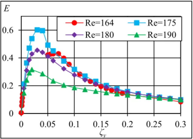
Figure 6 shows mechanical energy transfer E against ζy at four different Reynolds numbers. It can be seen in the figure that for the undamped vibration (ζx=ζy=0) E is approximately zero for all Re values investigated. At low transverse damping values E increases steeply with ζy and in three cases reaches its maximum value at ζy≅0.03. The transverse damping effect is much stronger than the streamwise:
for instance, at Re=175 the maximum value of the mechanical energy transfer obtained by varying ζy is Emax≅0.6, around 30 times larger than the result of Emax≅0.02 by varying ζx (see Fig. 4). As ζy is further increased, E decreases gradually. It can also be seen that the E curves belonging to increasing Reynolds numbers (except for Re=164) shift downwards and, as expected, using large damping (ζy>0.2) E is almost the same for all the investigated Re values.
The results for Re=164 show somewhat different behaviour. The maximum energy transfer values appear to be smaller than those computed for Re=175, although some computational points are not plotted in the range of ζy=0.006–0.04 due to irregular cylinder motion. One possible explanation is that the combination of (Re, U*)≅(164, 4.721) for undamped vibration is near the boundary that separates initial and lower branches, where the flow is chaotic.
Figure 6. Mechanical energy transfer ζy at different Re for ζx=0
The question arises which vibration component is responsible for high energy transfer. In Figs. 7 and 8 the time histories of 𝐶𝐿𝑦̇0 and 𝐶𝐷𝑥̇0 are shown.
Integrating these signals over a motion period T the mechanical energy transfer values originating from streamwise and transverse motions (E1 and E2) are obtained [see Eq. (3)]. It can be seen in Fig. 7 that the area under 𝐶𝐿𝑦̇0 over T where 𝐶𝐿𝑦̇0>0 (indicated by
‘+’ markers) is significantly larger than that where 𝐶𝐿𝑦̇0<0 (shown by ‘–’ markers), which leads to relatively large E2>0. On the other hand E1 is approximately zero because the areas under 𝐶𝐷𝑥̇0
over T where 𝐶𝐷𝑥̇0>0 and 𝐶𝐷𝑥̇0<0 are almost
identical (see in Fig. 8). For this reason the mechanical energy transfer (E=E1+E2) is influenced mainly by transverse cylinder motion.
+ + +
– – –
+ 0 –
0.05 0.1 0.15
0.3
570 572 574 576 578 580
CLy0 [ -]
t[ -]
.
Figure 7. Time history of 𝑪𝑳𝒚̇𝟎 for (ζx, ζy)=(0, 0.06) at Re=164
+ + +
– – – –
570 572 574 576 578 580
t[ -]
-8 -6 -4 -2 0 2 4 6 8
103 CDx0 [ -]
Figure 8. Time history of 𝑪𝑫𝒙̇𝟎 for (ζx, ζy)=(0, 0.06) at Re=164
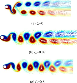
Figure 9 shows vortex structures at three different ζy values for Re=175. It is found that at Reynolds numbers where C(2S) mode is identified for undamped vibration (Re=164 and 175 in this study) C(2S) vortex shedding mode is observed below ζy=0.07 (see Fig. 9a and b). In the vicinity of ζy=0.07 the vortex structure changes from C(2S) to 2S mode which is shown in Fig. 9c. In contrast, vortex shedding mode does not change where 2S mode is observed originally at ζx=ζy=0 (Re=180 and 190 in this study).
In Figs. 10 and 11 the rms and time-mean (TM) values of drag coefficient CDrms and CDmean are plotted against ζy for different Re values. It can be seen that varying transverse damping from ζy=0 to 0.1 CDmean and CDrms diminish approximately by 25%
and 75%, respectively. Beyond ζy=0.1 CDmean and CDrms remain almost constant for all the Reynolds numbers investigated. No strong Re effect is found, as the curves fall close to each other.
0 0.2 0.4 0.6
0 0.05 0.1 0.15 0.2 0.25 0.3
E
ζy
Re=164 Re=175
Re=180 Re=190
(a) ζy=0
(b) ζy=0.07
(c) ζy=0.8
Figure 9. Vortex structures at different ζy values for Re=164 and ζx=0 at t=800
Figure 10. The time-mean values of drag against ζy at different Re for ζx=0
Figure 11. The rms values of drag against ζy at different Re for ζx=0
5. COMPUTATIONS FOR DIFFERENT TRANSVERSE DAMPING VALUES It was shown in Section 4 that ζy influences the flow much more strongly than ζx. For this reason systematic computations are carried out at different damping coefficients of ζy=0.001, 0.04, 0.06 and 0.2, while keeping ζx=0 and the natural frequency constant (Re=34.74U*). In these investigations the Reynolds number and the reduced velocity are varied (Re=80–240 and U*=2.3–6.91).
In Fig. 12 y0rms is shown against Re for different ζy values. It can be seen that the results for ζy=0.001 are very similar to those from undamped vibrations (ζx=ζy=0); the cylinder response shows two-branch behaviour and at the boundaries of the lock-in domain irregular cylinder motion is observed. In contrast, for ζy=0.04, 0.06 and 0.2 the chaotic flow regime at the lower and upper limit of the synchronisation domain completely disappears and y0rms increases to around Re=175 and beyond that decreases continuously. As expected, y0rms curves belonging to increasing ζy values shift to lower values in the lock-in domain.
Figure 12. The rms values of transverse cylinder displacement against Re at different ζy values for ζx=0
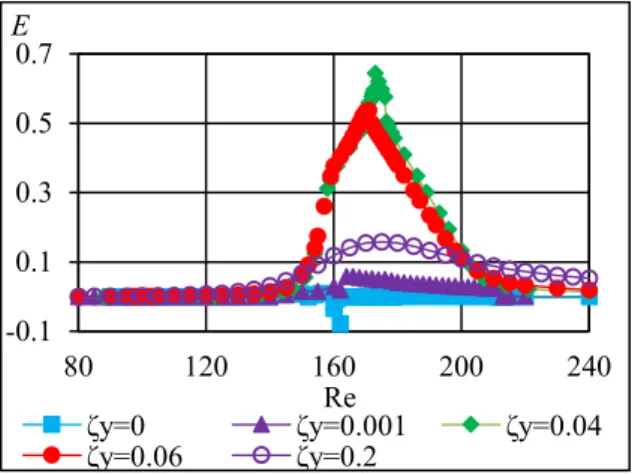
Figure 13 shows mechanical energy transfer against Re for different ζy values. It can be seen that for undamped vibration E is approximately zero. For ζy=0.001 E slightly increases but is still negligible.
The results show that large positive mechanical energy transfer values can be obtained in the domain of Re=160–180 for relatively small transverse damping (ζy=0.04 and 0.06). As was seen in Fig. 6, where ζy was varied independently, for large ζy
values E decreases, which is consistent with results in Fig. 13: for ζy=0.2 lower mechanical energy transfer occurs compared to the cases ζy=0.04 and 0.06.
In Figs. 14 and 15 CDmean and CDrms are shown for different transverse damping values. It is no surprise that for the smallest ζy value (here ζy=0.001) the results do not differ from those obtained for the 1.2
1.4 1.6 1.8 2 2.2
0 0.05 0.1 0.15 0.2 0.25 0.3
CDmean
ζy
Re=164 Re=175
Re=180 Re=190
0 0.2 0.4 0.6
0 0.05 0.1 0.15 0.2 0.25 0.3
CDrms
ζy
Re=164 Re=175
Re=180 Re=190
0 0.1 0.2 0.3 0.4 0.5
80 120 160 200 240
y0rms
ζy=0 ζy=0.001Re ζy=0.04
ζy=0.06 ζy=0.2
undamped case (similarly to y0rms shown in Fig. 12).
For larger but still small damping values (ζy=0.04 or 0.06) CDmean and CDrms curves belonging to different ζy shift downwards within the lock-in domain. For ζy=0.2, where the maximum transverse oscillation amplitude is about y0rms=0.05 (an almost stationary cylinder) neither CDmean nor CDrms show significant increases.
Figure 13. Mechanical energy transfer against Re at different ζy values for ζx=0
Figure 14. The time-mean values of drag against Re at different ζy for ζx=0
Figure 15. The rms values of drag against Re at different ζy values for ζx=0
5. CONCLUSIONS
In this study two-dimensional flow around an elastically supported circular cylinder in 2DoF motion is investigated at the mass ratio value of m*=10. The natural frequency of the cylinder is assumed to be constant, leading to a linear relationship between Reynolds number Re and reduced velocity U*, i.e. Re=KU* where K=34.74 is the non-dimensional natural frequency. The individual effects of streamwise and transverse structural damping coefficients (ζx and ζy) are investigated at Re=164 and 175, with C(2S) vortex shedding mode, and at Re=180 and 190, where 2S vortex structure is identified for undamped vibration.
The main findings are as follows:
Streamwise damping coefficient ζx slightly influences the mechanical energy transfer E;
Transverse damping coefficient ζy has a much stronger influence than ζx. Changes in ζy may result in large effects on E and the amplitude of cylinder vibration. The peak energy transfer Emax=0.6 obtained at Re=175 is almost 30 times larger than Emax=0.02 obtained by varying ζx at the same Re. The transverse vibration component is mainly responsible for the energy transfer. By increasing ζy over 0.02 E decreases gradually.
Transverse damping may affect vortex structure. Changes from C(2S) to 2S mode were found at ζy≅0.07 in Reynolds numbers where C(2S) mode was identified for undamped vibration, but 2S mode remained unchanged.
Drastic decreases occur in CDrms and CDmean
when transverse damping is changed from ζy=0 to 0.1, but values fall only gradually at larger ζy values.
Systematic computations are carried out for ζy=0.001, 0.04, 0.06 and 0.2 where Re and U* are varied between Re=80–240 and U*=2.3–6.91 using Re=34.74U*. The main findings:
The results for ζy=0.001 are similar to those for undamped vibration. Chaotic cylinder motion is observed at the boundaries of the lock-in regime and E approaches low values.
Using transverse damping values of ζy=0.04, 0.06 and 0.2 chaotic flow domain at the lower and upper edges of the synchronization domain completely disappear.
High mechanical energy transfer can be obtained for ζy=0.04 and 0.06.
ACKNOWLEDGEMENTS
The research was supported by the EFOP-3.6.1-16- 00011 “Younger and Renewing University – -0.1
0.1 0.3 0.5 0.7
80 120 160 200 240
E
ζy=0 ζy=0.001Re ζy=0.04
ζy=0.06 ζy=0.2
1.2 1.4 1.6 1.8 2 2.2
80 120 160 200 240
CDmean
ζy=0 ζy=0.001Re ζy=0.04
ζy=0.06 ζy=0.2
0 0.2 0.4 0.6
80 120 160 200 240
CDrms
ζy=0 ζy=0.001Re ζy=0.04
ζy=0.06 ζy=0.2
Innovative Knowledge City – institutional development of the University of Miskolc aiming at intelligent specialization” project implemented in the framework of the Széchenyi 2020 program. The realization of this project is supported by the European Union, co-financed by the European Social Fund.
REFERENCES
[1] Bernitsas, M.M., Raghavan, K. and Garcia, E.M.H., 2008, “VIVACE (Vortex Induced Vibration Aquatic Clean Energy): a new concept in generation of clean and renewable energy from fluid flow”, J Offshore Mech Arct, Vol. 130, pp. 1–15.
[2] Khalak, A., and Williamson, C.H.K., 1999,
“Motions, forces and mode transitions in vortex-induced vibrations at low mass- damping”, J Fluid Struct, Vol. 13, pp. 813–851.
[3] Feng, CC., 1968, “The measurement of vortex- induced effects in flow past stationary and oscillating circular and D-section cylinders”, Master thesis, University of British Columbia, Vancouver, B.C., Canada
[4] Klamo, J.T., Leonard, A., and Roshko, A., 2006, “The effect of damping on the amplitude and frequency response of a freely vibrating cylinder in cross-flow”, J Fluid Struct, Vol. 22, pp. 845–856.
[5] Bahmani, M.H., and Akbari, M.H., 2010,
“Effect of mass and damping ratios on VIV of a circular cylinder”, Ocean Eng, Vol. 37, pp.
511–519.
[6] Leontini, J.S., Thompson, M.C., and Hourigan, K., 2006, “The beginning of branching behavior of vortex-induced vibration during two-dimensional flow”, J Fluid Struct, Vol. 22, pp. 857–864.
[7] Moe, G. and Wu, Z.-J., 1990, “The lift force on a cylinder vibrating in a current”, J Offshore Mech Arct, Vol. 112, pp. 297–303.
[8] Sarpkaya, T., 1995, “Hydrodynamic damping, flow-induced oscillations, and biharmonic response”, J Offshore Mech Arct, Vol. 117, pp.
232–238.
[9] Dahl, J.M., Hover, F.S. and Triantafyllou, M.S., 2006, “Two-degree-of-freedom vortex- induced vibrations using a force assisted apparatus”, J Fluid Struct, Vol. 22, 807–818.
[10] Jauvtis, N., and Williamson, C.H.K., 2004,
“The effect of two degrees of freedom on vortex-induced vibration at low mass and damping”, J Fluid Mech, Vol. 509, pp. 23–62.
[11] Singh, S.P., and Mittal, S., 2005, “Vortex- induced oscillations at low Reynolds numbers:
hysteresis and vortex-shedding modes”, J Fluid Struct, Vol. 20, pp. 1085–1104.
[12] Prasanth, T.K., and Mittal, S., 2008, “Vortex- induced vibrations of a circular cylinder at low Reynolds numbers”, J Fluid Mech, Vol. 594, pp. 463–491.
[13] Willden, R.H.J., and Graham, J.M.R., 2006,
“Three distinct response regimes for transverse vortex-induced vibrations of circular cylinders at low Reynolds numbers”, J Fluid Struct, Vol.
22, pp. 885–895.
[14] Baranyi, L., 2008, “Numerical simulation of flow around an orbiting cylinder at different ellipticity values”, J Fluid Struct, Vol. 24, pp.
883–906.
[15] Dorogi, D., and Baranyi, L., 2017, “Elastically supported cylinder in two-degrees-of-freedom motion: a numerical study”, Proc. MultiScience - XXXI. microCAD International Multidisciplinary Scientific Conference, Section D1, Miskolc, Hungary, pp. 93–100, paper number D1_12
[16] Posdziech, P., and Grundmann, R., 2007, “A systematic approach to the numerical calculation of fundamental quantities of the two-dimensional flow over a circular cylinder”, J Fluid Struct, Vol. 23, pp. 479–499.
[17] Williamson, C.H.K. and Roshko, A., 1988,
“Vortex formation in the wake of an oscillating cylinder”, J Fluids Struct, Vol. 2, pp. 355–381.