UNCORRECTED
PROOF
Contents lists available at ScienceDirect
International Communications in Heat and Mass Transfer
journal homepage: www.elsevier.com
Cross-buoyancy mixed convection from a heated cylinder placed asymmetrically in a channel
Amit Dhiman
a, Rishabh Gupta
a, László Baranyi
b, ⁎aDepartment of Chemical Engineering, Indian Institute of Technology Roorkee, Roorkee 247 667, India
bDepartment of Fluid and Heat Engineering, Institute of Energy Engineering and Chemical Machinery, University of Miskolc, 3515 Miskolc-Egyetemváros, Hungary
A R T I C L E I N F O
Keywords:
Asymmetry Confined cylinder Gap ratio Mixed convection Wall confinement
A B S T R A C T
Mixed convection heat transfer from a heated circular cylinder asymmetrically placed in a horizontal channel was studied for incompressible Newtonian fluid. A systematic investigation using two-dimensional numerical simulation (Ansys Fluent) was performed for the following control parameters: Reynolds numberRe=50, 100, 150, Richardson number Ri=0, 1, 2, blockage ratioβ=0.2, 0.3, 0.4, gap ratioγ=0.25, 0.5, 1 and Prandtl number of airPr=0.7. Upon changing these parameters, steady and time periodic regimes were identified. The strongest influence on heat transfer (average Nusselt number) was identified when changing the Reynolds num- ber (a 94% increase between the minimum and maximumReinvestigated, with other parameters held constant), followed by Richardson number (+18%) and blockage ratio (+16%); the effect of asymmetric placement (γ) was almost negligible (+1%). The time-mean of the drag coefficient was most influenced by blockage ratio (a 150% increase), followed by Richardson number (+91%), gap ratio (+19%), andRe(+10%).
Nomenclature
CD total drag coefficient, = cp heat capacity, J/(kgK)
d diameter of cylinder, length scale, m
FD drag force per unit length of the cylinder, N/m g acceleration due to gravity, m/s2
Gr Grash of number, = H half channel height, m
h local heat transfer coefficient, W/(m2K) average heat transfer coefficient, W/(m2K) k thermal conductivity of fluid, W/(mK)
L dimensionless length of the computational domain in x-direction, =L∗/d
Ld dimensionless downstream length, =Ld∗/d Lu dimensionless upstream length, =Lu∗/d NuL local Nusselt number, =hd/k Nu average Nusselt number, =
P dimensionless pressure, =P∗/(ρU∞2)
Pr Prandtl number, =μcp/k Re Reynolds number, =ρdU∞/μ Ri Richardson number, =Gr/Re2 t dimensionless time, =t∗/(d/U∞) T temperature of fluid, K T0 fluid temperature at inlet, K Tw cylinder temperature, K
U∞ average inlet velocity, velocity scale, m/s
Vx,Vy dimensionlessxandyvelocity components, =Vx∗/U∞,
=Vy∗/U∞
x dimensionlessx-coordinate, =x∗/d y dimensionlessy-coordinate, =y∗/d β blockage ratio, =d/(2H)
βv volumetric expansion coefficient, 1/K γ gap ratio or eccentricity, =δ/(H−d/2) δ gap between lower channel wall and cylinder, m θ non-dimensional temperature, =
μ dynamic viscosity of fluid, Pas ρ fluid density, kg/m3
Superscript
⁎ Corresponding author.
Email addresses:amitdfch@iitr.ac.in (A. Dhiman); arambl@uni-miskolc.hu (L. Baranyi) https://doi.org/10.1016/j.icheatmasstransfer.2018.05.007
Available online xxx
UNCORRECTED
PROOF
* dimensional quantity
1. Introduction
The study of fluid dynamics and heat transfer characteristics around various bluff bodies in an enclosure has been given a great deal of atten- tion by researchers in recent times because of its pragmatic relevance.
While many studies are available on forced convection flow alone, in real life there is always a combination of free and forced convection.
In most situations, free convection is always present, though sometimes small, and this leads to heat transfer through mixed convection. This mixed convection has numerous real world applications such as heat ex- changers, transport of fluid in pipelines, cooling towers, etc. Although it is more difficult to analyse and study mixed convection as compared to forced convection alone, both forced convection and mixed convec- tion from an unconfined circular cylinder have been fairly widely stud- ied. In contrast, there are few studies available on mixed convection heat transfer from a cylinder in a confined channel, and to the best knowledge of the authors no results have been published on mixed con- vection from a confined heated cylinder placed asymmetrically. In this study, cross-buoyancy mixed convection is investigated for incompress- ible Newtonian fluid from a heated circular cylinder placed in a channel in symmetrical and asymmetrical positions.
2. Current status of literature
Following is a summary of previous studies related to the flow of fluids past and heat transfer from a circular cylinder placed at various positions in a confined two-dimensional (2-D) channel. It is presented in the following manner: studies on flow around and forces acting on a cylinder in a confined channel, forced convection studies for a symmet- rically and then an asymmetrically placed cylinder, and mixed convec- tion studies for a symmetrically placed cylinder.
Experimental and numerical research is now accessible in the lit- erature on the fluid flow in the symmetrical placement of a circular cylinder between the walls of a channel (confined domain) [1–8]. Like- wise, adequate research on three-dimensional effects in laminar flow around a circular cylinder in the channel can be found in [9–13]. On the other hand, Zovatto and Pedrizzetti [14] studied the effects of wall confinement (blockage ratioβ=b/(2H)) and the flow separation from the cylinder surface. It was reported that the transition from steady state flow to the vortex shedding regime was delayed for higher blockage ra- tios, where the walls are placed nearer to the cylinder, because of the stability provided by the confining walls to the wake that formed behind the cylinder. Thus, blockage ratio above a certain value led to inhibition of the vortex shedding phenomenon.
In [15–18] a heated circular cylinder is symmetrically placed (gap ratioγ=1) in a channel and forced convection (Richardson number Ri=0) is assumed. Progress in research on the forced convection can also be found for the asymmetrical placement of a circular cylinder in the confined domain [19–23]. Mettu et al. [19] explored flow around and forced convection from a circular cylinder placed asymmetrically in a planar channel for Reynolds numberReranging from 10 to 500, blockage ratioβfrom 0.1 to 0.4, gap ratioγfrom 0.125 to 1 and Prandtl numberPr=0.744. A critical Reynolds number that represents the shift from steady flow regime to unsteady periodic flow regime was deter- mined. Drag coefficient was found to increase with a decrease in the gap ratio. The oscillation amplitude of the lift signal was found to have an inverse relationship with blockage ratio.
Champmartin and Ambari [20] studied the effect of disturbances
rical configuration of a single cylinder moving in a horizontal confined channel with Dirichlet and Neumann boundary conditions was investi- gated numerically. The heat transfer was observed to increase with the blockage ratio when Dirichlet condition was used, while an inverse rela- tion was obtained for the Neumann condition. Investigating symmetri- cal versus asymmetrical confinement, Nirmalkar and Chhabra [21] stud- ied the momentum and heat transfer characteristics from the power-law fluid flow past a heated cylinder in asymmetric confinement forRerang- ing from 0.1 to 100,Prfrom 1 to 100,βfrom 0.2 to 0.4 andγfrom 0.25 to 1. They found that Nusselt number did not follow any trend with re- spect to the asymmetry in the placement of the cylinder. As the cylinder was placed away from the centre of the channel, there was an imbal- ance of force acting on the cylinder in the vertical direction because of both confining walls, with the wall closer to the cylinder exerting more repellent force than the wall further away from the cylinder, thus lead- ing to some positive value of lift coefficient. However, the drag coeffi- cient and Nusselt number were far more influenced by other parame- ters likeReandβthan byγ. In a recent investigation, Bijjam et al. [23]
studied the forced convection from an asymmetrically confined cylinder forRe=1–40,γ=0.375–1,β=0.2–0.5 andPr=1–50. They found that asymmetrical configuration reduces overall drag, and that the Nusselt number is higher for symmetric cylinder placement than for asymmetric placement.
In contrast, mixed convection (Ri≠0) effects around a symmetrically placed circular cylinder in a channel have not been paid the same at- tention. Few investigations can be found for a confined symmetrically placed circular cylinder [24–28]. Farouk and Güçeri [24] dealt with mixed convection (aiding buoyancy) from a confined circular cylinder in the steady state atβ=0.1667. Singh et al. [25] examined the mixed convection (aiding/opposing buoyancy) from a confined cylinder for Re=100,Pr=0.7 and Ri=−1 to 1 atβ=0.25. Vortex shedding is not observed for Ri>0.15. The average Nusselt number increases consid- erably with Ri. Gandikota et al. [26] explored mixed convection (aid- ing/opposing buoyancy) effects for a confined cylinder atRe=50–150, Pr=0.7 and Ri=−0.5 to 0.5 atβ=0.25. The critical Ri at which vor- tex shedding stops was determined and it was found to increase withRe.
The average Nusselt number increases at a higher rate beyond a critical Ri; however, the value of the average Nusselt number remains constant in the negative Ri range. Hu and Koochesfahani [27] studied experi- mentally the effects of Ri (0–1.04) on the flow around a heated cylinder in a vertical water channel atRe=135 in a reverse flow situation. At Ri<0.31 the drag coefficient was observed to be slightly smaller than for the unheated cylinder, whereas for Ri>0.31, the drag coefficient in- creases linearly with Ri. The average Nusselt number decreases almost linearly with increasing Ri. Guillén et al. [28] recently carried out an experimental study to explore the mixed convection (aiding/opposing buoyancy) effects around a symmetrically placed confined cylinder for Re=170,Pr=7 and Ri=−1 to 5 atβ=0.287. They determined how the flow patterns and vortex shedding are modified byβand Ri.
While some literature is available on the mixed convection from a symmetrically confined circular cylinder [24–28], for the topic of flow around and mixed convection heat transfer from an asymmetrically con- fined circular cylinder there is no literature available, to the best knowl- edge of the authors. Thus, this study aims to investigate laminar flow and heat transfer for an asymmetrically confined cylinder under the in- fluence of cross-buoyancy mixed convection.
3. Problem statement and numerical details
This study investigates the 2-D flow of Newtonian fluid around a cir- cular cylinder of diameterdplaced in a channel of height 2Hlocated
UNCORRECTED
PROOF
distanceLuare shown in Fig. 1. The gap ratioγis used to define the posi- tion of the cylinder inside the channel, withγ=1 representing the cylin- der at centre andγ=0 representing the cylinder touching the lower wall of the channel. The blockage ratioβ=d/(2H) is used to describe the confinement of the channel. An incompressible Newtonian fluid hav- ing a fixed temperature ofT0enters the channel with a fully developed velocity profile and exchanges heat when it comes in contact with the cylinder, the surface of which is kept at a slightly higher constant tem- peratureTwwith a temperature difference∆T≈2K. Because of low∆T, all thermo-physical properties (heat capacity, viscosity, thermal conduc- tivity, etc.) can be assumed to be the constant except density. Boussinesq approximation is used to overcome the effect of temperature on density, and viscous dissipation is neglected because of the low Reynolds num- ber values investigated.
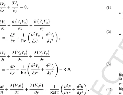
Considering the above assumptions, the continuity (Eq. 1), momen- tum (Eqs. (2) and (3)) and energy (Eq. 4) equations can be written in non-dimensional form as
(1)
(2)
(3)
(4) whereVx,Vyare thexandycomponents of velocity, respectively, which are made dimensionless byU∞, andPandθare the non-dimensional pressure and temperature, respectively. The definitions of Richardson Ri, PrandtlPrand ReynoldsRenumbers can be found in the Nomencla- ture.
The following boundary conditions (in non-dimensional form) are used:
• At the inlet plane (x=0): a fully developed velocity profile is as- sumed,
• At the channel walls: no-slip condition for velocity and adiabatic con- dition for temperature are used,
• On the cylinder: no-slip condition for flow and uniform wall temper- ature condition for temperature are used,
• At the outlet plane (x=40): the outflow setting in Ansys Fluent is used, which is a homogeneous Neumann condition for all dependent variables [8,23],
The meshing of the whole computational domain is performed us- ing Ansys Workbench. Fine meshing (minimum dimensionless grid size of 0.01) was chosen near the cylinder and near the adiabatic walls be- cause variations in the velocity and temperature are expected to be higher in these areas; for the rest of the domain a relatively coarse mesh is used. The momentum and energy equations along with the bound- ary conditions are solved using Ansys Fluent. The Gauss-Siedel itera- tive method is used to solve the algebraic equations. The pressure-based 2-D planar solver with SIMPLE algorithm is used. A second order up- wind scheme is used for the convective terms, whereas a central dif- ference scheme is used for the diffusive terms in the momentum and energy eqs. A fully developed velocity profile is inserted in Ansys Flu
Fig. 1.Schematic of the flow situation.
UNCORRECTED
PROOF
ent with the help of user-defined functions. The absolute convergence criteria for Eqs. (1) to (4) are set to 10−15.
4. Selection of numerical parameters
The choice of numerical parameters is crucial in determining the ac- curacy as well as the reliability of the solution. Thus, the choice of grid size, domain and time step are very important parameters to obtain ac- curate results with minimum usage of computational power. The do- main is given by the channel height 2H, the upstream lengthLu, the downstream lengthLdmeasured from the centre of the cylinder (see Fig. 1). The domain independence test is carried out at the minimum Revalue investigated because the momentum boundary layer is thick at lowRe, while the grid independence test is done at the maximum Reinvestigated, as at increasingRethe momentum boundary layer be- comes thinner. As the cylinder is placed asymmetrically inside the chan- nel, computations were carried out on the full computational domain even for steady flow.
Non-uniform grids (with minimum dimensionless grid sizes of 0.01 and 0.006 and with fine meshing in the no-slip zones) are chosen to obtain the optimum grid size. Results for time-mean of drag coefficient CD(hereafter drag coefficient or simplyCD) and average cylinder Nus- selt numberNu(which is the surface average of the local Nusselt num- ber NuL) at the highestReand the extreme value of all other variables in study are presented in Table 1. Based on these estimates, grid G1
Table 1
Variation ofCDandNuwith grid for Ri=0 and 2,Re=150,Pr=1,β=0.4,γ=1.
Grid No. of cells Minimum grid size CD Nu
Ri=0
G1 41,616 0.01 3.7059 9.5006
G2 68,240 0.006 3.6968 9.4773
% relative variation 0.24 0.25
Ri=2
G1 41,616 0.01 3.8244 9.6604
G2 68,240 0.006 3.8178 9.647
% relative variation 0.17 0.14
with minimum dimensionless grid size of 0.01 is chosen as the optimum grid size for further study, as not much variation in results occurs be- tween grids G1 and G2.
To fix the computational domain, the dimensionless upstream and downstream lengths were varied from 15 to 20 and from 40 to 45, re- spectively, for the extreme values of the parameters, i.e. atRe=50, 150, Ri=2,β=0.2 andγ=0.25, 1. The variations in the values ofCDand Nufor different cases are shown in Tables 2 and 3. It is clear that there is very little variation when the dimensionless upstream length is in- creased from 15 to 20 but the computational time required in obtaining these results increases significantly (e.g., 3 to 4days increase in the com- putational time). Hence,Lu=15 was chosen as the upstream length for the rest of the study, as it seems to give a proper balance between the ac- curacy and the computational cost. Similarly, the variation inCDandNu is reported by varying the dimensionless downstream length from 40 to 45. As there is not much variation in the results,Ld=40 was chosen as the downstream length. The entire domain independence test was done taking grid G1 with the minimum dimensionless grid size of 0.01. These distances are also consistent with the literature [5–8,17,19,21,23].
As the governing equations involved in the study are time-depen- dent, an acceptable value of dimensionless time step∆thas to be chosen to solve these equations. As in all the other tests, the values ofCDand Nu are compared at the different time steps to find the optimum balance between accuracy and computational time. From the results obtained (Table 4),∆t=0.01 seems to be the optimal choice for this study.
5. Results and discussion
In the current investigation, results are given for the following para- meter domains: Reynolds number Re=50, 100, 150, Richardson num- ber Ri=0, 1, 2, blockage ratioβ=0.2, 0.3, 0.4, gap ratioγ=0.25, 0.5, 1 and Prandtl number of air Pr=0.7. The values of gap ratio and blockage ratio are chosen based on [21]. The present results (CDand Nu) are compared with those in [8] at variousRevalues (50, 100, 150)
Table 2
Effect of upstream distanceLuonCDand Nu for Ri=2, Re=50 and 150, Pr=1.
β,γ Lu=15 Lu=20 % variation inCD % variation inNu
CD Nu CD Nu
Re=50
β=0.2,γ=1 3.2556 5.1121 3.2555 5.1117 0 0
β=0.4,γ=1 5.5119 5.6689 5.5119 5.6689 0 0
β=0.4,γ=0.25 6.8476 4.9607 6.8448 4.9613 0.04 0.01
Re=150
β=0.2,γ=1 2.863 9.1958 2.8625 9.1949 0.02 0.01
β=0.4,γ=1 3.8244 9.6604 3.8244 9.6604 0 0
β=0.4,γ=0.25 5.0697 9.1489 5.0684 9.1491 0.02 0
Table 3
Effect of downstream distanceLdonCDandNufor Ri=2,Re=50 and 150,Pr=1.
β,γ Ld=40 Ld=45 % variation inCD % variation inNu
CD Nu CD Nu
Re=50
β=0.2,γ=1 3.2556 5.1121 3.2556 5.1121 0 0
β=0.4,γ=1 5.5119 5.6689 5.5119 5.6689 0 0
β=0.4,γ=0.25 6.8476 4.9607 6.8448 4.9613 0.04 0.01
Re=150
β=0.2,γ=1 2.863 9.1958 2.8629 9.1958 0 0
β=0.4,γ=1 3.8244 9.6604 3.8244 9.6604 0 0
UNCORRECTED
PROOF
Table 4
Effect of time step∆tonCDandNufor Ri=0 and 2,Re=150,Pr=1.
β,γ ∆t=0.01 ∆t=0.005 % variation inCD % variation inNu
CD Nu CD Nu
Ri=0
β=0.2,γ=1 2.7699 8.9349 2.7699 8.9351 Negligible
β=0.4,γ=1 3.7059 9.5006 3.7056 9.5006
β=0.4,γ=0.25 3.3913 8.1831 3.3913 8.1831
Ri=2
β=0.2,γ=1 2.863 9.1958 2.8629 9.1957 Negligible
β=0.4,γ=1 3.8244 9.6604 3.8244 9.6603
β=0.4,γ=0.25 5.0697 9.1489 5.0697 9.1489
and blockage ratio of 0.25 for the limiting case ofγ=1 in Newtonian fluids. Table 5 clearly shows that there are no significant differences be- tween the present results and the results from [8].
5.1. Identification of steady and time periodic regimes
Table 6 shows the various flow regimes over the range of conditions in this study. Although this is not the main objective of the study, it is necessary to understand how the flow regimes change on changing var- ious parameters. It is clear (from Table 6) that the farther the cylinder is from the centre of the horizontal channel (i.e. the greater the blockage ratio is), the longer the steady state continues to exist. At the lowest gap ratio of 0.25, only steady states were found, irrespective of the investi- gated values of Re, Ri andβ.Due to the asymmetric positioning of the cylinder inside the planar channel, the vortex shedding phenomenon is delayed because of the reduction in interaction between the two vor- tices caused by proximity to the wall. A similar effect is seen for block- age ratio; for instance, forγ=1 and the highest blockage ratioβ=0.4, the flow was found to be steady forRe=50 irrespective of the value of Ri, while at reduced blockage ofβ=0.2, the flow is unsteady periodic for Ri=0 and 1.
5.2. Streamlines and isothermal patterns
Fig. 2 displays the instantaneous streamlines at the extreme settings ofRe=150 andβ=0.4 applied in the current investigation, for differ- ent Ri andγvalues. At low Re the fluid flow tends to remain attached to the cylinder but finally flow separates from the cylinder as we in- crease the Re, leading to the formation of separated flow regions in the wake of the cylinder. Also, the flow separation significantly depends upon the value of theγ. For the symmetric case (γ=1), the separation of flow is represented by the formation of the two asymmetric alternate vortices. On the other hand, in the case of asymmetrical placement of the cylinder (γ≠1), the flow separation occurs in the lower half of the computational domain and the asymmetric vortices are formed because of the smaller gap between the cylinder and the lower channel wall as compared with the gap between the cylinder and the upper channel wall. Moreover, the vortices formed are smaller compared to the sym- metrical case because of the proximity of the confining channel walls (or blockage effect). Similarly, as the blockage ratio increases, i.e. the walls become more confined, wall confinement tends to suppress wake formation and hence, shorter wakes tend to form in such cases. A rise in downstream streamlines (or an asymmetry in the flow field) and a far downstream wake can also be observed because of the effect of the cross-buoyancy mixed convection (Ri≠0). This asymmetry in the flow field increases with Ri because higher Ri values strengthen the cross-
Table 5
Validation of present results (CDandNu) with [8] at Ri=0 andβ=0.25.
Re Present study Ref. [8] % variation inCD % variation inNu
CD Nu CD Nu
50 3.4923 4.5324 3.4953 4.5313 0.09 0.02
100 2.9145 6.329 2.9143 6.3243 0 0.07
150 2.8025 7.806 2.8023 7.8032 0 0.04
Table 6
Flow regimes encountered at various conditions (SS - steady state flow, US–unsteady state flow).
Ri β=0.2
Re β=0.3
Re β=0.4
Re γ
50 100 150 50 100 150 50 100 150
0 SS SS SS SS SS SS SS SS SS 0.25
1 SS SS SS SS SS SS SS SS SS
2 SS SS SS SS SS SS SS SS SS
0 SS US US SS US US SS SS US 0.5
1 SS US US SS US US SS SS US
2 SS US US SS SS SS SS SS US
0 US US US SS US US SS US US 1
1 US US US SS US US SS US US
2 SS US US SS US US SS US US
UNCORRECTED
PROOF
Fig. 2.Instantaneous streamlines atRe=150 andβ=0.4 for different Ri andγvalues.
buoyancy effect. However, the asymmetry in the flow field decreases with increasingγand/orβ.
In addition to providing information about the overall heat trans- fer, isotherm contours also help in visualising the variation in tempera- ture at different parts of the domain, described as hot and cold regions, which can be helpful in the making of various items like food materi- als and others that may be temperature sensitive. Accumulation of the isotherms just upstream of the cylinder (near the front stagnation point) can be observed from isotherms (Fig. 3), indicating higher local heat transfer (i.e. local values of Nusselt number) at that area. This crowd- ing of the isotherms seems to increase with an increase inRe, which explains the increase in Nusselt number withRe(Section 5.3). Simi- lar to the flow field, more asymmetry in isotherms can be seen in the thermal patterns at higher Ri. This can be attributed to the fact that at high values of Ri, thermal buoyancy effects are higher. These effects are much more pronounced when vortex shedding occurs. The asymmetry in isotherms decreases withγand/orβ.
5.3. Drag coefficient and Nusselt number
Variation of the time-mean or overall drag coefficientCDwithRe, Ri,βandγis analysed and plotted in Fig. 4 for steady as well as peri- odic regimes. The overall drag coefficient always decreases withReat fixed values of other parameters investigated. The drag coefficient fol- lows a direct increasing relationship with Ri for givenReandβ. The maximum percentage of increase in the value ofCDof about 91% (at Ri=2 with respect to Ri=0, i.e. (CD,Ri=2-CD,Ri=0)/CD,Ri=0×100) is seen at the low blockage ratioβ=0.2,γ=0.25 and at the highestRe=150 investigated. For the blockage ratio, it is clear from Fig. 4 that com- paringβ=0.2 with 0.4, the drag coefficient also increases for all the values of Ri andRe. As the proximity to the lower channel wall in- creases, the obstruction to the flow grows, resulting in a steeper veloc- ity gradient and thus higher drag force on the cylinder. This effect is
more significant at lowRebecause of the thicker boundary layer and higher viscous forces acting on the cylinder. There is not much variation in the drag coefficient with the gap ratio at lowRe, as also reported by Mettu et al. [19], but higher values ofReare also involved here; in most of these cases, the higher the gap ratio, the smaller the drag coefficient.
However, this is not true for all cases, for instance when the cylinder is placed symmetrically at the centre of the channel, much less variation is seen, especially for small blockage ratios.
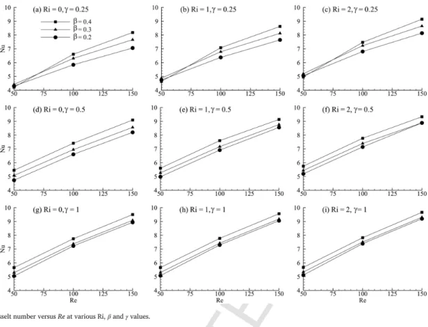
The average Nusselt number is calculated to estimate the rate of heat transfer from the cylinder to the ambient fluid. It seems to increase steadily with the value ofRewhen all other parameters are kept con- stant, as can be seen in Fig. 5. This can be attributed to the higher chance for vortex shedding, which increases the heat transfer. More- over, the thermal boundary layer keeps becoming thinner withRe, thus increasing the heat transfer rate. The maximum heat transfer change is found to be around 94% comparingRe=150 (β=0.4,γ=0.25, Ri=0) withRe=50 (β=0.4,γ=0.25, Ri=0).
The average Nusselt number also increases with Ri. Basically, Ri is the representation of free convection (due to buoyancy) relative to the forced convection. As Ri is increased, buoyancy forces responsible for the movement of the fluid due to mixed convection increase and thus the heat transfer rate also increases. The maximum heat transfer change is found to be around 18% at Ri=2 (Re=50,β=0.2,γ=0.25) with respect to Ri=0 (Re=50,β=0.2,γ=0.25).
As can be seen in Fig. 5, the average Nusselt number increases with the blockage ratio when all other parameters are kept constant. This is because as the blockage ratio is increased and the confining walls are set closer to the cylinder, a steeper temperature gradient occurs, leading to an increased heat transfer rate. Another result is when the cylinder is placed in the centre of the channel (γ=1), at the highest value of blockage ratio (β=0.4) investigated the variation in the Nus- selt number seems to be somewhat less significant than for asymmetric cylinder placement. The maximum heat transfer change is found to be
UNCORRECTED
PROOF
Fig. 3.Instantaneous isotherm contours atRe=150 andβ=0.4 for different Ri andγvalues.
Fig. 4.CDversusReat various Ri,βandγvalues.
around 16% at β=0.4 (Re=150, γ=0.25, Ri=0) with respect to β=0.2 (Re=150,γ=0.25, Ri=0). Asymmetric placement of the cylin- der in the channel has an adverse impact on the heat transfer rate.
Due to the asymmetric placement of the cylinder, the fluid flow can be
divided into two regions. While the fluid flowing below the cylinder near the bottom wall increases the local rate of heat transfer in the lower region, this is mostly offset by the poor circulation in the upper region of the flow, which overall decreases the average heat transfer
UNCORRECTED
PROOF
Fig. 5.Average Nusselt number versusReat various Ri,βandγvalues.
rate and thus the average Nusselt number (although not significantly).
The maximum heat transfer change is found to be only around 1%
at γ=0.25 (Re=50, β=0.2, Ri=2) with respect to γ=1 (Re=50, β=0.2, Ri=2).
Further comments can be made on the ratio of drag coefficient and average Nusselt number. Since the drag coefficient is a decreasing func- tion of theRe, while Nusselt number is an increasing function, it is ob- served that the ratio of both of these quantities decreases withRe. Both the drag coefficient and Nusselt number increase with Ri, and the ra- tio of these also increases, which shows that the drag increases with Ri at a slightly faster rate than Nusselt number does. This implies that heat transfer can be increased with Ri, but at the expense of higher drag forces on the cylinder. Increasing the blockage ratio tends to increase drag forces on the cylinder more than it increases heat transfer. More- over, when the cylinder is placed at the centre of the channel, it can be seen that there is not much change in the values of the ratio of drag to Nusselt number at various Ri, which means that the drag coefficient and the Nusselt number increase at roughly the same rate. However, when the cylinder is moved away from the centre of the channel the ratio increases, indicating that asymmetrical cylinder placement affects drag forces more strongly than it influences heat transfer.
6. Concluding remarks
The present study deals with the two-dimensional flow and heat transfer of an incompressible constant-property Newtonian fluid in a horizontal plane channel with a circular cylinder placed in a symmetric or asymmetric position. The aim here is to investigate the cross-buoy- ancy mixed convection from a confined asymmetric cylinder. We car- ried out domain-, grid- and time-step-independence studies. Steady and time periodic regimes were identified by changing various parameters.
The drag coefficient is found to be more strongly influenced by the Reynolds number, Richardson number and blockage ratio than by the gap ratio. Similarly, the average Nusselt number increases with each
parameter with the exception of the gap ratio, where the heat transfer rate decreases due to proximity of the cylinder to the wall. Moreover, the asymmetric placement of the cylinder increases the drag forces act- ing on the cylinder at a higher rate as compared to the increase in the heat transfer. The maximum heat transfer change is found to be around 94% atRe=150 (β=0.4,γ=0.25, Ri=0) with respect toRe=50 at the same parameters. Computations for higher Ri numbers and reduced γare planned for future work.
Acknowledgements
The third author gratefully acknowledges the support of the Eu- ropean Union and the Hungarian State, co-financed by the European Regional Development Fund in the framework of the GINOP-2.3.4-15-2016-00004 project, aimed to promote the cooperation between the higher education and the industry. The research was also supported by the EFOP-3.6.1-16-00011 “Younger and Renewing Uni- versity–Innovative Knowledge City–institutional development of the University of Miskolc aiming at intelligent specialisation”project imple- mented in the framework of the Széchenyi 2020 program. The realiza- tion of these two projects is supported by the European Union, co-fi- nanced by the European Social Fund.
References
[1] J.H. Chen, W.G. Pritchard, S.J. Tavener, Bifurcation of flow past a cylinder be- tween parallel plates, J. Fluid Mech. 284 (1995) 23–41.
[2] P. Anagnostopoulos, G. Illiadis, S. Richardson, Numerical study of the blockage ef- fect on viscous flow past a circular cylinder, Int. J. Numer. Meth. Fl. 22 (1996) 1061–1074.
[3] M. Sahin, R.G. Owens, A numerical investigation of wall effects up to high block- age ratios on two-dimensional flow past a confined circular cylinder, Phys. Fluids 16 (2004) 1305–1320.
[4] A.B. Richou, A. Ambari, J.K. Naciri, Drag force on a circular cylinder midway be- tween two parallel plates at very low Reynolds numbers, part 1: Poiseuille flow
UNCORRECTED
PROOF
[5] R.P. Bharti, R.P. Chhabra, V. Eswaran, Two-dimensional steady Poiseuille flow of power-law fluids across a circular cylinder in a plane confined channel: wall effects and drag coefficients, Ind. Eng. Chem. Res. 46 (2007) 3820–3840.
[6] M.K. Rao, A.K. Sahu, R.P. Chhabra, Effect of confinement on power-law fluid flow past a circular cylinder, Polym. Eng. Sci. 51 (2011) 2044–2065.
[7] A. Nejat, V. Abdollahi, K. Vahidkhah, Lattice Boltzmann simulation of non-New- tonian flows past confined cylinders, J. Non-Newton. Fluid. 166 (2011) 689–697.
[8] S. Bijjam, A.K. Dhiman, CFD analysis of two-dimensional non-Newtonian power-law flow across a circular cylinder confined in a channel, Chem. Eng. Com- mun. 199 (2012) 767–785.
[9] R.M.C. So, Y. Liu, Z.X. Cui, C.H. Zhang, X.Q. Wang, Three-dimensional wake ef- fects on flow-induced forces, J. Fluid. Struct. 20 (2005) 373–402.
[10] Y. Liu, Bifurcation phenomenon in the wake of a 3-D cylinder, Comput. Fluids 37 (2008) 724–732.
[11] S. Camarri, F. Giannetti, Effect of confinement on three-dimensional stability in the wake of a circular cylinder, J. Fluid Mech. 642 (2010) 477–487.
[12] N. Kanaris, D. Grigoriadis, S. Kassinos, Three dimensional flow around a circular cylinder confined in a plane channel, Phys. Fluids 23 (064106) (2011) 1–14.
[13] V.M. Ribeiro, P.M. Coelho, F.T. Pinho, M.A. Alves, Three-dimensional effects in laminar flow past a confined cylinder, Chem. Eng. Sci. 84 (2012) 155–159.
[14] L. Zovatto, G. Pedrizzetti, Flow about a circular cylinder between parallel walls, J.
Fluid Mech. 440 (2001) 1–25.
[15] W.A. Khan, J.R. Culham, M.M. Yovanovich, Fluid flow and heat transfer from a cylinder between parallel planes, J. Thermophys. Heat Tr. 18 (2004) 395–403.
[16] W.A. Khan, J.R. Culham, M.M. Yovanovich, Fluid flow and heat transfer in power-law fluids across circular cylinders: analytical study, J. Heat Transf.
128 (2006) 870–878.
[17] R.P. Bharti, R.P. Chhabra, V. Eswaran, Effect of blockage on heat transfer from a cylinder to power law liquids, Chem. Eng. Sci. 62 (2007) 4729–4741.
[18] W.K. Hussam, M.C. Thompson, G.J. Sheard, Dynamics and heat transfer in a quasi-two-dimensional MHD flow past a circular cylinder in a duct at high Hart- mann number, Int. J. Heat Mass Transf. 54 (2011) 1091–1100.
[19] S. Mettu, N. Verma, R.P. Chhabra, Momentum and heat transfer from an asymmet- rically confined circular cylinder in a plane channel, Heat Mass Transf. 42 (2006) 1037–1048.
[20] S. Champmartin, A. Ambari, Consequences of an asymmetrical confinement in the transfer phenomena for a cylinder at low Reynolds numbers, Chem. Eng. Sci.
63 (2008) 3171–3180.
[21] N. Nirmalkar, R.P. Chhabra, Forced convection in power-law fluids from an asym- metrically confined heated circular cylinder, Int. J. Heat Mass Transf. 55 (2011) 235–250.
[22] W.K. Hussam, G.J. Sheard, Heat transfer in a high Hartmann number MHD duct flow with a circular cylinder placed near the heated side-wall, Int. J. Heat Mass Transf. 67 (2013) 944–954.
[23] S. Bijjam, A. Dhiman, V. Gautam, Laminar momentum and heat transfer phenom- ena of power-law dilatant fluids around an asymmetrically confined cylinder, Int.
J. Therm. Sci. 88 (2015) 110–127.
[24] B. Farouk, S. Güçeri, Natural and mixed convection heat transfer around a horizon- tal cylinder within confining walls, Numer. Heat Tr. A-Appl. 5 (1982) 329–341.
[25] S. Singh, G. Biswas, A. Mukhopadhyay, Effect of thermal buoyancy on the flow through a vertical channel with a built-in circular cylinder, Numer. Heat Tr.
A-Appl. 34 (1998) 769–789.
[26] G. Gandikota, S. Amiroudine, D. Chatterjee, G. Biswas, The effect of aiding/oppos- ing buoyancy on two-dimensional laminar flow across a circular cylinder, Numer.
Heat Tr. A-Appl. 58 (2010) 385–402.
[27] H. Hu, M.M. Koochesfahani, Thermal effects on the wake of a heated circular cylinder operating in the mixed convection regime, J. Fluid Mech. 685 (2011) 235–270.
[28] I. Guillén, C. Treviño, L. Martínez-Suástegui, Unsteady laminar mixed convection heat transfer from a horizontal isothermal cylinder in contra-flow: buoyancy and wall proximity effects on the flow response and wake structure, Exp. Thermal Fluid Sci. 52 (2014) 30–46.