Real-time Two-dimensional Measurement of Angular Dispersion of Broadband Laser Beams
A. Börzsönyi
a,b, L. Mangin-Thro
a,c, G. Cheriaux
d, K. Osvay
b,*a CE Optics Kft., Kígyó u. 4, H-6720 Szeged, Hungary
b Department of Optics and Quantum Electronics, University of Szeged, P.O. Box 406, H-6701 Szeged, Hungary
c École Nationale Supérieure de Physique de Strasbourg, Univ. of Strasbourg, Pôle API - Bd Sébastien Brant - F 67400 Strasbourg, France
d Laboratoire d’Optique Appliquée, ENSTA, École Polytechnique CNRS Palaiseau Cedex, F-91761, France
* e-mail: osvay@physx.u-szeged.hu
Abstract. In present paper, we demonstrate a simple technique for angular dispersion measurement, which allows two-dimensional detection in one shot and can be used in real-time acquisition. These make our method especially suitable for CPA compressor alignment.
Experimental accuracy found to be close to common 1D techniques.
Keywords: angular dispersion, compressor alignment, CPA lasers
PACS: 42.60.Jf Beam characteristics: profile, intensity, and power; spatial pattern formation
INTRODUCTION
Chirped pulse amplification (CPA) lasers require complete and distortion-free reconstruction of the pulses on the target both temporally and spatially. Misaligned stretcher-compressor of the CPA laser [1,2] introduces angular dispersion, which is responsible for most of the spatiotemporal deformations of ultrashort pulses. Most of the measurement techniques [1,3-5] developed so far are able to determine angular dispersion along one axis, therefore beam rotation and at least two subsequent measurements required for complete characterization. In this paper, we introduce a simple and fast method for detection of single-shot measurement of angular dispersion of laser beams of broadband sources.
Two different interpretations of angular dispersion are known in the practice of ultrashort lasers. One is defined by the angle dependence of propagation direction of spectral components [1], while the other is based on the angle between different phase fronts of different wavelengths [2]. These quantities are equal in plane wave approximation, but they behave differently during pulse propagation in the case of Gaussian beams [3].
A few different techniques have been developed so far for the detection either one of angular dispersions [4, 5], but since they are limited to measure along one spatial dimension only, beam rotation and at least two subsequent measurements required for complete beam profile characterization. If a laser beam suffers from angular dispersion, its spectral components propagate into different directions. Hence, in the
focal plane of an achromatic optical element the focal spot will be enlarged and distorted when compared to an angular dispersion free beam of the same size. The shape of the intensity distribution will be uniquely characteristic to spectral angular deviation. In the laboratory practice there are two major issues affecting the measurement. First, one has to distinguish the chromatic distortion of the focal spot from the blur of the image due to other type of optical aberrations. Second, the elongated focal spot has to be spectrally calibrated. Both problems can be solved if the broadband beam is spectrally modulated in a known manner.
PRINCIPLES OF THE TWO-DIMENSIONAL DETECTION TECHNIQUE
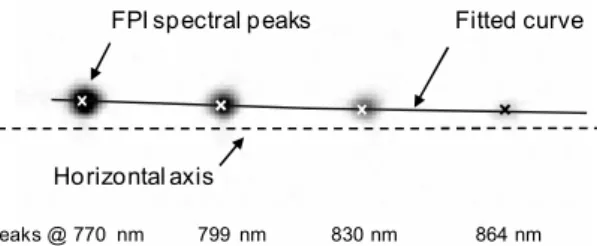
In present paper, we introduce a novel method for single-shot, two-dimensional measurement of propagation direction angular dispersion of broadband light sources, e.g. ultrashort laser beams. First, the beam is spectrally filtered in order to create well separated peaks in the spectrum. Since these components are still overlapping spatially, we use an achromatic lens to image them onto a CCD chip. In this way, the spectrally separated components of an angularly dispersed beam will appear as dissociated spots on the chip according to the orientation of the angular dispersion.
Sample with angular dispersion
Fabry-Perot Interferometer
Achromatic lens f = 500 mm
CCD
Broadband beam
CCD camera
FIGURE 1. Schematic layout of the technique.
The schematic diagram of our experiment is shown on Fig. 1. The set-up consisted of a Fabry-Perot Interferometer for spectral separation of the components of the broadband beam, and an achromatic lens with a focal lens of 500 mm, which focused these components onto the chip of a CCD camera. A typical recorded image can be seen on Fig. 2. Angular dispersion was introduced by regular prisms of different apex angles and materials. The measured values of angular dispersion were in great agreement with the calculations from prism data. We found that the accuracy and repeatability are better than 0.25 µrad/nm, which is very close to the precision of the most accurate methods.
Fitted curve
Horizontal axis
Peaks @ 770 nm 799 nm 830 nm 864 nm
FPI spectral peaks
FIGURE 2. Sample image of separated spots.
EXPERIMENTAL DEMONSTRATION
The angular dispersion of the laser beam of a regular CPA system has been measured during the alignment process of the compressor to demonstrate the efficiency of the 2D method. The experimental set-up is shown on Fig. 3. The amplified, but uncompressed pulses were going through the grating compressor. After the compressor, the pulses were directed towards to the 2D angular dispersion detection stage. Since the angular dispersion was not enough to separate the spectral peaks, a prism was inserted to have a constant bias in the angular dispersion.
Control Spectrograph
CCD
Ac. Lens
f = 500 mm
ND filter set
Iris1 Uncompressed pulses M1
after amplification Roof mirror
Grating 1
Grating 2
BS Iris2FPI Prism
Compressor
FIGURE 3. Experimental setup for characterizing the misalignment of a CPA compressor.
After subtracting the effect of the prism, the measured angular dispersion due to the compressor misalignment is shown on Figure 4. In the first series of measurements ((i) series, ▲ marks), the incident beam has been misaligned by tilting mirror M1. In the next step, Grating 1 has been rotated horizontally ((ii) series, marks). This rotation changed the angular dispersion by 0.7 µrad/nm per every arc minute of misalignment.
-5 0
5 10
15
20 -0.5 0
0.5 1 50 1.5
55 60 65 70 75
Tilt [deg]
-30
30 60
90
Angulardispersion[µrad/nm]
15 20 10 0 5
-5 0
-5 5 10 15 20
(i) (ii)
(iii)
FIGURE 4. A 3D plot of the total measured angular dispersion versus the misalignment axes. Projected arrows are showing the directions of measurement series.
With the horizontal angle misaligned as much as possible, the vertical direction of the incoming beam was varied again ((iii) series, marks). We experienced a jump in angular dispersion values, where the beam crossed the roof mirror joint; but an overall slope of 14.3 µrad/nm for every degree of tilt. The effect of vertical tilting of Grating 2 has been also investigated. We found a similar linear dependence with a slope of 50.4 µrad/nm per degree of tilt.
SUMMARY
In summary, we have developed a simple method for high accuracy two- dimensional measurement of angular dispersion along a laser beam. This method offers a very fast online diagnostic tool for the alignment of the stretcher-compressor system of CPA lasers.
ACKNOKLEDGEMENTS
This work was jointly supported by the Hungarian Scientific Research Found (OTKA) under grant No K75149, and by National Office for Research and Technology (NKTH) under grant no. Baross TECH-07-2008-0050. Financial support from the EU and co-funded by the European Social Fund through the grants no.
”TÁMOP-4.2.1/B-09/1/KONV-2010-0005” and ”TÁMOP 4.2.2/B-10/1-2010-0012”
are also acknowledged.
REFERENCES
1. K. Osvay, A. P. Kovács, Z. Heiner, G. Kurdi, J. Klebniczki, M. Csatári, "Angular Dispersion and Temporal Change of Femtosecond Pulses From Misaligned Pulse Compressors," IEEE Journal of Selected Topics in Quantum Electronics 10, 213-220 (2004).
2. J. Qiao, A. Kalb, M. J. Guardalben, G. King, D. Canning, J. H. Kelly, "Large-aperture grating tiling by interferometry for petawatt chirped-pulse–amplification systems, " Optics Express 15, 9562-9574 (2007).
3. G. Pretzler, A. Kasper, K. J. Witte, "Angular Chirp and Tilted Light Pulses in CPA Lasers," Applied Physics B 70, 1-9 (2000).
4. K. Varjú, A. P. Kovács, G. Kurdi, K. Osvay, "High-precision Measurement of Angular Dispersion in a CPA Laser," Applied Physics B 74, S259-S263 (2002).
5. S. Akturk, M. Kimmel, P. O'Shea, R. Trebino, "Measuring pulse-front tilt in ultrashort pulses using GRENOUILLE," Optics Express 11, 491-501 (2003).