TERMINAL GUIDANCE SYSTEM FOR S O F T LUNAR LAOTING R. K. Cheng and I. Pfeffer
Space Technology Laboratories I n c . , Los A n g e l e s , Calif.
A B S T R A C T
A terminal guidance system for landing on the m o o n w i t h a velocity of about 20 ft/sec is described and its operation analyzed. The system d e s i g n employs state of the art h a r d w a r e and emphasizes realistic p e r f o r m a n c e and accuracy requirements u p o n sensing, computation, p r o p u l s i o n and attitude control sub-systems. The guidance rules and m e c h a n i z a t i o n b l o c k dia- grams are p r e s e n t e d in the p a p e r . The dynamic response of b o t h the l o n g i t u d i n a l and lateral guidance channels to initial errors is derived and the implications to the p r o p u l s i o n , attitude c o n t r o l , and sensor subsystems discussed. A n error analysis of the system shows that b i a s errors of the sensors are the most important contributors to the landing v e l o c i t y error.
INTRODUCTION
A p r i m a r y objective of early lunar landing m i s s i o n s is to gather scientific data about the lunar surface and environment b y soft landing a n unmanned, instrumented spacecraft w h i c h can telemeter information b a c k to E a r t h . A landing velocity of about 20 fps permits a payload of sensitive scientific in-
struments to be landed. R e l a t i v e l y simple calculations suffice to show that a landing velocity of this small a m a g n i t u d e
cannot practically b e achieved without a t e r m i n a l guidance system, utilizing on-board m e a s u r e m e n t s of velocity and a l t i - tude w i t h respect to the lunar s u r f a c e . Hord (l) h a s con- sidered relative m o t i o n during the t e r m i n a l p h a s e of a n intercept m i s s i o n , w i t h emphasis on p r o p o r t i o n a l n a v i g a t i o n systems. P r o p o r t i o n a l n a v i g a t i o n t e c h n i q u e s , though u s e f u l
Presented at A R S G u i d a n c e , C o n t r o l , and N a v i g a t i o n Conference, Stanford, Calif., A u g . 7 - 9 , 1 9 6 1 . The w o r k described in this paper was performed under J P L sub-contract Ν-30009·
^Numbers in parentheses indicate R e f e r e n c e s at end of p a p e r .
for advanced lunar landing m i s s i o n s requiring landing site selection, are probably not required for early m i s s i o n s . Brady and Green (2) and Green ( 3 ) h a v e considered the a p p l i - cation of logarithmic guidance to lunar landing m i s s i o n s . The purpose of the present p a p e r is to describe and analyze a simplified t e r m i n a l guidance system w h i c h is capable of
achieving soft landing without site selection and w h i c h m a y b e used w i t h a landing vehicle h a v i n g body-mounted sensors and p r o p u l s i o n u n i t s .
M I S S I O N A N D SPACECRAFT DESCRIPTION
A launch vehicle b o o s t s the spacecraft into a transit tra- jectory to the m o o n . A m i d c o u r s e correction, u s i n g radio tracking data from Earth-based f a c i l i t i e s , w i l l control the landing to a predesignated area w i t h i n reasonable t o l e r a n c e s . A cold gas attitude control system m a i n t a i n s attitude during
coast and orients the spacecraft in the p r o p e r thrust direc- t i o n for a midcourse correction, w h i c h is controlled b o t h in thrust and attitude b y three liquid propellant v e r n i e r engines.
A p p r o a c h i n g the m o o n w i t h a relative velocity in excess of 8000 f p s , the spacecraft is oriented b y ground command to t h e p r o p e r direction for application of retrothrust. Basic attitude reference is provided b y sensors w h i c h t r a c k the sun and a star., or the sun and E a r t h . A t some a l t i t u d e , such as ko n a u t i c a l m i l e s above the lunar surface as determined b y a radar altimeter, t h e m a i n solid p r o p e l l a n t engine is ignited providing retrothrust to slow the vehicle t o a relative velocity of about 660 f p s . Burnout of the solid f u e l engine occurs at a 6 n a u t i c a l m i l e s a l t i t u d e , shortly a f t e r w h i c h the engine is jettisoned and the three vernier engines p r o v i d e the remainder of the necessary retrothrust velocity increment in order to achieve a soft landing.
During the vernier engine p h a s e , body-mounted radar sensors furnish the necessary altitude and velocity information for continuous control of body m a n e u v e r i n g and thrust. The vernier engines are shut off at an altitude of about 30 ft and the spacecraft falls to the s u r f a c e , landing at a n o m i n a l speed of about 20 f p s .
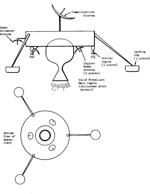
Fig. 1 shows a schematic representation of the spacecraft. A three-legged landing gear absorbs the r e s i d u a l energy at land- ing to limit the shock experienced b y the spacecraft b o d y a n d the scientific instruments. Stability during landing, for the expected tolerances in b o t h the v e r t i c a l and h o r i z o n t a l
components of the landing velocity, as w e l l as the expected variations in the surface s l o p e , is p r o v i d e d b y the w i d e spread of the landing l e g s .
TERMINAL DECELERATION P H A S E
The t e r m i n a l deceleration p h a s e of the landing operation b e - gins at an altitude of about 50 n a u t i c a l m i l e s above the lunar surface. The vehicle w i l l h a v e b e e n oriented through ground command such that its thrust axis is very nearly p a r a l l e l to the approach velocity v e c t o r . First, the vernier engines are reignited to achieve attitude control b y m e a n s of a differen- tially throttling control system. Shortly t h e r e a f t e r , at a n o m i n a l altitude of about ko n a u t i c a l m i l e s , the m a i n engine is fired.
During the m a i n engine p h a s e , n o guidance w i t h respect t o altitude-velocity p r o f i l e is incorporated. This results from the consideration that accurate m e a s u r e m e n t s b y t e r m i n a l sen- sors might b e difficult during this phase b e c a u s e of the h i g h a l t i t u d e , the effects of the large f l a m e , and the v i b r a t i o n environment. Instead, the system is designed to b e able to accommodate the p r o b a b l e tolerances in m a i n engine burnout altitude and velocity due to the aggregate of a l l error con- tributing s o u r c e s , such as t o t a l m a i n engine impulse, thrust l e v e l , uncertainties in altitude and velocity at initiation of b u r n i n g etc. The dispersions in staging altitude and velocity are represented b y a 99$ p r o b a b i l i t y ellipse shown in Fig. 2 .
A f t e r staging, the vernier engine thrust level is reduced to that w h i c h gives a net thrust a c c e l e r a t i o n of one lunar-g.
The spacecraft, w h o s e thrust direction h a s b e e n aligned to the v e r t i c a l during the short period b e t w e e n m a i n engine burnout and staging, descends at constant velocity. The t e r m i n a l sensors, n a m e l y an altimeter and three Doppler radars (located symmetrically about the vehicle thrust axis at a certain squint a n g l e ) , b e g i n to obtain altitude and velocity informa- tion in the b o d y coordinate reference system.
For v e r t i c a l descent, a constant deceleration trajectory is chosen in the h (altitude) - ζ (downward v e l o c i t y ) p h a s e p]_ane as the n o m i n a l . The end point (hf, if) on the tra- jectory is chosen to be at 100 ft and 10 fps w h i l e the n o m i - n a l thrust acceleration for the trajectory is 2 . 7 l u n a r - g1s · When the sensor data indicate that the spacecraft has de-
scended from the a c t u a l staging point A1 to a point Bt on the n o m i n a l t r a j e c t o r y (as shown in Fig. 2 ) , longitudinal or
vertical guidance "begins. This is done by throttling the total vernier thrust in such a way as to minimize the devia- tion between the actual and nominal trajectories. A short time later, lateral or horizontal guidance is initiated.
Lateral guidance takes the form of body maneuvering (i.e., thrust axis steering) in response to lateral velocity error in the body coordinate system. A time-varying gain is incorpo- rated to optimize the system for maximum effectiveness in reducing lateral velocity error while minimizing the maximum angle that the body axis attains from the local vertical.
The latter constraint arises from the consideration that proper radar sensor operation can only be achieved with rea- sonably small body angles with respect to the local vertical.
When the spacecraft velocity is reduced to 10 fps (nominally at a 100-ft altitude) as measured by the Doppler sensors, lateral guidance terminates and the thrust is reduced to 1 lunar-g level for a constant velocity descent. This point is hereafter referred to as "guidance termination," since closed loop commands of body steering and thrust level end at this time and the guidance system has only an engine shutoff calculation still to perform. The final 1-g descent phase absorbs any altitude dispersions existing at the 100-ft level so as not to contribute directly to landing velocity error.
It furthermore allows smoothing of approximately 7 sec of data at low altitude and low velocity in order to determine the engine shutoff with precision. When the calculated landing velocity is 20 fps, shutoff is effected. Nominally, this occurs at an altitude of 30 ft and a vertical velocity of 10 fps.
GUIDANCE RULES
Longitudinal (or VerticaJ) Channel
For guidance in the longitudinal channel, two basic rules of thrust acceleration control were considered. One rule in- volves a continuously adjusted acceleration trajectory obeying the relation
.2 . 2 , ζ - ζ
where ac = command acceleration g = lunar gravity
ζ = instantaneous downward velocity
ζ = "target" or offset velocity (= 10 fps)
h = instantaneous altitude
hf = "target" or offset altitude (= 100 ft)
In other words, when a deviation from the nominal phase plane trajectory is detected, the thrust is controlled to a value which will produce a new constant-acceleration trajectory through the target velocity and altitude.
Another possible rule is to force the spacecraft to cancel any measured deviation by returning to the nominal phase-plane trajectory. The guidance rule in this case is
ac = «H + Ka <έ - *d> t 2]
where a.^ is the nominal acceleration, is a gain factor which may be programmed as a function of time or altitude, and Z£ is the desired velocity corresponding to the particu- lar altitude h on the nominal trajectory. Thus
zd =
V
2(8^ - g) (h - hf) + zf 2 [3]If there were no errors, the methods would operate identically.
However, in the presence of errors, the second method is pre- ferable. A closer correspondence between the actual and nominal trajectories is obtained and a smaller variation in acceleration results, especially towards the end of the guidance phase.
Due to the fact that the spacecraft attitude is nearly
vertical during the greater portion of the solo vernier phase (particularly so near the end of guidance), Eqs'. 2 and 3 may be mechanized using slant range R in place of h and velocity along the instantaneous thrust axis in place of z. The guidance sensors, being mounted fixed in the body frame, yield the required R and vi data without the need of complex, non-constant matrix transformation.
In Eq. 1 , if the factor l/2 is replaced by a slightly larger number, the command acceleration is well behaved, in the presence of system errors, decreasing to 1 lunar-g at the end.
However, the time required for the maneuver is greater than for the nominally constant acceleration trajectory (with the factor 1 / 2 ) , thus increasing the gravity loss. Also the large variation in acceleration level can affect the dynamic opera- tion of the lateral channel.
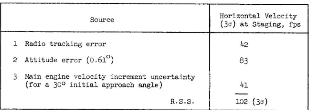
Lateral (or Horizontal) Channel
At the start of the solo vernier phase, a sizable horizontal velocity may be present. Table 1 lists the sources of error and the resulting horizontal velocity at staging. Landing stability considerations dictate that the 3-sigma residual horizontal velocity at impact be no more than 10 fps. Hence, there is a need for lateral steering during the solo vernier phase to remove most of the initial horizontal velocity.
The lateral guidance channel must therefore satisfy the following system requirements:
1) The system must be able to remove at least 100 fps of initial lateral velocity error.
2) The maximum angle 9m a x of the thrust axis from the vertical during the corrective process must be small enough to allow proper operation of the body-mounted velocity and
altitude sensors.
3) The angular acceleration and angular rate must be within the capability of the control system.
4) The attitude of the vehicle at the end of the guidance phase must be very nearly vertical.
5) The landing velocity must be less than 10 fps {3°) in the horizontal direction.
Two rules were seriously considered for lateral guidance:
Rule A: A linear steering system in which the vehicle thrust axis is directed at a computed angle from the local vertical in the trajectory plane. At the proper time, the angle is decreased at a constant rate to zero such that when the angle goes to zero, the lateral velocity goes to zero also.
Rule B: A proportional rate steering system in which the angle between the velocity vector and the thrust axis is used to generate angular rate commands in pitch and yaw in a manner to gradually reduce the angle to zero (but not to force this angle to be always zero as in an ideal gravity turn system).
The major advantage of Rule A is that it best fulfills the second requirement previously given. However, control of attitude in accordance with this rule requires dead-
reckoning attitude using body angular rates. To accomplish this, the required instrumentation and computation are
somewhat complex.
Rule Β requires no knowledge of either the lunar vertical or the vehicle attitude. The combined action of the longitudinal and lateral channels automatically forces the thrust axis to approach the lunar gravity vector at the end of guidance.
Because this rule results in a null-seeking system, errors in initial conditions or those due to transient disturbances, which might in a dead-reckoning system result in standoff errors, are largely cancelled out by the time guidance is completed. The only respect in which Rule Β appears inferior to Rule A is that it results in a slightly larger value of
&max« However, by proper choice of the gain function relating angular rate and error angle, a system based on Rule Β can meet all the stated requirements comfortably.
INSTRUMENTATION AND EQUATIONS Terminal Guidance Instrumentation
The block diagram for the overall terminal guidance instru- mentation is shown in Fig. 3· The computer accepts slant range from the altimeter, range rates from the three Doppler radars and thrust acceleration information from a longitudinal accelerometer. After proper data processing, the following fundamental quantities are obtained:
R = slant range along thrust axis to lunar surface
= velocity of spacecraft projected along roll (thrust) axis
V j = velocity of spacecraft projected along.pitch axis v^ = velocity of spacecraft projected along yaw axis
a = thrust acceleration
The computer generates the following guidance commands:
ac = command thrust acceleration u)jC = command pitch rate
U)kc = command yaw rate
The command acceleration is compared with the measured accel- eration and the difference is amplified and sent to the vernier engine valve controls for adjusting the total thrust level. The angular rate commands are sent directly to the attitude gyros.
In addition to the guidance commands, the computer also sends gimbal angle commands for steering a high gain communications antenna to maintain an Earth pointing despite body maneuvering
during the vernier solo phase.
Guidance Equations
The guidance equations for the various important functions are given in the following subsections.
1 Longitudinal guidance
v. -
1
- g) (R - hf) + zf c
This is in the same form as Eqs. 2 and 3 combined, except with
ih]
ζ (the vertical velocity) replaced by vi (the component of velocity along the thrust axis) and h (the altitude) re- placed by R (the slant range).
2 Lateral guidance
Ω . =
j e
Vv ν v, v.
[5]
v. v.
wkc f, (t) -£ = Κ1 =i -J.
1 v ' v. R v.
v.
R [6]
The gain function f-j_ (t) (chosen to be a constant Kf times the ratio V^/r) is nearly an invariant function of altitude due to the fact that the longitudinal guidance channel always forces the spacecraft towards the nominal vertical descent phase trajectory. Roughly, the ratio V.J_/R increases as the reciprocal of T, the time-to-go before guidance termination.
An upper limit is actually imposed on f-.(t) during the last few seconds of guidance in order to avoid guidance loop insta- bility. Also, the constant K! is made large during the first few seconds of guidance to achieve a rapid swing out of the thrust axis in the proper direction. For the major portion of the lateral guidance interval, however, K* is maintained at a modest value optimized for efficient steering out of lateral velocity combined with minimum body tilt angles.
3 Guidance termination
Guidance termination is defined as the instant when the thrust acceleration is returned to the 1-g level and lateral guidance is terminated by setting u)jC = = 0. This occurs when the measured vi is 10 fps at a nominal altitude of 100 ft.
To minimize the velocity error, guidance termination requires a timing more accurate than the basic 1-sec computation cycle, and a simple linear prediction is used to send this signal to the engines at the proper instant. The time to throttle down Δτ-^ is computed as
Δτ, [7l
As soon as Δτ^ becomes less than the computer repetition period plus the expected engine delay Δτ^, the computer waits for a time equal to
throttling signal.
Δτ, Δτ,Η and then sends the
h Shutoff
During the final 1-g descent, an accurate measure of the vertical velocity is obtained by simple averaging of all samples of v^.. The desired shutoff range or altitude is then computed to provide a nominal landing velocity of 20 fps.
Next, the time before cutoff Tc o is computed and compared with the sum of the computer repetition period and the
expected engine shutdown delay Δ τν· When Tc o becomes less than this sum the computer waits for a time equal to
Tc o - Δ τγ and sends the shutoff signal. The equations are as follow
v.
ι
V . η ι
Σ (average velocity) r=l n
[8]
co
CO
2 — 2 20 - v.
2g
R - R
- i — (shutoff range)
co v.
ι
(time to go before shutoff)
[9]
[10]
GUIDANCE LOOP DYNAMICS
The two guidance channels, longitudinal and lateral, are essentially closed-loop systems whose cross-coupling effect onto each other is negligible so long as the following two conditions are satisfied: The vertical descent adheres closely to the nominal trajectory; and the body tilt angle at any time during the guidance phase is small so that the
cosine of this angle is nearly unity.
For the spacecraft under consideration, both conditions are in fact fulfilled.
Longitudinal Channel Dynamics
For the case of zero lateral velocity, the relations between acceleration, velocity, and altitude may be obtained from in- spection of Eqs. 2 and 3· The block diagram of Fig. h shows the closed loop nature of the system. It should be noted that the system is basically nonlinear due to the nonlinear trans- fer function between the altitude h and the desired velocity Z £ . However, if the assumption is made that the actual tra- jectory followed does not deviate much from the nominal, it is possible to obtain a linear approximation for the system which involves only a time varying parameter.
For the nominal trajectory
zd = zf + (ajj - g) Τ [11]
where Τ is the time to go before guidance termination. Also
ô zd *Ν - 6 aN - g
5 h
V
2 (aN - g) (h - hf) + zf 2 Zd[ 1 2 ]
Defining the quantities
* [ 1 3] Δζ = ζ - nominal
^ = h - hnominal
[15]
Aa = a - anominal
A zwhere the terms in the right-hand members of Eqs. 1 3 through d = V ' " nominal l 6 correspond to the same instant of time, it may be shown that the block diagram of Fig. k is reducible to that of Fig. 5 in which only the perturbations are involved.
In practice, the time to go Τ decreases very nearly in a one to one correspondence with real time
(dT/dt) ^ [17]
The differential equation describing the dynamic behavior of the system of Fig. 5 is, with the utilization of Eq. 17
dT Κ
Zf + («Κ - g)
[18]
Eq. 1 8 , need not be a constant but may be any function of time. The special case of constant 1^ results in the follow- ing solution for the velocity error e
ζ + (a f v Ν
2 exp Κ (Τ - Τ ) [19]
g) T a 0
At guidance termination Τ equals zero and the ratio of the initial to the final velocity error is
z
r
+exp (Κ Τ )
v a cr [20]
This ratio is plotted against TQ for several values of
in Fig. 6. For large values of TQ, the reduction of initial velocity error is generally quite effective. However, as TQ decreases, the velocity error may actually increase towards the end. The latter is an inherent characteristic of the geometry, not a fault of the system. Fortunately, there is a better criterion for judging the system performance than βγ·
Since guidance termination is based on velocity information, concern is primarily with the altitude dispersion at this point. It may be shown that the altitude error between the actual and nominal trajectory corresponding to some value of ζ is
oh = -
Ô Z ,
Δζ Ah
öh_
δζ, (Δζ Δζά)
Eqs. 20 and 21 may be combined to give
Oh (0) = ôh (T ) exp ( - Κ Τ ) ο a ο
[21]
[22]
Hence, the altitude error diminishes rapidly in an exponential manner. As an example, suppose guidance begins at TQ =
50 sec and an initial altitude error of 1000 ft (equivalent to 20 fps in velocity) is assumed. Then, even with a 1^ of only 0 . 1 , the final altitude error is but 6 . 7 ft. In the actual system, 1 ^ is increased from 0 . 1 initially to about 0.3 at the end of guidance, and the residual altitude error due to initial offset becomes quite negligible. Analog simu- lation results have also verified the validity of the conclu- sions of this simple, linearized approach.
Lateral Channel Dynamics
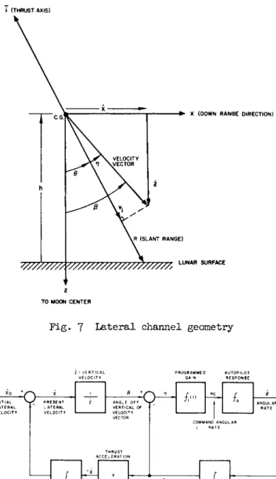
The geometry of the lateral channel is shown in Fig. 7 · For small values of β and Θ, the closed-loop representation of Fig. 8 applies. Assuming the control system (autopilot) response is essentially instantaneous, the differential equa- tion characterizing the guidance loop is
The form chosen for f-^(t) is fx( t ) =
X + X + X
V .
[23]
[24]
As long as the error angle η is small, the ratio V . /R is very nearly z/h. In terms of the time to go T, Eq. 23 may be rewritten as
Κ
- i t
zf Τ g) ^ dx
dT
djfc dT^
= 0 [25]
Using the approximate expression
i
~ zf + (a^ - g) Τ [26]to change t h e independent v a r i a b l e in Eq. 25, one m a y o b t a i n
* * ' 6 f i2 + 2 hf ( aN - g ) -
z/1 *
à χ'-
2ζ — + χ = 0 [27]
* N d z
Except for the last f e w seconds of guidance
•2 ^ ^ ^ , , · 2
ζ > > 2 hf ( a ^ - g ) - zf 2 [28]
T h u s , Eq. 27 m a y b e approximated b y the h o m o g e n e o u s linear d i f f e r e n t i a l equation
^ - β .2 d2x ^ - g
ζ — + χ = 0 [29]
2Κ' * N " d z2 ® H dz The solution of Eq. 29 is
m1 n u
x - ^ z + C g Z * [30]
w h e r e m1 and m ^ are the roots of the auxiliary equation
s t ; m - ^ ^ +( 1} m + 1 = 0 t] 3 1
Clearly, in order to effect a r e d u c t i o n of t h e l a t e r a l
velocity χ a s ζ d e c r e a s e s , the r e a l part of m-^ and m g must b e p o s i t i v e . A c t u a l l y , there is n o advantage in m a k i n g mi_ and complex at any event. The gain Kf actually chosen is such as to m a k e m ^ = Β^ · A n y increase in K*
tends to increase one and decrease the o t h e r , resulting in less effective velocity r e d u c t i o n . For the e q u a l root case
X
1 + m in —
^ ζ ) aN " * ß
ο Λ ο in —
m
[32]
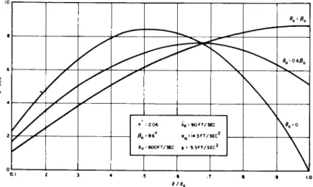
From Eq. 32 it is apparent that the lateral velocity reduction is also strongly dependent on the initial conditions. For the parameters involved for the spacecraft, K1 = 2.06 is the optimum choice resulting in m^ = m^ = m = 2 . 5 6 . Thus
χ χ
2 . 5 6
f. \2·5 6
- )
[33]Several response curves are shown in Fig. 9 · Curve A is for θ0 = 0, corresponding to the case where the optimum gain Kf
is used initially as well. Curve C is for θ = ßQ. This may be achieved by using a very large gain initially for a short time, forcing the thrust line into coincidence with the velocity vector and then switching over to the optimum gain.
Curve D is for the case where the logarithmic term disappears from Eq. 33· This can be achieved only through an under- damped response in θ/β and by switching the gain to the proper optimum value when θ has overshot past β with the exact ratio as indicated. Curve Ε is one for which the co- efficient of the logarithmic term is negative. Although not shown, the velocity error will become negative at some small value of z, indicating over-correction.
The actual Kf program places the response somewhere between Curves A and C Curve Β is representative. A large value of K! of about 1 5 is used initially for three seconds, after which the lower value of 2.θ6 is used. The reduction in lateral velocity is more than adequate for the initial magni- tudes anticipated. The approximate analysis is accurate down to a ζ of about 80 fps corresponding to a time to go of 8 sec. If ζ and χ are assumed to be 600 and 100 fps, respectively,°the resiâual χ will be about 4 . 5 fps at this time. Further correction during the last few seconds results in a final χ of less than 0.5 fps, as verified through analog simulation studies.
The body attitude response curves are found through the following relation
Fig. 10 is a plot of θ vs z/z for several values of θ . A g a i n it is seen that the choice of θ somewhere b e t w e e n 0 and ßQ has a beneficial effect of reducing the maximum value of Θ.
CONCLUSIONS
A n a l y s i s and tests of the l a n d i n g dynamics of the spacecraft showed that stability is critically dependent u p o n k e e p i n g the two components of t o u c h d o w n velocity w i t h i n prescribed b o u n d s . Conservative allowances of + 5 and 10 fps w e r e t h e n m a d e for the v e r t i c a l and h o r i z o n t a l velocity e r r o r s , respectively. A detailed error a n a l y s i s , b a s e d o n anticipated tolerances in the a c t u a l instrumentation, revealed the following 3-s i g m a landing velocity errors
V e r t i c a l velocity error (3σ) 3 fps H o r i z o n t a l velocity error (3o) 10.3 fps The v e r t i c a l velocity error is due p r i m a r i l y to a n assumed error of + 10 ft (3σ) in the altimeter r e a d i n g at vernier engine shutoff. The h o r i z o n t a l velocity error is almost com- p l e t e l y due to a n assumed r a n d o m b i a s error of 3 fps (3<0 in each Doppler radar beam.
The p r i n c i p a l errors in landing velocity a r e , t h e r e f o r e , not inherently a result of any deficiency or over-simplification of the guidance p h i l o s o p h y but are rather due t o sensor limita- t i o n s . T h e r e f o r e , if sensor a c c u r a c y should be b e t t e r t h a n assumed, a n even lower velocity landing could b e achieved, possibly less t h a n 10 f p s .
REFERENCES
1 Hord, R. Α., "Relative motion in the terminal phase of interception of a satellite or a ballistic missile/' NACA TN 4399 ( I 9 5 8 ) .
2 Brady, F. H. and Green, W. G., "Deceleration control of space vehicles," ITT Laboratories Serial No. 2052 ( 1 9 5 9 ) · 3 Green, W. G., "Logarithmic navigation for precise guidance of space vehicles," IRE Transactions on Aerospace and Naviga- tional Electronics, Vol. ANE-8, No. 2 ( 1 9 6 1 )
Source Horizontal Velocity
(3σ) at Staging, fps
1 Radio tracking error 42
2 Attitude error (0.6l°) 83
3 Main engine velocity increment uncertainty
(for a 30° initial approach angle) 41 R.S.S. 102 (3σ)
Table 1 Horizontal velocity error at staging
Fig. 1 Schematic representation of spacecraft
D O P P L E R 2
A C C E L E R O M E T E R
S L A N T R A N G E ( P U L S E S )
A N T E N N A G l M B A L C O M M A N D S
«c ( E L E V A T I O N ) f ?c ( A Z I M U T H )
P I T C H R A T E COMMAND u j C I R A T E C O M M A N D
C O M M A N D T H R U S T A C C E L E R A T I O N
M E A S U R E D T H R U S T A C C E L E R A T I O N ( A N A L O G F O R M )
A T T I T U D E C O N T R O L
S Y S T E M
_ T O V E R N I E R E N G I N E V A L V E C O N T R O L
Fig. 3 Terminal guidance instrumentation
κ A c c e l e r a t i o n I n c r e m e n t a
' ^ aN- g ) ( h - hf) + zf
h Closed-loop representation of longitudinal channel
i ( T H R U S T AXIS)
VELOCITY V/ E C T O R
X ( D O W N R A N Q E D I R E C T I O N )
VR ( S L A N T R A N G E )
Ζ T O MOON C E N T E R
L U N A R S U R F A C E
Fig. 7 Lateral channel geometry
I N I T I A L L A T E R A L V E L O C I T Y
P R E S E N T L A T E R A L V E L O C I T Y
Ε O F F V - / A N G L E 01 V E R T I C A L OF VELOCITY VECTOR
;
;
/,··• «c 8
/,··•
t
ANGULAR R A T E
Fig. 8 Lateral channel dynamic representation
K1 = 2 0 6 Xo : 9 0 F T / S E C 0O= 8 6 ° 0N- - I 4 3 F T / S E C 2 2 0= 6 O O F T / S £ C 9 = 5 3 F T / S E C 2 K1 = 2 0 6 Xo : 9 0 F T / S E C 0O= 8 6 ° 0N- - I 4 3 F T / S E C 2 2 0= 6 O O F T / S £ C 9 = 5 3 F T / S E C 2
2 3 4 5 .6 . 7 β .1
Fig. 10 Body attitude vs. vertical velocity