Comment on “Resistance of a digital voltmeter: teaching creative thinking through an inquiry-based lab”
Zoltan Gingl and Robert Mingesz
Department of Technical Informatics, University of Szeged, Árpád tér 2, 6720 Szeged, Hungary E-mail: gingl@inf.u-szeged.hu
Abstract
Teaching about measurements and showing examples of instruments’ non-ideal behaviour are important in physics education. Digital multimeter input impedance analysis is perfect for this, since these instruments are easily available, precise enough, have good value/price ratio and represent modern technology. A recent paper (2018 Phys. Educ. 53 053005) demonstrates how the investigation of the input impedance of a digital multimeter can be used in education.
However, we think that some more discussion is needed to make it more complete.
Methods to measure the input impedance
Two methods are presented in the paper [1] to measure the input impedance of a digital multimeter (DMM) in voltage measurement mode:
Use another DMM in resistance measurement mode. In this case a constant current is forced through the input impedance and the voltage drop is measured.
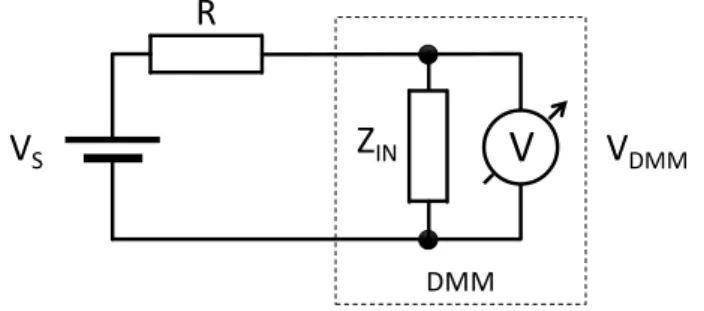
Apply a voltage source VS, measure the voltage VDMM on a known value resistor R and measure the current I flowing in the circuit (see figure 1). Simple calculation gives the result:
𝑍𝐼𝑁= 𝑅 ∙𝑉𝐷𝑀𝑀 𝐼 𝑅 −𝑉𝐷𝑀𝑀
𝐼
(1)
Figure 1. Arrangement to measure the input impedance ZIN of the voltmeter [1]. The readings are VDMM=9.3 V, I=1.8 μA and R=10.6 MΩ.
V
SR
V
DMMA
DMM
Z
INV
I
Accepted manuscript
Citation: Zoltan Gingl and Robert Mingesz 2019 Phys. Educ. 54 056502 DOI: https://doi.org/10.1088/1361-6552/ab2bdd
The authors’ observations could suggest that the accuracy is almost the same for the two methods (they obtained 10.0 MΩ and 10.1 MΩ), however, it is not the case.
Accuracy analysis
The accuracy of the first method can be obtained using the specifications of the DMM in Ohmmeter mode. It is 2%+5 digits for the DMM the authors used (BK Precision 388B) when the reading is 10.00 MΩ, so the error can be as high as ±0.25 MΩ (10.00 MΩ·0.02 and 0.01 MΩ per digit). This means that the input impedance falls in the range of 9.75 MΩ to 10.25 MΩ.
The second method is much less accurate. Only a very lucky situation is shown in the paper [1], when the deviation of the calculated input impedance from the nominal value is only about 1%.
Even for a perfect DMM, just due to the finite resolution, any voltage between 9.25 V and 9.35 V results the reading of 9.3 and 1.8 corresponds to the range of 1.75 μA to 1.85 μA. Figure 2 shows a simple simulation how the calculated value can vary due to this quantisation error. The voltage VS is swept in a range, the voltage VDMM and current I are calculated and rounded to 0.1 units, then the input impedance is calculated using equation (1).
Figure 2. Input impedance as a function of the source voltage in a simulated measurement using ZIN=10 MΩ and R=10.6 MΩ.
In addition, according to the DMM specifications, the reading of 1.8 means that the current falls in the range of 1.68 μA to 1.92 μA (error: 1%+1 digit ≈ 0.018 μA+0.1 μA ≈ 0.12 μA). Similarly, the reading of 9.3 means that the voltage is between 8.79 V and 9.81 V (bench DMM, 0.1%+5 digits
≈ 0.0093 V+0.5 V ≈ 0.51 V). Therefore, the 9.3 V and 1.8 μA values only mean, that the input impedance is in the following range:
𝑍𝐼𝑁,𝑚𝑖𝑛= 10.6 ∙8.79 1.92 10.6 −8.79
1.92
MΩ ≈ 8.06 MΩ (2)
9.4 9.6 9.8 10 10.2 10.4 10.6
9 9.1 9.2 9.3 9.4 9.5 9.6 9.7 9.8 9.9 10
C al cul at ed inp ut im pe da nce [ M Ω ]
Voltage [V]
𝑍𝐼𝑁,𝑚𝑎𝑥= 10.6 ∙9.81 1.68 10.6 −9.81
1.68
MΩ ≈ 13.00 MΩ
Assuming, that the 10.6 MΩ resistor is measured with an error of 2%+5 digits (10.338 MΩ < R < 10.862 MΩ), the range is a bit wider:
𝑍𝐼𝑁,𝑚𝑖𝑛= 10.862 ∙8.79 1.92 10.862 −8.79
1.92
MΩ ≈ 7.91 MΩ
𝑍𝐼𝑁,𝑚𝑎𝑥= 10.338 ∙9.81 1.68 10.338 −9.81
1.68
MΩ ≈ 13.42 MΩ
(3)
Since the current is low, it can’t be measured accurately, this is the main source of the error.
However, it is a good chance to teach about how to use the errors specified in the manual of the DMM and also to demonstrate the effect of the quantisation error. The students can vary the voltage to see the impact on the calculated input impedance value. They can learn that it is normal to have measurement errors and that the reading is not the real value.
An additional method
There is a third, frequently used method. A voltage source can be connected to the voltmeter via a known value resistor, see figure 3.
Figure 3. A voltage source and a resistor can be used to measure the ZIN input impedance.
The input impedance can be calculated as:
𝑍𝐼𝑁= 1 𝑉𝑆 𝑉𝐷𝑀𝑀− 1
𝑅 (4)
The procedure of obtaining ZIN can be as follows:
apply a VS that falls in the upper half of the measurement range to have good resolution,
measure VS directly with the DMM,
insert a 10 MΩ 1% tolerance resistor R as shown in figure 3,
read VDMM without changing the range.
For example, assuming 3.012 V and 1.507 V readings in the 4 V range and using the specifications in the datasheet (0.5%+1 digit error in voltmeter mode) we get
R
V
SZ
INV V
DMMDMM
2.996 V ≤ VS ≤ 3.028 V,
1.498 V ≤ VDMM ≤ 1.516 V,
9.9 MΩ ≤ R ≤ 10.1 MΩ.
Substituting these into equation (4) ZIN can be anywhere in the range 𝑍𝐼𝑁,𝑚𝑖𝑛= 1
3028 1.498 − 1
9.9 MΩ ≈ 9.69 MΩ
𝑍𝐼𝑁,𝑚𝑎𝑥= 1 2996 1.516− 1
10.1 MΩ ≈ 10.34 MΩ
(5)
This arrangement has some advantages:
Only a single instrument is needed, the DMM is used in its highest accuracy mode.
The accuracy is fairly good.
It can be easily implemented on devices that have voltage inputs like Arduino [2,3].
The series resistor’s value can be gradually reduced to see how the voltage
measurement error caused by the input impedance decreases and gets insignificant below a threshold.
Should we worry so much about accuracy in a school experiment?
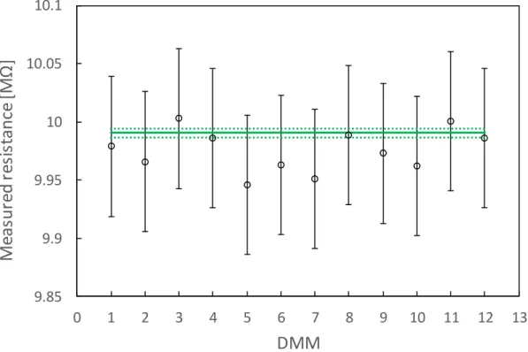
The accuracy of a certain DMM can be considerably better than the specified accuracy valid for all DMMs of the same type. In order to demonstrate the performance of DMMs, we have measured a 10 MΩ 1% tolerance resistor with 12 general purpose DMMs of the same type (UNI- T UT60H) and with a high-end 6.5 digit DMM (Agilent 34410A) to have an accurate reference value. The readings and errors can be seen in table 1 and figure 4.
DMM Reading
[MΩ]
Error limits (0.5%+10 digits) Deviation Minimum [MΩ] Maximum [MΩ] MΩ %
1 9.979 9.919 10.039 -0.012 -0.12
2 9.966 9.906 10.026 -0.025 -0.25
3 10.003 9.943 10.063 +0.012 +0.12
4 9.986 9.926 10.046 -0.005 -0.05
5 9.946 9.886 10.006 -0.045 -0.45
6 9.963 9.903 10.023 -0.028 -0.28
7 9.951 9.891 10.011 -0.040 -0.40
8 9.989 9.929 10.049 -0.002 -0.02
9 9.973 9.913 10.033 -0.018 -0.18
10 9.962 9.902 10.022 -0.029 -0.29
11 10.001 9.941 10.061 +0.010 +0.10
12 9.986 9.926 10.046 -0.005 -0.05
Table 1. Readings of 12 DMMs during the measurement of a 10 MΩ 1% tolerance resistor. The deviation is referenced to the reading of the high-accuracy DMM, 9.99062 MΩ.
Figure 4. Readings of 12 DMMs during the measurement of a 10 MΩ 1% tolerance resistor.
The error bars correspond to the 0.5%+10 digits accuracy specification. The solid line represents the reading of the high accuracy DMM, 9.99062 MΩ. According to its specification, the real value falls within the region bounded by the dotted lines.
Although the accuracy of the DMMs is found to be better than the specified value, it can only be determined using a high accuracy reference. Without this only the specified values are known and should be used. One may say that it is not a serious concern in a school experiment, the readings are accurate enough. It is not a problem if the accuracy is not high, but we do think that students should be taught that any instrument has its specified accuracy what should always be kept in mind [2,4]. They should be able to calculate the error of the measurement. Our accuracy analysis shows simple examples how to work with DMM error specifications in agreement with the manufacturer’s technical article
(https://bkprecision.desk.com/customer/en/portal/articles/1535309-how-to-read-accuracy- specifications).
Acknowledgments
This study was funded by the Content Pedagogy Research Program of the Hungarian Academy of Sciences.
References
1. Stojilovic N and Isaacs D E 2018 Resistance of a digital voltmeter: teaching creative thinking through an inquiry-based lab Phys. Educ. 53 053005
2. Makan G, Mingesz R and Gingl Z 2019 How accurate is an Arduino Ohmmeter? Phys.
Educ. 54 033001
3. Kinchin J 2018 Arduino and cheap thermistor to make a simple temperature sensor Phys.
Educ. 53 063008
4. Gingl Z and Mingesz R 2019 Voltmeter in series? Phys. Educ. 54 045017 9.85
9.9 9.95 10 10.05 10.1
0 1 2 3 4 5 6 7 8 9 10 11 12 13
![Figure 1. Arrangement to measure the input impedance Z IN of the voltmeter [1]. The readings are V DMM =9.3 V, I=1.8 μA and R=10.6 MΩ](https://thumb-eu.123doks.com/thumbv2/9dokorg/1285964.102817/1.892.257.618.756.1083/figure-arrangement-measure-input-impedance-voltmeter-readings-dmm.webp)