Development and characterization of novel microelectrode arrays for neurophysiology
Ph.D. dissertation
Gergely Márton
Semmelweis University
János Szentágothai School of Neurosciences
Supervisor: Dr. István Ulbert, D.Sc.
Opponents: Dr. András Czurkó, Ph.D.
Dr. László Négyessy, Ph.D.
Qualifying exam commitee, chair: Dr. Béla Halász, member of the HAS Qualifying exam commitee: Dr. László Acsády, Ph.D.
Dr. Zoltán Somogyvári, Ph.D.
Budapest
2015
2
Contents
List of abbrevations ... 5
1. INTRODUCTION ... 7
1.1. Electrophysiology ... 7
1.1.1. Overview ... 7
1.1.2. In vivo extracellular measurements ... 8
Local field potential ... 8
Unit activities ... 9
1.1.3. Electrocorticography ... 10
1.1.4. Acute in vivo measurements on laboratory animals ... 10
1.2. Electrode properties ... 12
1.2.1. Surface conditions ... 12
1.2.2. Impedance ... 13
1.2.3. Roughness factor ... 15
1.2.4. Biocompatibility ... 17
1.3. Microelectrode array types ... 18
1.3.1. Fine wires ... 18
1.3.2. Silicon-based devices ... 19
Michigan arrays ... 19
The Utah array... 21
Other silicon-based extracellular electrode arrays ... 22
1.3.3. Polymer-based devices ... 24
1.3.4. Microelectrode arrays with special features ... 26
Three-dimensional arrays ... 26
Microfluidic channels... 27
Waveguides for optogenetics ... 29
High surface area, low impedance microelectrodes ... 29
2. SPECIFIC AIMS ... 31
2.1. In vivo recordings with silicon-based probes of extreme shaft length... 31
2.2. Testing in vivo durability of platinized platinum electrodes ... 31
2.3. Development and characterization of polymer-based microelectrode arrays with protruding sensor sites ... 32
3
2.4. Development and characterization of a multimodal, polymer-based
microelectrode system ... 33
3. METHODS ... 34
3.1. Methods related to in vivo recordings with silicon-based probes of extreme shaft length ... 34
3.1.1. Design and fabrication ... 34
3.1.2. In vivo measurements ... 37
3.1.3. Signal acquisition and data processing ... 38
3.2. Methods related to in vivo durability tests of platinized platinum electrodes ... 39
3.2.1. Silicon probes ... 39
3.2.2. Basic electrochemical measurements ... 40
Electrochemical impedance spectroscopy... 40
Cyclic voltammetry ... 40
3.2.3. Electrolytic deposition of platinum ... 40
3.2.4. In vivo measurements ... 42
3.3. Methods related to the development and characterization of polymer- based microelectrode arrays with protruding sensor sites ... 43
3.3.1. Design and fabrication ... 43
3.3.2. In vitro and in vivo characterization ... 45
3.4. Methods related to the development and characterization of a multimodal, polymer-based microelectrode system ... 47
3.4.1. Fabrication... 47
3.4.2. Assembly and packaging... 48
3.4.3. Electrode impedance measurement and reduction methods ... 49
3.4.4. In vivo characterization ... 49
4. RESULTS AND DISCUSSION ... 51
4.1. Results and discussion concerning in vivo recordings with silicon- based probes of extreme shaft length ... 51
4.2. Results and discussion concerning in vivo durability tests of platinized platinum electrodes ... 55
4.2.1. Results of in vitro measurements ... 55
4
4.2.2. Variation of impedance magnitudes in vivo ... 56
4.2.3. Effects of 12 acute implantations on the electrodes ... 57
4.2.4. Noise of different electrodes after 12 implantations ... 59
4.3. Results and discussion concerning the development and characterization of a novel polymer-based microelectrode arrays with protruding sensor sites ... 61
4.4. Results and discussion concerning the development and characterization of a polymer-based multimodal microelectrode system ... 65
4.4.1. Microfabricated and assembled devices... 65
4.4.2. Original and reduced electrode impedances in saline ... 66
4.4.3. In vivo experimental results and discussion... 67
5. CONCLUSIONS ... 71
6. SUMMARY ... 72
7. ÖSSZEFOGLALÓ ... 74
8. REFERENCES ... 76
9. AUTHOR’S PUBLICATION LIST ... 90
9.1. Papers closely related to the PhD dissertation ... 90
9.2. Papers not closely related to the PhD dissertation ... 90
10. ACKNOWLEDGEMENTS ... 92
5
List of abbrevations
AP Anteroposterior
BBB Blood-brain barrier BMI Brain-machine interface CED Convection enhanced delivery
CMOS Complementary metal–oxide–semiconductor CPE Constant phase element
CSD Current source density
CV Cyclic voltammetry
DG Dentate gyrus
DL Double layer
DRIE Deep reactive ion etching ECoG Electrocorticography EDC Electronic depth control EEG Electroencephalography
EMG Electromyography
FDA U.S. Food and Drug Administration
FIB Focused ion beam
LFP Local field potential LTP Long term potentiation MEA Microelectrode array
MEMS Microelectromechanical systems
MFA Institute for Technical Physics and Materials Science of the RCNS-HAS (Műszaki Fizikai és Anyagtudományi Kutatóintézet, MTA-TTK)
ML Mediolateral
MUA Multiunit activity
nRT Thalamic reticular nucleus PDMS Polydimethylsiloxane Pt/Pt Platinized platinum
6
RCNS-HAS Research Centre for Natural Sciences of the Hungarian Academy of Sciences (MTA-TTK)
RIE Reactive ion etching
RF Roughness factor
RMS Root mean square
SEM Scanning electron microscope SNR Signal-to-noise ratio
SOI Silicon-on-insulator SUA Single unit activity
TC Thalamocortical
UIEA Utah intracortical electrode array
VPL Ventral posterolateral nucleus (of the thalamus) VPM Ventral posteromedial nucleus (of the thalamus)
7
1. INTRODUCTION
1.1. Electrophysiology 1.1.1. Overview
Electrodes make the detection of potential changes within, or in the vicinity of a domain containing living cells possible by converting ionic currents, propagating in aqueous solutions into currents of electrons, propagating in metals or semiconductors.
They are utilized by the majority of clinical and experimental neuroscience techniques, such as in vitro and in vivo electrophysiology, electrocorticography (ECoG), electromyography (EMG), electroencephalography (EEG), etc.
During in vitro experiments cultured neurons or brain slices are typically observed. In the majority of these studies, micropipettes are used in order to detect potential changes within the extracellular space, monitor membrane potentials of specific cells, or determine conductivity values of membrane regions, which are regulated by ion channels. Insulated metal wires can also be utilized for extracellular recordings, or for regulating the membrane potentials. In vivo extracellular electrophysiology allows neuroscientists to observe behavior of cells, cell populations or more extent neural structures in their natural physiological environment, without violating their - usually extremely complex - connections with other parts of the brain.
This is achieved by implanting probes into the tissue. ECoG and EEG are practices of recording electric activity from the surface of the cerebral cortex and the scalp, respectively. Spontaneous activity and evoked potentials can be examined with both methods. A great advantage of EEG is its noninvasivity, however, its spatial and temporal resolution is low due to the filtering effect of the skull.
EEG and in vitro measurements are not directly related to this thesis, whereas in vivo extracellular measurements and ECoG are. Therefore the latter two methods are detailed in the following sections.
8
1.1.2. In vivo extracellular measurements
Local field potential
Cell membranes can be described as high impedance elements, with mostly capacitive characteristics, yet as a result of the conductive extracellular space, the neural tissue can be approximated as an ohmic conductor medium, with inhomogenity and anisotropy (Goto et al., 2010; Hoeltzell and Dykes, 1979). Due to the finite conductivity of the tissue, transmembrane currents give rise to a potential field. The fluctuations of the voltage at a certain point of the brain, which can be measured with respect to the voltage in a reference point, are usually divided into two signal types: unit activities, i.e.
the spikes generated by action potentials of neurons in the vicinity of the observed location, and variations of the local field potential (LFP), i.e. potential changes of other sources. The fact that LFP is not simply the result of superposing action potentials has been revealed early by Eccles (Eccles, 1951), who proposed that LFP is rather generated by postsynaptic currents. Since then, the contribution of other factors to the LFP has been described, e.g. afterhyperpolarization following action potentials, calcium spikes, transmembrane currents of glial cells, etc. (Buzsáki et al., 2012).
LFP signals are frequently utilized for current source density (CSD) analysis, during which current sinks and sources observed from the viewpoint of the extracellular space are evaluated. Assuming the potential field (φ) and the conductivity tensor (σ) are known in a domain, and the magnetic effects can be neglected, the source distribution (I) can be calculated:
(1.1.)
where ∇2φ is the second spatial derivative of the potential field. CSD allows the analysis of neural events with superior resolution compared to field potentials (Freeman and Nicholson, 1975; Nicholson and Freeman, 1975).
9 Unit activities
With an electrode implanted into the extracellular space, the detection of action potentials is possible as well (Woldring and Dirken, 1950). These single and multiple unit activities (SUAs, MUAs) can vastly increase the information content of extracellular recordings. The firing patterns of cells that contain their soma or axon in the vicinity of the probe yield information about the functions of the monitored tissue region. This allows functional mapping of most parts of the brain, e.g. the thalamus and neocortical regions (Komura et al., 2005; Metin and Frost, 1989). Hippocampal place cells of a rat are active when the animal is in a certain place of its environment (O'Keefe and Conway, 1978; O'Keefe and Dostrovsky, 1971), while grid cells in the entorhinal cortex fire when the rat positions itself into a node of a triangular spatial array (Hafting et al., 2005; Moser et al., 2008). SUA recordings in the human hippocampus revealed neurons that correspond to other, non-spatial related memory elements as well (Gelbard- Sagiv et al., 2008). Activity patterns of some neurons in the human amygdala showed that cells in the nuclei encode or compute stimulus values during decision making (Jenison et al., 2011).
Usually, SUAs of many neurons can be detected during a recording session. Unit activity clustering, or spike sorting is a technique used for reproducing spike trains of individual neurons (Takekawa et al., 2010). Simulations showed that action potential waveforms of maximum 8-10 cells can be classified (Lewicki, 1998; Pedreira et al., 2012). Mathematical algorithms have been developed in order to automate the sorting process (Quiroga et al., 2004; Rutishauser et al., 2006; Vargas-Irwin and Donoghue, 2007).
Determining the location of a neuron that generates unit activities, with respect to the electrode is a much more complicated matter than spike sorting. A special CSD method (spike CSD) was developed in order to reconstruct current source distributions of a single neuron during action potential generation and to determine cell-electrode distance (Somogyvari et al., 2012).
The information extracted from unit activity analysis can be exploited for developing high quality brain-machine interface (BMI) systems with cortically implanted extracellular microelectrodes. Such systems can be used to offer a speech-
10
deprived person a new channel of communication, which circumvents the individual’s sub-cortical nervous system in case of its impairment (Bartels et al., 2008; Brumberg et al., 2010; Guenther et al., 2009; Hochberg et al., 2006). Signals gained by extracellular electrodes implanted into the motor cortex can be utilized to control prosthetic limbs purely with thoughts (Hochberg et al., 2006; Homer et al., 2013; Truccolo et al., 2008;
Velliste et al., 2008).
1.1.3. Electrocorticography
ECoG, which is sometimes referred to as intracranial EEG, is a method comprising electrodes placed onto the brain surface (Matsuo et al., 2013). It can be used for functional mapping of various cortical regions, e.g. in the vibrissa/barrel field of rat neocortex (Jones and Barth, 1999).
In the clinics, ECoG is widely used during treatment of patients suffering from epilepsy, whose condition necessitates surgical resection (Asano et al., 2005; Kuruvilla and Flink, 2003; Ojemann, 1997; Sugano et al., 2007). Such surgeries require precise localization of the epileptogenic zones. Due to its high spatial resolution and signal-to- noise ratio (SNR) compared to EEG, ECoG is more suitable for this purpose (Hashiguchi et al., 2007). The technique is employed not only to assess the location of the irritative zones from ictal spike and interictal epileptiform activity, but also for functional mapping to avoid causing damage to critical regions. Furthermore, ECoG is employed to ascertain that the entire epileptogenic zone was resectioned.
Similarly to extracellular electrophysiology, ECoG is also a promising method in the aspect of creating BMIs for either brain-actuated prosthetic limbs (Graimann et al., 2004; Scherer et al., 2009) or speech restoration (Kanas et al., 2014; Spencer et al., 2010).
1.1.4. Acute in vivo measurements on laboratory animals
The in vivo characterization of neural probe prototypes and other novelties presented in this thesis will confine itself to acute measurements on laboratory rats.
Chronic implantation of the probes for neuroscientific experiments, as well as their
11
utilization in the clinics open further possibilities, yet they are more complex, and exceed the subject of this thesis.
Acute in vivo experiments revealing the principals of long term potentiation (LTP) were carried out on anesthetized rabbits (Bliss and Lomo, 1973). Pairs of stimulating (tungsten wire) and recording (NaCl filled glass pipette) electrodes were implanted into the perforant path and the dentate gyrus (DG) of the hippocampus, respectively, into both hemispheres of the animals, with micromanipulators. The experiments showed that the strength of the synapses between the entorhinal cortex neurons and the granule cells of the DG can be increased by tetanic stimulation of the perforant path. Further findings based on these experiments gave insight to the cellular mechanisms of synaptic plasticity, which plays a fundament role in learning and memory functions of the brain (Bliss and Collingridge, 1993; Cooke and Bliss, 2006).
Acute in vivo experiments are performed for the analysis of neural activity during sleep, too. In the majority of these studies, the animals are anesthetized with urethane (Metherate and Ashe, 1993; Toth et al., 2008) and/or a mixture of ketamine-xylazine (Sachdev et al., 2004). During deep anesthesia and natural sleep, spontaneous activity in the neocortex shows low frequency oscillations. Each period of the oscillation can be divided to two alternating states. Active (upstate) periods, when cortical cells generate action potentials frequently are followed by inactive (downstate) periods, when spikes occur sparsely (Chauvette et al., 2011; Chauvette et al., 2010). The firing rate strongly correlates with membrane potential fluctuations (Metherate and Ashe, 1993). The effects of peripheral stimulations can be measured on the cortex during sleep as well, including evoked field potentials and elevated unit activity (Toth et al., 2008). This allows e.g. the investigation of mechanisms in the barrel field that are triggered by whisker stimuli (Sachdev et al., 2004), or the mapping of auditory functional topography (Hackett et al., 2011).
12
1.2. Electrode properties
Before demonstrating various types of neural electrodes and electrode arrays, I touch upon some properties that need to be kept in sight during development and utilization of such devices.
1.2.1. Surface conditions
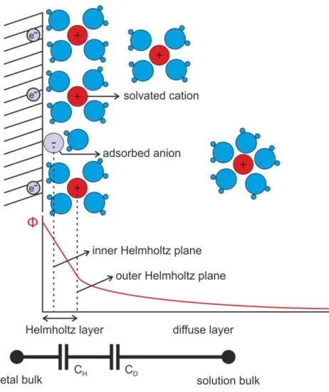
The surface conditions of a microelectrode are of high importance, since this is the area through which the ionic currents of the neural tissue communicate with the electron-currents of the sensor or stimulator devices. Non-toxic noble metals such as gold (Au), platinum (Pt) and iridium (Ir) are commonly used as microelectrode materials, because of their corrosion resistance (Heim et al., 2012b). According to the Gouy-Chapman model, when such metals are immersed into electrolytes, an electrical double layer (DL) will develop in the vicinity of their surface. The DL contains the Helmholtz planes, formed by dehydrated ions adsorbed to the surface and hydrated ions closely attracted to it by the Coulomb force. The thickness of the Helmholtz layer is of the order of an ionic radius, i.e., 2 to 4 Å. The diffuse, or Gouy-Chapman layer is much less compact. It contains mobile ions, which are distributed according to the mechanics of electrostatic interaction and thermal diffusion (Yang et al., 2004). The electric field (i.e. the negative of the potential gradient) generated by the charges which are accumulated on the surface of the metal is shielded by the ion concentration gradient in the DL, making the complete structure electroneutral in a relaxed state.
13
Fig. 1.1. Schematics illustrating the electrical double layer on the surface of a polarizable electrode. The Helmholtz layer contains ions adsorbed or electrostatically attracted to the surface. The diffuse layer contains mobile, solvated ions. Illustration based on Fig. 9. of (Wise et al., 1970).
1.2.2. Impedance
Considering the system illustrated in Fig. 1.1. as an electrical circuit, the Helmholtz and diffuse layers can be roughly approximated as capacitances (CH and CD, respectively), which will dominate the response of a polarizable electrode to an alternating current or voltage. The impedance of the electrical DL can be unified into a total capacitance, yet due to a phenomenon called frequency dispersion, a more precise approximation can be obtained by using a constant phase element (CPE) (Pajkossy et al., 1996; Zoltowski, 1998), which has an impedance of
14
(1.2)
where i is the imaginary unit, ω is the angular frequency, Q and α are frequency- independent parameters of the CPE. For α = 1, the CPE is a capacitance, for α = 0.5, it is a Wartburg element, and for α = 0, a resistance. The CPE can only model ideally polarizable electrodes. In order to achieve a more realistic illustration, a parallel resistive element (RCT) is often included, corresponding to faradic charge transfer between the metal and the electrolyte. Furthermore, a spreading resistance (RS) is applied serially, which represents the resistance of the solution around the electrode. In case of microelectrodes with small geometric area, this is an important element.
The thus assembled model was detailed previously (Franks et al., 2005;
Zoltowski, 1998) and is shown in Fig. 1.2. In reality, the situation can be even more complex, if we take into consideration e.g. the resistance of the wiring, or the finite impedance between two different channels in a multielectrode system. In case of neural electrodes, the relatively low (< 20 kHz) biologically relevant frequencies ensure the usefulness of this simple model.
Fig. 1.2. Advanced equivalent circuit model of a non-ideally polarizable electrode. The constant phase element (CPE) corresponds to the double layer, the charge transfer resistance (RCT) models the behavior of faradic processes. These two elements are characteristics to the electrode surface conditions, while the solution resistivity (RS) depends on the chemical and
15
geometric properties of the aqueous media surrounding the electrode. The model was adapted from (Zoltowski, 1998) and (Franks et al., 2005).
Electrodes must be as noiseless as possible, when functioning as recording devices and they must be capable of injecting sufficient amount of charge into the tissue, when employed as stimulators. Although the influence of electrode impedance to the performance is subtle and not thoroughly understood, most theories and experiments indicate that decreased impedance results in improved recording and stimulation capabilities (Du et al., 2011; Ferguson et al., 2009; Heim et al., 2012a; Keefer et al., 2008; Liu et al., 2008; Scott et al., 2012). The root mean square (RMS) of thermal noise is proportional to the square root of the real part of the impedance (Ferguson et al., 2009; Liu et al., 2008), and reducing it has proven to be an effective way to increase SNR of recording electrodes (Du et al., 2011; Scott et al., 2012). Lowering the impedance of stimulating devices allows higher amount of charge to be injected into the extracellular space of the targeted tissue before causing electrolysis (Mailley et al., 2004; Merrill et al., 2005).
1.2.3. Roughness factor
As shown in Fig. 1.3., the effective surface area of an electrode determines the extent of the surface where the electrolyte comes into contact with the electron- conductive material. This area contains the microscopic irregularities of the surface and differs from the geometric area of the electrode, i.e. its ―footprint‖ size from a macroscopic point of view. The roughness factor is the ratio of the effective surface and the geometric areas.
Increased electrode surface area causes higher double layer capacitance and lower charge transfer resistance, which both mean lower impedance, therefore higher SNR.
Increasing the geometric area of the electrodes in order to reduce their impedance is not only limited by probe shaft dimensions, but could worsen recording properties of action potentials from individual neurons (Moffitt and McIntyre, 2005). A theoretical study on factors determining the SNR suggests that increasing geometric area of the microelectrode sites does not improve recording quality (Lempka et al., 2011). It is
16
rather beneficial if only the effective surface area can be increased (i.e. the area calculated with taking into account the microscopic irregularities of the surface).
Fig.1.3. Illustration of the effective surface area and the geometric area of an extracellular neural electrode and the effect of these quantities on its performance
It is a quite common misunderstanding that high-impedance electrodes are more suitable for unit activity (spike) detection. This can in fact be true if we compare two microelectrodes of the same material. In this case, the higher impedance of the ―better‖
electrode is a result of its smaller geometric area. In reality, this smaller geometric area causes both the better performance, due to a more localized sensor region, and the high impedance, due to the smaller area of the electrode surface. Therefore, its higher impedance is only an unfortunate consequence. This situation can falsely imply that good unit activity detection capability of an electrode is a result of its high impedance.
In summary, electrode impedances should be as low as possible, which can be obtained with high effective surface area. At the same time, the geometric area of an extracellular electrode is to be minimized in order to achieve high-quality unit activity recordings. This can be provided with the utilization of materials with large roughness
17
factor. Such solutions are presented in the last paragraph of section 1.3.4.
Microelectrode arrays with special features.
1.2.4. Biocompatibility
How does sensor-tissue interaction affect the quality of the measured signals? The question is still open, but it is obvious that it depends at least partially on the biocompatibility of the device. A slightly dated, but excellent review was published on this subject in the previous decade (Polikov et al., 2005).
The living neural tissue is a harsh, chemically active environment. It is important that the implanted probes make as little damage as possible and they remain stable at the same time. To meet these criteria, biocompatible materials are to be used for the construction of neural implants, which do not intoxicate living cells and can endure corrosive effects. Typical materials of microtechnology, such as Si, SiO2, Si3N4 (Kotzar et al., 2002) and noble metals (Dymond et al., 1970) are non-toxic and inert. Yet even if the probes remain intact in the tissue, the functionality of their electrodes can be compromised by the foreign body response of the immune cells, which is triggered by the insults caused during the implantation and the intruding inorganic materials.
In the early period of the foreign body response the microglial cells, the resident macrophages of the nervous tissue, are activated. The ones located in the vicinity of the implant send projection towards it immediately after implantation (Kozai et al., 2012).
In the following hours, through multiple steps, nearby microglial cells transform from their ramified (R) stage to a locomotory (L), amoeboid stage, in which they can move within the tissue rapidly (Stence et al., 2001). The activated microglia releases inflammatory factors and upregulates lytic enzymes as well (Polikov et al., 2005).
Astrocytes, the other type of glial cells involved in the immune response are also activated and transform into reactive state, which is characterized by upregulation of GFAP, increased migration, proliferation, and enhanced matrix production (Landis, 1994). The increased glial cell activity changes into a sustained reactive response with time, during which a glial sheath is formed around the implant (Griffith and Humphrey, 2006; Szarowski et al., 2003; Turner et al., 1999; Ward et al., 2009).
18
The glial sheath has lower conductivity than the healthy tissue, which results in a signal-filtering effect. The question whether this phenomenon comprises unit activity (spike) detection, and if so, to what extent, is still open. Increase of electrode impedance during chronic use was reported (Lempka et al., 2009; Prasad and Sanchez, 2012), likely due to glial sheath formation. On the other hand, fortunately, numerous studies have been published of systems that are suitable for unit activity recordings for several months or years, e.g. utilizing a brush of 64 microwires in monkeys (Kruger et al., 2010) or a 10×10 silicon-based array in monkeys (Chestek et al., 2011) and humans (Simeral et al., 2011).
Nevertheless, the biocompatibility of extracellular electrode arrays is still a matter in focus, and several attempts have been made towards decreasing the deteriorative effect of the foreign body response. The effect of surface morphology on cell adhesion and patterning was characterized in vitro (Khan and Newaz, 2010), anti-inflammatory coatings such as hyaluronic acid, dextran, dexamethasone (Grand et al., 2010), interleukin receptor antagonists (IL1ra) (Taub et al., 2012) and bioactive coatings such as neural adhesion molecule L1 (Azemi et al., 2011) were tested in vivo. The concept of neurotrophic electrodes is based on the attraction of neuron processes into a glass cone with Matrigel and nerve growth factors. The cone is claimed to protect its inner electrodes from the insulating effects of the glial sheath (Guenther et al., 2009;
Kennedy, 1989).
1.3. Microelectrode array types 1.3.1. Fine wires
Very common and trivial tools, employed for measuring extracellular potential changes are insulated, typically 20-50 µm fine wires. Such probes have been succesfully adapted for chronic use, giving insight into neural activity of freely moving, behaving animals since the late fifties (Strumwasser, 1958). The applied materials for such purposes can be teflon coated platinum-iridium (Chorover and Deluca, 1972; Palmer, 1978; Yamamoto, 1987), nichrome (Fontani, 1981) or polyimide insulated tungsten (Williams et al., 1999). A widely used method for improving SUA detection capabilities is bounding four wire electrodes together, forming a tetrode (Gray et al.,
19
1995). This technique allows one to monitor activities of tens of individual neurons simultaneously.
The yield of unit activities obtained with extracellular electrophysiology can be increased by orders of magnitude by employing not a single, but an array of electrodes.
Furthermore, microelectrde arrays (MEAs) allow measurements of LFP with high spatial density, which makes CSD analysis a very powerful and robust method.
Arrays can be handcrafted with careful assembly of wire electrodes. With a construction of 3×11 tungsten wires, simultaneous recordings of 30-60 units can be achieved from guinea pig cortex (Williams et al., 1999). Four arrays of 12×12 individually drivable microelectrodes were used for interfacing with different cortical areas of macaque monkey, yielding recordings from a total of 800 individual cells (Hoffman and McNaughton, 2002).
1.3.2. Silicon-based devices
A huge progress was initiated in the fabrication of neural MEAs when the technological advancements of microelectronics industry were utilized. This process started in the late sixties (Wise et al., 1970). Since then these devices have been evolving along with microelectromechanical systems (MEMS) industry. The main advantages of utilizing MEMS technology over wire electrodes for the construction of neural MEAs are:
• The geometry of high density arrays can be custom-tailored to the structure of the brain region of interest, the shape and spatial arrangement of the sites can be formed with high precision and reproducibility.
• Integration of active electronic circuits is possible onto the same chip, which contains the electrodes.
• The possibility of batch fabrication provides high device yield.
Michigan arrays
The pioneering work of Wise, Angell and Starr (Wise and Angell, 1975; Wise et al., 1970) resulted in a brand of MEAs called Michigan arrays. These singe- or multi-
20
shank chips are fabricated out of single crystal silicon wafers and have a planar structure, as shown in Fig. 1.4. The microfabrication process flow involves boron diffusion, which creates etch-stop domains within the crystal, thus determining the three-dimensional shape of the probes, furthermore, the deposition and patterning of insulator thin-films and shaping a conductive (titanium/iridium) layer with lift-off technology.
Fig. 1.4. Michigan microelectrode arrays (Wise, 2005)
These probes were commercialized by Neuronexus Technologies (Ann Arbor, MI, USA). The neuroscientific knowledge gained by the use of them is diverse. Csicsvari et al. tested three different Michigan MEA configurations on rat neocortex and hippocampus (Csicsvari et al., 2003). The first two contained 6 and 8 shanks, 96 and 64 electrodes, which covered two-dimensional areas of 1500×1500 µm2 and 350×1400 µm2, respectively. The third one was an 8-shank chip with 8 electrodes (octrodes) on the tip of each shank in zig-zag arrangement. The implants allowed the identification of the CA3 and CA1 pyramidal cell layers and dentate granule cell layers with CSD, the detection of 140-200 Hz ripple oscillations in the LFP. Spike sorting was performed on massively parallel unit recordings (typically 8-15 units per shank). Unit quality was similar to those obtained by tetrode wires, and even the speed of soma-dendritic backpropagation of action potentials could be measured. In vivo analysis of the rat hippocampus was carried on with other probes, e.g. 256-channel, multiplexed devices
21
(Berenyi et al., 2014). Michigan arrays were employed for the investigation of sleep spindles (Bartho et al., 2014). Four-shank probes equipped with octrodes were implanted into somatosensory thalamus of sleeping rats. Analyzing unit activities in that region, two types of spikes were distinguished: narrow spikes, corresponding to inhibitory reticular thalamic (nRT) neurons, and wide ones, corresponding to excitatory thalamocortical (TC) cells.
The Utah array
The Utah intracortical electrode array (UIEA), an also widely used silicon-based MEA, was developed at the University of Utah (Campbell et al., 1991; Jones et al., 1992). The device has a 4.2 mm × 4.2 mm square-shaped glass/silicon composite base, from which 10 × 10, approximately 1.5 mm long shafts protrude, formed by grinding and wet chemical etching of single-crystal silicon. During the original fabrication methodology, the shafts were coated with a metal, e.g. platinum, followed by polyimide. The latter was removed at the tip of the shafts, so they could function as electrodes. The manufacturing technology has been (and is being) modified and upgraded with slight alternations, such as replacing the polyimide insulation with parylene C (Hsu et al., 2009; Yoo et al., 2012), yet the main structure of the device has not changed considerably. In contrast to a typical Michigan array, the electrodes of the UIEA are arranged in a plane that is perpendicular to the direction of penetration (or slightly angled with varying shaft lengths, (Branner et al., 2001)).
22
Fig. 1.5. A scanning electron microscopic image of the UIEA. Scale bar at top. (Nordhausen et al., 1996)
The device was brought to market by Blackrock Microsystems (Salt Lake City, UT, USA). It is most commonly utilized for neocortical recordings with high unit activity yield (Nordhausen et al., 1996; Reed et al., 2008). It was employed in numerous studies on laboratory animals, furthermore, it was approved for clinical trials in 2004 by the U.S. Food and Drug Administration (FDA). The majority of BMI systems which are based on extracellular recordings, utilize the UIEA.
Other silicon-based extracellular electrode arrays
Although the Michigan and the Utah MEAs are probably the two most well- known types of silicon-based extracellular neural probes, several other devices have been developed for similar purposes worldwide.
The European VSAMUEL and NeuroProbes projects, which were followed by the currently active NeuroSeeker project, facilitated the progress of silicon-based MEAs including the development of high density arrays and probes with special features. The members of the VSAMUEL consortium developed electrode arrays on planar, comb- like structures, which are similar to the Michigan probes (Hofmann et al., 2002; Norlin et al., 2002). The boron-diffusion controlled wet chemical etching, which determines the three-dimensional structure of the Michigan sensors, was substituted with deep reactive ion etching (DRIE) of silicon-on-insulator (SOI) substrates. In this case, a typically 1-2 µm thick buried oxide layer insulates the device layer (1-100 µm) from the several hundred µm thick bulk of the silicon substrate. The insulating oxide layer can function as an etch-stop for the DRIE, therefore this method allows precise control of device thickness. With the use of direct write laser lithography, different electrode arrangements could be realized by activating specific electrodes out of a standardized electrode array after the micromanufacturing processes were finished (Kindlundh et al., 2004).
The NeuroProbes consortium upgraded the technology comprising SOI substrates to a more cost-effective one, based on the DRIE of single crystal silicon (Neves and Ruther, 2007). A unique and innovative concept is the electronic depth control (EDC)
23
(Seidl et al., 2011; Torfs et al., 2011). The EDC probes contain very dense electrode arrays, e.g. on a four-shaft device 257 sites per each 8 mm long shaft. They are equipped with CMOS circuitry that includes preamplifiers and switch matrices, which makes the selection of active recording sites after the implantation possible. This allows neuroscientists to thoroughly analyze a large brain area with an electrode array of high spatial density or choose and observe a smaller area of interest without the necessity of relocating the probe. In vivo validation of such probes and the corresponding controlling systems was performed in the Institute of Cognitive Neuroscience and Psychology of the Research centre for Natural Sciences, Hungarian Academy of Sciences (RCNS-HAS), in rat cerebrum (Dombovari et al., 2013). Such devices are commercially available at ATLAS Neuroengineering (Leuven, Belgium).
Also beside the above mentioned European projects, the fabrication of silicon- based neural probes with DRIE is relatively common. This is possible with the utilization of SOI wafers (Cheung et al., 2000). An alternative to the expensive SOI substrates can be the use of thin (e.g. 25, 50 µm) single-crystal wafers, which can be attached to less fragile carrier substrates (e.g. 500 μm thick Si, Pyrex or quartz.) during the critical fabrication steps (Du et al., 2009b).
At the Department of Microtechnology of the Institute for Technical Physics and Materials Science (MFA), a single-shaft silicon probe was fabricated with the management of Dr. Anita Pongrácz, with a process flow employing special wet chemical etching techniques. Two anisotropic etching steps were utilized (Vázsonyi et al., 2003), with which 80 µm thick shafts were created and a third, isotropic one, which smoothened the edges of the shafts, thus made the implantation less invasive. Fig. 1.6.
shows scanning electron microscopic (SEM) images of the unique, yacht bow-like sharp tip of the probe. A single column of square-shaped, 30 µm × 30 µm platinum electrodes were located on the probe. It was functionally tested by performing in vivo recordings in rat cortex and hippocampus (Grand et al., 2011).
24
Fig. 1.6. The yacht bow-like sharp tip of the silicon probe fabricated with the utilization of special isotropic and anisotropic wet chemical etching techniques (Grand et al., 2011).
1.3.3. Polymer-based devices
As discussed in section 1.2.4. Biocompatibility, extracellular probes made of inert and non-toxic materials also trigger the foreign body response of the immune system.
The stiffness of silicon, in contrast to the flexibility of the neural tissue, is not advantageous in this aspect. Implants made of flexible materials provide smoother coupling with the soft tissue, they can follow small motions and pulsations of the brain, hence cause less disturbance in their environment (Hassler et al., 2011). Therefore mechanically flexible, polymer-based neural probes are subjects of active research.
Several polymers, e.g. SU-8 photoresist (Nemani et al., 2013), Polyimide (PI) (Seymour et al., 2011) and Parylene C (Chang et al., 2007; von Metzen and Stieglitz, 2013) offer excellent biocompatibility. Acrylate and thiol-ene/acrylate shape memory polymers were characterized and fund to be suitable neural implant materials recently (Simon et al., 2013).
25
Fig. 1.7. Photographs of various polymer-based microfabricated electrode arrays. (a), (b) Implantable extracellular MEAs with polyimide-platinum- polyimide layer structure (Cheung et al., 2007). (c) (d) ECoG sensors made of parylene C, PDMS and gold. (Ochoa et al., 2013) (e) A polyimide-based probe with 16 electroplated gold electrodes (Chen et al., 2009). (f) Nerve cuff electrode, developed for interfacing with the peripheral nerves (Hassler et al., 2011).
Flexible probes were designed for implantation into peripheral nerves (Boretius et al., 2010; Stieglitz et al., 2002). Cerebral implants have been utilized for resistivity mapping (Béduer et al., 2014) or potential field recordings within the brain (Chen et al., 2009; Cheung, 2007; Kim et al., 2013; Mercanzini et al., 2008; Rousche et al., 2001).
Several in vivo measurement situations do not require the implantation of a MEA into the neural tissue, rather contacting its outer surface with sensor or stimulator electrodes is sufficient. This can be achieved by employing microfabricated polymer sheets as well. Nerve cuff electrodes were developed for contacting peripheral nerves (Stieglitz et al., 2000) and various MEAs with larger size for ECoG in rats and higher mammals (Hollenberg et al., 2006; Myllymaa et al., 2009; Ochoa et al., 2013; Rubehn et al., 2009;
Yeager et al., 2008).
In the clinics, retinal implants, which are polymer-based MEAs used as stimulators can be used for vision restoration for patients suffering from retinitis pigmentosa (Chader et al., 2009). Such systems have been commercialized by start-up
26
companies such as Second Sight Medical Products (Lausanne, Switzerland) and Retina Implant AG (Reutlingen, Germany).
1.3.4. Microelectrode arrays with special features
Three-dimensional arrays
It is a challenging idea to merge the two-dimensional shank arrangement of the Utah probe with the possibility of creating an array of electrodes on each shank, likewise to the Michigan and other planar-structured MEAs. Such a construction should result in a three-dimensional grid of electrodes. A solution was provided by assembling multiple comb-like Michigan arrays onto a common platform, parallel to each other.
MEAs with various 3D array geometry, e.g. 8 × 16 shanks and 8 electrodes per shank were constructed this way (Bai et al., 2000). This concept was also realized by the NeuroProbes consortium, which resulted in a MEA with 4 × 4 shanks and 5 electrodes per shank, as shown in Fig. 1.8. (Neves and Ruther, 2007; Ruther et al., 2008).
Fig. 1.8. A 4×4 array of 8-mm-long shanks, each of them containing five electrodes. The sensor is connected to the commercial connectors with a flexible ribbon cable. (Neves and Ruther, 2007)
Dual-side probes, 2 × 2 and 3 × 3 shank arrays were microfabricated at the California Institute of Technology (Du et al., 2009a; Du et al., 2009b). The dual-side 2 × 2 arrays were implanted into antennal lobes of locusts. A relatively dense array was formed: the midlines of the 50 µm thick shanks were 150 µm distant from each other to
27
the two corresponding directions. This construction yielded very rich recordings of spike waveforms in three geometric degrees of freedom. The results obtained by these recordings allowed the authors to gain insight into signal attenuation. For example, they claimed to observe the effect of extracellular current shielding at the substrate–fluid interface, and also approximated a characteristic decay length (33 ± 2 µm) for spikes, which is in consistence with former literature (Segev et al., 2004).
Microfluidic channels
Direct injection of solutions into the brain parenchyma is allowed by bulk flow of the cerebral interstitial fluid (Cserr and Ostrach, 1974). The method based on this phenomenon, i.e. convection-enhanced delivery (CED) makes possible the administration of substance molecules in a more controllable and effective manner than methods of diffusion-controlled release (Bobo et al., 1994; Morrison et al., 1994). Using CED, the blood-brain barrier (BBB) is circumvented, thus a wide spectrum of drugs can be applied, therefore this method has gained attention in the treatment of neurological disorders, such as epilepsy (Gasior et al., 2007), Parkinson’s disease (Gill et al., 2003) and brain tumors (Lopez et al., 2006; Nakamura et al., 2011).
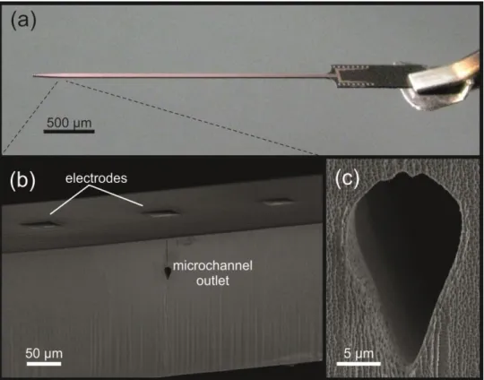
28
Fig. 1.9. (a) Photograph of a silicon-based neural probe for simultaneous in vivo electrophysiological recordings and drug delivery, microfabricated at the MFA. (b) Scanning electron microscopic image of the shaft section with electrodes on the front side and a microchannel outlet on the sidewall. (c) The profile of the microchannel.
The combination of CED with extracellular neural MEAs might open new possibilities in medical science, such as automated epileptic seizure detection and antiepileptic drug injection (Stein et al., 2000). MEMS technology makes possible the construction of neural implants with integrated fluidic ports and electrodes within the same probe shaft. A pioneering device of this sort was realized with anisotropic wet chemical etching of silicon (Chen et al., 1997) and was followed by several others (Liwei and Pisano, 1999; Papageorgiou et al., 2006; Retterer et al., 2004; Seidl et al., 2010). Fig. 1.9. shows images of a MEA with integrated microfluidic channels, developed at the Department of Microtechnology, MFA (Pongrácz et al., 2013).
29
Similarly to the silicon-based probes, the polymer-based devices can be equipped with channels, too (Metz et al., 2004).
Waveguides for optogenetics
Optogenetics is a technique based on the utilization of genetic modifications of cells in specific brain areas so that they express proteins that are light-sensitive. It allows neuroscientists to control neural activity with high spatial and temporal resolution. Genes encoding proteins such as channelrhodopsin, halorhodopsin and archaeorodopsin are available for such purposes (Boyden et al., 2005; Gradinaru et al., 2010; Han et al., 2011). To address the need of precise control of illumination with a microfabricated probe, the integration of waveguides onto silicon-based MEAs was solved recently (Wu et al., 2013). A polymer-based device was also constructed, combining electrode arrays with both drug and light delivery capabilities (Rubehn et al., 2011).
High surface area, low impedance microelectrodes
For the reasons presented in section 1.2.3. Roughness factor, electrodes with large effective surface area, related to their geometric area are preferred. Several porous materials, with huge roughness factor have been developed for this purpose. Early methods for thus minimizing impedance values of neural electrodes were performed by electroplating platinum, e.g. in Kohlrausch's solution (3% PtCl2 and 0.025% PbAc dissolved in 0.025N HCl) (Robinson, 1968). Recent studies involved diverse materials, such as carbon nanotubes (Baranauskas et al., 2011; Green et al., 2008b; Minnikanti et al., 2010) conducting polymers (Green et al., 2008a), polypyrrole/graphene oxide (Deng et al., 2011) and polypyrrole/carbon nanotube composites (Lu et al., 2010).
30
Fig. 1.10. (a) Fine wire tetrode. (b) A tetrode with low-impedance, electrochemically deposited gold electrodes (Ferguson et al., 2009).
Platinized platinum (Pt/Pt), due to its relatively simple deposition procedure and high roughness factor, would be an excellent candidate for large surface area coatings, but its mechanical stability is claimed to be poor (Desai et al., 2010; Heim et al., 2012b). Durability can be enhanced with the application of lead acetate (Robinson, 1968), the thus yielded deposit is usually referred to as Pt black. However, lead can be dissolved from the surface of the deposit, its application in implantable biosensors is hazardous (while electroplated Pt itself is non-toxic (Dymond et al., 1970)). Another approach to solve this problem is platinization with simultaneous ultrasonic agitation (sonicoplating) (Desai et al., 2010; Marrese, 1987). A review on various fabrication methods of porous platinum surfaces has been published (Kloke et al., 2011). These surfaces are applied in other microdevices besides neural electrodes, like pH (Noh et al., 2011) and glucose (Yuan et al., 2005) sensors.
In spite of the broad spectrum of the already published methods, impedance reduction of electrodes of neural MEAs is still an issue under active research.
31
2. SPECIFIC AIMS
2.1. In vivo recordings with silicon-based probes of extreme shaft length
Previous studies have confirmed that the shaft length of silicon-based probes, manufactured using standard MEMS technology can be increased from the common millimeter scale to a much greater one, up to several centimeters. However, in order to maintain mechanical robustness, it is beneficial if the cross-sectional dimensions of such extremely long probes are also increased (Fekete et al., 2013). We created probes with length of 1.5-7 cm and thickness and width of 200-400 µm, suitable for the penetration of the meninges (including the dura mater) and precise targeting. The scope of our experiments was to investigate the functionality of such devices during acute in vivo experiments, including their suitability for unit activity detection. The electrode arrays were tested within rat neocortex, hippocampus and thalamus.
2.2. Testing in vivo durability of platinized platinum electrodes
As described in section 1.3.4. Microelectrode arrays with special features, low impedance electrodes can be created with high surface area deposits. A factor that has to be considered is whether these materials are durable enough to withstand direct interfacing with the neural tissue. As their manufacturing cost is still relatively high, electrode arrays are not disposable, they are usually used multiple times for acute in vivo measurements. According to the current catalog of Neuronexus Technologies Inc.
(Ann Arbor, MI, USA), electrodes are reusable up to 15 times, if properly cleaned. The surface modification of electrode sites with coatings that repeatedly endure implantation and cleaning is not trivial.
32
In the chapters corresponding to this study, a Pt/Pt deposition procedure will be presented, created on a silicon-based extracellular MEA. The platinization method was developed with the variation of deposition parameters and applying ultrasonic treatment on the deposited layers afterwards. Parameters such as roughness factor, durability and controllability of the deposition were in our primary attention. The Pt/Pt deposits were tested with multiple acute in vivo experiments for durability and compatibility with acute stereotactic operation procedures.
2.3. Development and characterization of polymer-based microelectrode arrays with protruding sensor sites
As discussed in section 1.3.3. Polymer-based devices, polymer-based MEAs are frequently used for ECoG. In this case, the electrodes are placed onto the surface of the brain tissue. Furthermore, they are also utilized as intracerebral implants, in which case they function as extracellular MEAs. We aimed to create and test a construction between these two variations: a row of electrodes with protruding sites, which can slightly penetrate into the tissue and record signals from below the surface of the brain.
Fig. 2.1. Conceptual illustration of three different electrode array types.
Our goal was to develop a novel polymer-based MEA, with protruding sensor sites and perform proof of concept characterization.
33
2.4. Development and characterization of a multimodal, polymer-based microelectrode system
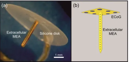
We intended to create an all-flexible version of the ―thumbtack‖ neural MEA, which had been successfully used for recording field potentials, multiple unit and SUA in behaving and anaesthetized humans (Ulbert et al., 2001). The preceding sensor contains a laminar array of polyimide isolated platinum–iridium electrodes on a single shaft with an outer diameter of 350 µm and length of 3 mm, which can be implanted into the cerebral cortex perpendicularly to the surface of the brain. The shaft perpendicularly protrudes out of the center of a silicone disk, which has a diameter of 8 mm. The disk facilitates the immobility of the shaft during recordings by plying to the brain surface. We aimed to modify this device by equipping the disk with an electrode array as well, thus making possible ECoG recordings in the vicinity of the implanted shaft. At the same time, we substituted the hand-made shaft with a polymer-based MEMS component in order to achieve a more precise and reproducible manner of fabrication and fine mechanical coupling between the probe and the tissue. The ECoG component was designed to be equipped with eight relatively large circular sites (d = 200 µm) for field potential recordings. The extracellular MEAs were designed to contain smaller electrodes (d = 30 µm), which might be suitable for the detection of action potentials of individual neurons within the tissue.
Fig. 2.2. (a) The thumbtack microelectrode array (www.plexon.com) (b) Conceptual illustration of the multimodal, polymer-based microelectrode system
34
3. METHODS
3.1. Methods related to in vivo recordings with silicon-based probes of extreme shaft length
3.1.1. Design and fabrication
Shaft thicknesses were defined by the substrate silicon wafers (200 μm and 380 μm), while their widths and lengths could be freely varied: 206 μm and 400 μm wide shafts with four different lengths (15 mm, 30 mm, 50 mm and 70 mm) were designed.
These parameters have been thoroughly combined.
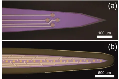
The electrodes (recording sites) on the probe tip were arranged as tetrodes (4 electrodes per probe in rhombus vertices) and linear arrays (12 or 16 sites in the midline of the front side of the shaft). Considering the latter, center-to-center distances of the 30 μm × 30 μm and 50 μm × 50 μm recording areas were 100 μm and 200 μm, respectively.
Fig. 3.1. (a) Tetrode and (b) linear electrode array configurations.
35
Tetrodes were optimized for measuring SUAs, therefore they were more compactly designed: the octagonal sites, 22 μm in diagonal, were located 46 μm distant from each other. Microscopic images, presenting different electrode arrangements are shown in Fig. 3.2.
The fabrication technology of the MEAs is based on a single-side, three mask bulk micromachining process sequence that proceeded in three phases. Schematic cross- sectional view of the probe during the fabrication process is shown in Fig. 3.2. 200 μm and 400 μm thick, double-side polished (100) oriented 4-inch silicon wafers were used for the probe fabrication. The initial phase consisted of thin-film depositions to form the bottom insulating layers, the electrodes and output leads (Fig. 3.2 (a)). In the second phase the upper passivation layers were deposited and the contact holes, bonding pads and contour of the probe body were formed by different etching steps (Fig. 3.2 (b)). In the last phase, DRIE was used to define the probe shafts and bases (Fig.3.2 (c)) followed by the removal of the different masking layers and packaging of the probe.
Fig. 3.2. Technological processes. (a) Forming lower insulator and patterned metal layers, (b) upper insulator layers, opened at the sites, (c) silicon dry etching with Bosch process.
36
Contact formation was carried out as follows. In the first step 500 nm thick SiO2
layer was thermally grown on both sides of the wafer, followed by a deposition of 300 nm thick low-pressure chemical vacuum deposited (LPCVD) low stress silicon-nitride.
The metal layer was then deposited and patterned by lift-off process. The lift-off structure composed of 1.8 μm thick photoresist (Microposit 1818) layer over patterned Al thin film of 500 nm. The metal layer consisted of a 15 nm thick adhesion layer of TiOx and Pt. TiOx was formed by reactive sputtering of Ti in O2 (Ar/O2 ratio was 80:20) atmosphere. In the same vacuum cycle 270 nm thick Pt was sputtered on top of TiOx. The lift-off was accomplished by dissolving the photoresist pattern in acetone, this process was optimized by using water-cooled substrate holder which diminished the resist distortion during TiOx/Pt sputtering. Subsequently, the removal of Al patterns in four component etching solution and low pressure chemical vapor deposition of 300 + 300 nm thick SiNx/SiO2 insulating layer stack occurred. Contact holes through the insulating layers were created by selective wet etching processes. By these processing steps, Pt lines insulated by SiNx/SiO2 layers and formation of Pt contacts have been carried out.
Fig. 3.3. (a) 16-channel multielectrodes on a micromachined silicon wafer.
(b) A packaged silicon-based neural electrode on a PCB with shaft length of 3 cm
For probe shaping, a 500 nm thick Al layer was deposited on the front side and patterned by photolithography using 4 μm thick SPR220 photoresist. The body of the probe was defined by Al wet etching. SPR220 photoresist was spun also on the backside of the wafer used as a stopping layer during the subsequent DRIE of silicon. The 3D
37
micromachining process was performed in an Oxford Plasmalab System 100 chamber using Bosch process.
The probes were flipped out of the wafer and glued onto a printed circuit board (PCB) with a two-component epoxy resin (Araldit AY103/HY956). 50 μm thick Al wires have been employed to establish connection between the bonding pads and the PCB leads using a Kulicke-Soffa ultrasonic wire bonder. For the insulation and protection of the Al wires, the same resin has been used as for the gluing. Fig. 3.3.
shows images of the MEAs during and after fabrication.
3.1.2. In vivo measurements
The MEAs were tested on Wistar rats (n=4) in the Institute of Cognitive Neuroscience and Psychology of the RCNS-HAS. Animal care and experiments were performed in compliance with Animal Care Regulations of the Institute of Cognitive Neuroscience and Psychology of the Hungarian Academy of Sciences and order 243/1988 of the Hungarian Government, which is an adaptation of directive 86/609/EGK of the European Committee Council. The animals were initially anesthetized via intraperitoneal injection of a mixture of 37.5 mg/ml ketamine and 5 mg/ml xylazine at 0.3 ml/100 g body weight injection volume. The sleeping state was maintained by intramuscular updates of the same solution (0.3 ml / hour). A drop of paraffin oil was applied in each eye in order to prevent them from drying. The body temperature was maintained at 37 °C with an electric heating pad. The animals were mounted in a stereotactic frame (David Kopf Instruments, Tujunga, CA, USA), restraining their heads. After shaving the scalp, it was incised in order to gain access to the skull. Soft tissues, including the periosteum covering the skull were removed with a scalpel. The bone was cleaned with 1% hyperol solution (Meditop Ltd., Pilisborosjenő, Hungary). The animal preparation procedures described hitherto were the same for other in vivo operations presented in this dissertation.
Crainotomy window was opened from -1 mm to -5 mm anteroposterior (AP), from 1 mm to 4 mm mediolateral (ML) in reference to the bregma. Each probe, attached to the micromanipulator arm of the stereotactic device was slowly inserted into the
38
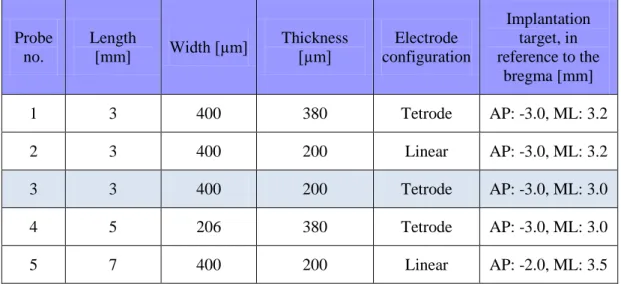
cerebrum of an animal without removing or incising the dura mater. Stereotactic coordinates of the targets are presented in table 3.1.
Probe no.
Length
[mm] Width [µm] Thickness
[µm] Electrode configuration
Implantation target, in reference to the
bregma [mm]
1 3 400 380 Tetrode AP: -3.0, ML: 3.2
2 3 400 200 Linear AP: -3.0, ML: 3.2
3 3 400 200 Tetrode AP: -3.0, ML: 3.0
4 5 206 380 Tetrode AP: -3.0, ML: 3.0
5 7 400 200 Linear AP: -2.0, ML: 3.5
Table 3.1. The main properties of the MEAs, functionally tested in vivo.
Measurements performed with probe no. 3 are presented in details later.
Probe no. 3 and 5 were implanted into the same animal, at different stereotactic coordinates.
3.1.3. Signal acquisition and data processing
Signals were recorded using a two-stage amplifier and a data acquisition system with a gain of 1000, 20 kHz sampling rate and 16 bit resolution (LabView, National Instruments Corp., Austin, TX, USA). Edit 4.5 software of Neuroscan (Charlotte, NC, USA) was used for off-line signal visualization, filtering and analysis. The Klusters free software was used for clustering unit activities (Hazan et al., 2006), which is currently (on October 15, 2014) available for free download from the website http://neurosuite.sourceforge.net/
39
3.2. Methods related to in vivo durability tests of platinized platinum electrodes
3.2.1. Silicon probes
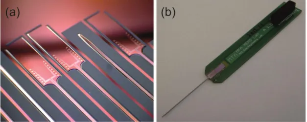
The manufacturing technology and in vivo characterization of the probes employed for these experiments were described in detail by Grand et al. (Grand et al., 2011). In the midline of the single, 7 mm long, 280 µm wide, 80 µm thick probe shaft 24 sputter-deposited platinum electrodes had been manufactured with geometric areas of 30 µm × 30 µm. Fig. 3.4. shows microscopic images of such a device.
Fig. 3.4. (a) 7 mm long, 280 µm wide, 70 µm thick, 24-channel silicon- based neural probe with a pointed tip on a PCB. (b) The tip of the probe shaft.
40
3.2.2. Basic electrochemical measurements
Electrochemical impedance spectroscopy
Electrochemical impedance spectroscopy (EIS) measurements were performed in lactated Ringer’s solution (Teva Pharmaceutical Industries Ltd., Israel), using an Ag/AgCl reference electrode (Radelkis Ltd., Hungary) and a counter electrode of platinum wire with relatively high surface area. The probe signal was sinusoidal, 25 mV RMS. A Reference 600 instrument (Gamry Instruments, PA, USA) was used as potentiostat and Gamry Framework 6.02 and Echem Analyst 6.02 software were used for experimental control, data collection and analysis. Experiments were performed in a Faraday cage.
Cyclic voltammetry
Cyclic voltammetry (CV) allowed sensitive measurements of the surface area of the electrodes. Curves were obtained with a PAR 283 potentiostat, in a three compartment electrochemical cell. 0.5 M H2SO4 solution has been deoxygenated with argon of 99.9995 purity and was used as electrolyte, isolated from air. A hydrogen electrode and a platinum sheet were used as reference and counter electrodes, respectively. The real surface areas of the recording sites were computed from the CV curves (Woods, 1976) and by dividing these data with their projected footprint area (geometric surface area), the roughness factor of the electrodes were determined.
3.2.3. Electrolytic deposition of platinum
In order to obtain electrodes with large effective surface area, Pt/Pt layers were electrochemically deposited using a PAR 283 potentiostat and a solution of 1 g PtCl4 × 2HCl × 6 H2O + 2 cm3 conc. HCl + 200 cm3 H2O. Potentiostatic rather than galvanostatic deposition was chosen, since it yields a more controllable process and a more homogenous deposit. Parameters such as potential and time have been set to 100 mV (vs. reversible hydrogen electrode) and 10 minutes, respectively. During preliminary experiments, several other depositing parameters were also tested before
41
these were chosen. During these tests the roughness factor of the deposits as well as their durability against ultrasonic bath were kept in focus.
The 24-channel MEAs have been modified the following way. Platinum was electrochemically deposited onto every second (2nd, 4th, etc.) channel simultaneously using the above described plating method, while odd-numbered (1st, 3rd, etc.) channels were only immersed in the plating solution and no voltage was applied on them (these sites were used as controls in this study). Odd-numbered and even-numbered channels will be referred to as thin-film Pt and Pt/Pt electrodes, respectively.
The Pt/Pt structures were analyzed with optical microscopy and SEM. Focused ion beam (FIB) method with Ga ions accelerated to 30 keV was used to cut the Pt/Pt deposits in order to have cross-sectional view of them. SEM images of thin-film Pt and Pt/Pt electrodes are shown in Fig. 3.5. These images reveal that the electrochemically deposited Pt layer is thicker at the edges of the electrodes.
Fig. 3.5. (a) Scanning electron microscopic images of four neighboring electrode sites on the MEA, two of them coated with Pt/Pt. (b) A cross- sectional view of the Pt/Pt layer, sectioned with Focused Ion Beam (FIB).
Pt1 is the original thin-film layer, Pt2 is electrochemically deposited. (c) The surface of a platinum deposit (Pt/Pt electrode).