Mobil robot localization using RGB-D camera
László Somlyai
Óbuda University, Doctoral School of Applied Informatics, Hungary somlyai.laszlo@nik.uni-obuda.hu
Abstract—The paper shows a movement tracking and a map building system based on a RGB-D camera for mobile robots.
With the data of the Kinect sensor the system estimate the displacement of the sensor. It uses only the color and pixel- level depth informations of the camera. Beside the estimation of displacement the three dimensional map of the environment is obtainable known the movement of the sensor. This information can be used by the navigation algorithm of the robot during its mission.
The paper describe the operation of the process which based on the measuring of sensor displacement. Value of displacement is based on the join of the three dimensional point clouds of the environment. The point clouds made in different time and place can be overlapped in a manner. Searching of the overlapped feature points happens with the SURF feature detector. The transformation among the smaller set of points (how much moved the sensor in the space during the measurement) is given by the ICP algorithm. The joining happens in several steps, during this the erroneously detected point pairs are eliminated. In this way more accurate results are available.
I. INTRODUCTION
The recently published relatively cheap and small RGB-D sensors (Kinect, Asus Xtion, PrimeSense ...) can be found in more and more robot development. It has simple construction but it is suitable for sensing a mobile robot environment.
Control of a robot the main task is to the system build a map with the help of the sensor data and define its position in a given environment.
Az "RGB-D Mapping - Using Depth Cameras for Dense 3D Modeling of Indoor Environments" [1] text deals with the three dimensional mapping of the inside environment. RGB-D camera is used for the mapping. It is built on the PrimeSense sensor which is very similar to the Kinect. The system makes the three dimensional image of the environment from the sensor data where it marks feature points. Searching of the features happens with the SIFT feature detector. For joining of the point clouds a RGBD-ICP algorithm was developed.
Finally the position of the vehicle is refined by searching closed loops in the global map.
The a "Visual Odometry and Mapping for Autonomous Flight Using an RGB-D Camera" [2] project uses the detection system shown in the previous work. It presents a process where control the air plane with the data of a RGB-D camera.
Searching of the feature points happens with the FAST feature point detector. For the valuation of the initial displacement inertial system (IMU) is used. The system refines the joining of the system with minimalization of summarizing the square pixel error.
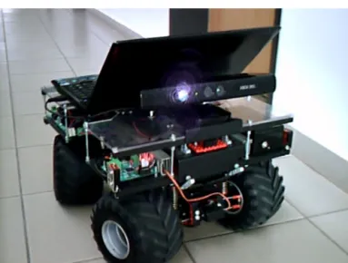
Fig. 1. Our robot car, with Kinect sensor
An other paper [3] deals with the three dimensional reconstruction of the environment with RGB-D camera. Low- cost camera used which gives color and pixel-level depth information about the area in front of the air plane. Movement of the camera can be followed in this virtual environment.
The "Using the Kinect as a Navigation Sensor for Mobile Robotics" [4] article uses the data of the Kinect sensor as a three dimensional point cloud and a two dimensional projection as well. These source of data are used for localization and map builder. The developed method is compared to the currently used SLAM processes.
A fuzzy-based path finding robot [5] plans the route based on the data of the Kinect sensor in a local map.
The two dimensional local map originates from the current measurement of the sensor [6]. In the inside navigation the most used sensors are the RGB-D camera, LIDAR and the inertial unit (IMU).
II. ROBOT NAVIGATION
An autonomous mobile robot performs a specified task during its mission. Necessary to know the current position and the coordination of the target. Its should be detect the obstacles. This time there are two possibilities: the robot knows the map of the environment where the mission is performed. In this case localization can happen in the available map. Another case is the robot navigates in an unknown environment, during this mission space qualification is also
necessary. It defines the position and the coordination of the target in the map built up during the mission.
The global navigation systems are not suitable in indoor, for example GPS system. One of the positioning possibilities is recognizing feature objects. With the help of a camera and feature points are tried to be recognise to define the current position. The base of one navigation is feature points (example: QR-code) are placed which accurate position is known. It watches the points with a camera and determine its own position.
For storing robots a line is painted between the starting point and the target. It following the line until the goal. The line can be painted up or a signal line is placed in the ground what the system follows.
The disadvantage of these that infrastructure is needed.
Indoor the inertial navigation system can be used which estimate the movement of the robot. The measurement is refereed to the acceleration measurements. Its disadvantage is the position of the robot is more inaccurate because of the accumulated errors.
In a previous paper we show a robot vehicle (Figure 1) where the localization and map building happened by only the data of the displacement sensors. The main disadvantage of this that the measurement faults are accumulating continuously on the path of the robot. Now this system is completed by the Kinect sensor which uses visual elements as well.
Between two sequential measurement of the RGB-D camera can be estimate the movement of this sensor. The system uses only the color and pixel-level depth image of the camera for following the movement. Definition of movement is based on the join of point clouds made during each measurements. In this system measurement faults also accumulate to each other, so the position of the sensor becomes more inaccurate and the position of the robot as well. If the robot goes back to a place earlier discovered and it knows this, the accuracy of localization will be increasable.
III. RGB-DCAMERA
The Kinect (Figure 1) is a RGB-D sensor which was developed for controlling games [7] not necessary to uses joystick, keyboard, mouse for this. The RGB-D camera gives color image and pixel level depth informations about the area located in front of it. Using this information three dimensional virtual picture of the environment can built up. The Kinect sensor project a dot net and the distance of the object is calculated from its differences.
Earlier I made the accuracy-distance functions of the sensor.
In case of the objects closer than 1m the standard deviation of measurement is only 4 − 5mm, but until the further measurements it reached the 20mm. The measurement fault was reduced to3mmby a special averaging filter. Few meters of sensing range of the sensor and its accuracy in the province makes it suitable to use it on smaller mobile robots but only for indoor using [8].
After calibration of the depth sensor the real coordination of one pixel of the depth picture[ud, vd]T can be calculated in the
coordinate system of the depth camerapni ∈Xn(1). TheXn
set is the point cloud of thenthmeasurement in the coordinate system of the depth camera. In my application the coordinate system of the depth camera is equal to the coordinate system of the sensor.
p= [px, py, pz]T =
(ud−pdx)∗δ(ud, vd)/fdx
(vd−pdy)∗δ(ud, vd)/fdy
δ(ud, vd)
(1) ,where fd = [fdx, fdy] is focal length of camera and pd = [pdx, pdy] is principal point of camera and δ(ud, vd) is the real distance.
The color camera is 640x480 resolution and it gives 24 bit color image when the refresh rate is 30f ps. Between the two cameras the Equation 2 makes connection, where the τcd = {Tcd, Rcd} is the transformation between the coordination systems of the cameras.
[u0c, vc0]T =
fcx 0 0 0 fcy 0
∗p0/p0z+cc (2) ,where p0 =Rcd∗p+Tcd,fc = [fcx, fcy] is focal length of camera andpc= [pcx, pcy]is principal point of camera.
Fig. 2. Left image: color and depth data of Kinect sensor. Middle image:
three dimensional point cloud. Right image: two dimensional map projected from the point cloud
IV. FEATURE DETECTOR
Measurements are made continuously by the Kinect sensor during the system operation. One paper shows a method for the thermal image matching [9]. The measurement made by the current environment of the sensor gives a three dimensional point cloud which is in the Xn set. The Xn+1 set is result of the next measurement. Results of the measurements can be transformed into a global space (W) by definition of displacement among the point clouds. TheW set is the part of the world coordinate system which gives the reference point.
Matching of point clouds can happen in two ways. In the first case displacement is defined among the earlier point cloud and the later. In this way the latest measurement is adding to the global map, the measurement faults are accumulated greatly.
In the other case the results of later measurements are joined to the global point cloud. In this way there are less measurement faults besides if we go back to the area travelled earlier, we are able to know the position of the robot accurately.
The first estimation of displacement among the measurements is given from the sensors which was used in the earlier work as well. In case of the incremental sensors
only the movement of the robot on flat surface can be followed.
We have to know the same three dimensional points in both sets. These feature points are stored in the global map. Many feature point searching algorithm exist. These are different in their operation and speed. Some known feature point detectors are the SIFT [10], SURF [11], KLT [12].
The feature point detectors respond in different ways to the different images. From the SIFT, PCA-SIFT and SURF feature detector the SIFT detector gives the best result for the scaling, rotating transformation and for blur [13]. A main disadvantage of SIFT detector is the running time of the algorithm at the issues of mobile robots. The fast feature detection is necessary for the real time mapping, that is why I chose the SURF method which is much faster but it gives worse result slightly.
The plane feature point [uc, vc]T founded in the color camera image must be transformed into the coordinate system of the depth camera (3). Case of the simple RGB-D camera the Tinv transformation can not be determined clearly.
[px, py, pz]T =Tinv∗[uc, vc]T (3) During the transformation of depth camera pixels the algorithm examine the point is feature or not. It searches the nearest pixels to every feature point in the depth camera point.
The nearest picture point is defined by Euclid distance. The points have worse result are not considered as feature point by the algorithm at a thmax distance. Feature point founded are in theFn set. Which include the descriptive feature vector, the coordinate of the point and the three dimensional coordinate of the point.
V. 3DMAPPING
The main task is define a transformation among the point cloud from the current measurement and the reference points of the system during map construction. For this the algorithm select same feature points from the points of the current and earlier measurements. The earlier measurement D and the suited (new) S feature set include the list of corresponding points.
Join of feature pairs happens by the ICP algorithm. The ICP [14] algorithm gives the transformation among the two sets, with this the join fault of the two sets will be minimal. Usually it is used at two and three dimensional set of points. The ICP algorithm needs a initial transformation.
The simple ICP algorithm searches the nearest point in the other set with the help of the current transformation. With this point pair it modifies the transformation among two sets. In this way the fault of the two sets will be minimal.
Running of the ICP algorithm happens between the earlier and actual point pairs in my application. Advantage of this that the iteration of the algorithm decreases significantly because the algorithm counts only with a few specified points.
The join can be more accurate if the ICP algorithm is ran on those sets where every points have a real pair. The erroneously detected point pairs are deleted from the list of sets. The
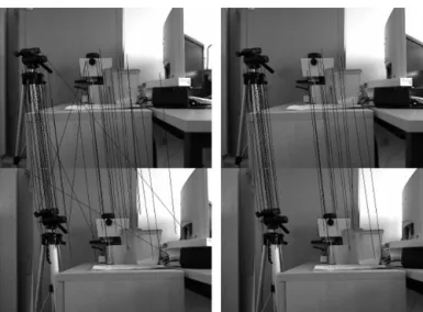
Fig. 3. Result of feature points search. Left image: result of SURF detector, 52 piece of feature pairs. Right image: the remaining 39 piece of feature pairs after matching algorithm.
Algorithm 1 Multistage three dimensional point cloud matcher
T =T0
en=estart
forj= 0→maxIteraciodo T=ICP(D,S,T);
fori= 1→ |D|do S0=T∗S if q2
(dix−s0i
x)2+ (diy −s0i
y)2+ (diz−s0i
z)2 > en
then
remove(di, si) end if
end for
ifemax> en then end algorithm else
en = en/2 end if end for
faulty point pairs originates from the erroneous detection of the feature point detector.
For the determining transformation among feature points I used a multistage join method. In iterations the ICP algorithm gives the transformation among sets. The algorithm originates from an T0 initial transformation, which may come from a displacement sensor or an IMU. Now the ICP algorithm gives this initial transformation.
During the iterations the algorithm deletes those points which Euclid distance is more than en with the help of the current transformation. The en is the maximum difference between the joined points in a iteration. Its initial value the estart and theemax gives the required value of the join fault.
In the first step the algorithm filters out those feature pairs which have higher error. The en gives lower value in every
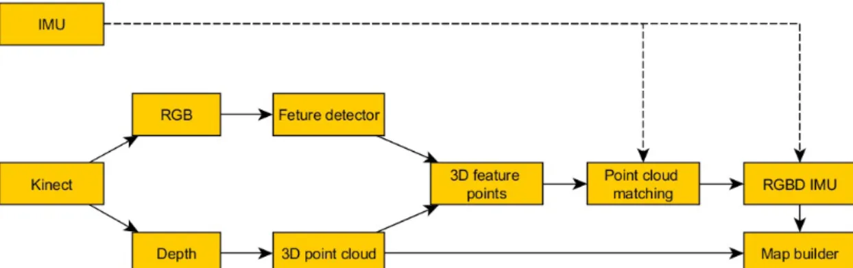
Fig. 4. Scheme of the map builder
iteration because better quality feature pairs are available for the ICP algorithm. In this way more accurate transformation (T)is defined among the sets.
The algorithm stops when the iterations reaches a maximum iteration number(maxIteracio), or the required accuracy of the matching is reached (emax). The block diagram of the sensor follower and map building system is summarized on the Figure 4.
The join method described is searching for the feature pairs on the sequential images. With the help of these the later measurements are matched into the global point cloud. The algorithm can be more accurate if the feature points are stored in the global point cloud.
During the navigation the three dimensional point cloud can project to a two dimensional map (Figure 2). Only the obstacles shown on the level of the robot in the map. The standard path founding algorithms (wave propagation, A* ...) be able to used in this simplified map for the navigation.
Another way for using the system is to use only the displacement data. The accumulated value of primary displacement defined during the measurements gives the position of the sensor compared to the switch-on point. Such use we get an IMU unit which is based on visual elements (RGBD-IMU).
VI. RESULTS
Testing of the algorithm happened in two steps. First of all I examined the answer of the sensor for the translational movement. Measurement of the real and estimate displacement of the sensor happened in more points along the x axis (Table I). The sensor moved along the x axis only, the y and z movement was 0mm. Value of the rolls around the axis (φ,Θ, ψ) was 0rad as well. Average fault of matching is defined by the Euclid distance (4). The fault was defined among every matched feature pair.
e= 1
|D|
|D|
X
i
2
q(Dix−Si0
x)2+ (Diy −Si0
y)2+ (Diz −Si0
z)2 (4) ,where S0=T∗S.
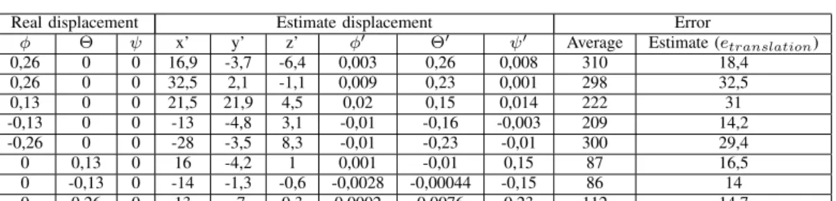
The fault of displacement is given by the Euclid distance (5), where x, y, z is the real displacement and x0, y0, z0 is the estimate displacement. Rotation movement of the sensor happened around one point (Table II), where the real rotation φ,Θ, ψ and the estimated rotation φ0,Θ0, ψ0 were compared.
etranslation=p2
(x−x0)2+ (y−y0)2+ (z−z0)2 (5) Finally the result of a sequence containing more than one measurement can be seen in the Figure 5. In the sequence results of 30 measurements were matched during rotation of the sensor in 180 degrees. Finally the translational fault of the matching wasetranslation= 135mm.
VII. CONCLUSION
Spatial displacement of the sensor can be measured relatively high accuracy by the data of the Kinect sensor.
Condition of measurement of the displacement is to be sufficient overlap among the measurements. The feature point searching algorithm has to find a sufficient number of point pairs on the overlapped area. Beside the data of the sensor using inertial sensor can refine and speed up the measurement [15].
In the paper an own matching algorithm was presented which processes only the data of a RGB-D camera. For the improvement of accuracy of matching multistage matching process is used.
ACKNOWLEDGMENT
The author(s) gratefully acknowledge the grant provided by the project TÁMOP-4.2.1/B-11/2/KMR-2011-0001.
REFERENCES
[1] P. Henry, M. Krainin, E. Herbst, X. Ren, and D. Fox.,RGB-D Mapping:
Using Depth Cameras for Dense 3D Modeling of Indoor Environments Proc. of the International Symposium on Experimental Robotics (ISER), 2010
[2] A. Huang , A. Bachrach , P. Henry , M. Krainin , D. Maturana , D. Fox , N. Roy,Visual Odometry and Mapping for Autonomous Flight Using an RGB-D Camera Int. Symposium on Robotics Research (ISRR), 2011 [3] Hao Du, Peter Henry, Xiaofeng Ren, Marvin Cheng, Dan B Goldman,
Steven M. Seitz, Dieter Fox, Interactive 3D Modeling of Indoor Environments with a Consumer Depth Camera Proceedings of the 13th international conference on Ubiquitous computing (UbiComp ’11), pp. 75-84, ISBN: 978-1-4503-0630-0, Beijing, China, 2011
Real displacement Estimate displacement Error
x y z x’ y’ z’ φ0 Θ0 ψ0 Average Estimate (etranslation)
100 0 0 98,4 5,2 0,2 0,005 0,003 0,001 108 5,4
50 0 0 49,1 1,7 -1,3 0,003 0,004 -0,003 62 2,3
100 0 0 104,3 4,1 1,8 0,005 -0,0008 -0,000095 111 6,2
120 0 0 109,1 -0,13 0,48 -0,00003 0,011 0,0084 125 4,8
TABLE I
RESULTS OF MEASUREMENT. SENSOR ACCURACY OF TRANSLATION MOVEMENT.
Real displacement Estimate displacement Error
φ Θ ψ x’ y’ z’ φ0 Θ0 ψ0 Average Estimate (etranslation)
0,26 0 0 16,9 -3,7 -6,4 0,003 0,26 0,008 310 18,4
0,26 0 0 32,5 2,1 -1,1 0,009 0,23 0,001 298 32,5
0,13 0 0 21,5 21,9 4,5 0,02 0,15 0,014 222 31
-0,13 0 0 -13 -4,8 3,1 -0,01 -0,16 -0,003 209 14,2
-0,26 0 0 -28 -3,5 8,3 -0,01 -0,23 -0,01 300 29,4
0 0,13 0 16 -4,2 1 0,001 -0,01 0,15 87 16,5
0 -0,13 0 -14 -1,3 -0,6 -0,0028 -0,00044 -0,15 86 14
0 0,26 0 13 -7 0,3 0,0002 0,0076 0,23 112 14,7
TABLE II
RESULTS OF MEASUREMENT. SENSOR ACCURACY OF ROTATION MOVEMENT.
Fig. 5. Reconstruction of the environment from 30 measurement.
[4] Ayrton Oliver, Steven Kang,Using the Kinect as a Navigation Sensor for Mobile Robotics IVCNZ 2012, pp. 509-514 , ACM: 978-1-4503-1473-2, Dunedin, New Zealand, 2012
[5] György Csaba, Zoltán Vámossy, Fuzzy based obstacle avoidance for mobil robots with Kinect sensor 4th IEEE International Symposium on Logistics and Industrial Informatics (LINDI),pp.135-144, ISBN: 978-1- 4673-4520-0, doi: 10.1109/LINDI.2012.6319476, 2012.
[6] Molnár A. Optikai d˝olésmérésen alapuló repülésstabilizálás Repüléstudományi konferencia, 2009 50 év hangsebesség felett a magyar légtérben, 2009. április 24, Szolnok
[7] Microsoft Kinect SDK,
http://research.microsoft.com/en-us/um/redmond/projects/kinectsdk/
(Visited: 2011. jan. 21.)
[8] László Somlyai, Zoltán Vámossy, Map Building with RGB-D Camera for Mobil Robot IEEE 16th International Conference on Intelligent
Engineering Systems 2012 (INES 2012), pp. 489-493, ISBN: 978-1-4673- 2695-7, Lisbon, Portugal, 2012
[9] Vamossy, Z.Thermal image fusion Intelligent Systems and Informatics (SISY), 2012 IEEE 10th Jubilee International Symposium on, pp. 385- 388, E-ISBN: 978-1-4673-4749-5, DOI: 10.1109/SISY.2012.6339549, Subotica, 2012
[10] David G. Lowe, Distinctive image features from scale-invariant keypoints International Journal of Computer Vision, pp. 9-110, 2004 [11] Herbert Bay, Andreas Ess, Speeded-UpRobustFeatures (SURF)
Computer Vision and Image Understanding, Vol. 110, Issue 3, pp. 346–359, 2008
[12] B. D. Lucas and T. Kanade,An iterative image registration technique with an application in stereo vision in Seventh International Joint Conference on Artificial Intelligence (IJCAI-81), pp. 674-679, 1981 [13] Luo Juan, Oubong Gwun,A Comparison of SIFT, PCA-SIFT and SURF
International Journal of Image Processing (IJIP), Vol. 3, Issue 4, pp. 143- 152, 2010
[14] S. Seeger, X. Laboureux, G. Hgausler,An Accelerated ICP-Algorithm Optical Sensing, Metrology and INspection, Annual Report, pp. 32, 2001 [15] Molnár A., Stojcsics D.New approach of the navigation control of small size UAVs Proceedings of 19th International Workshop on Robotics in Alpe-Adria-Danube Region, pp. 125-129., IEEE Catalog Number:
CFP1075J-CDR, ISBN: 978-1-4244-6884-3, Budapest, Hungary, 2010