Differences Between Kinect and Structured Lighting Sensor in Robot Navigation
György Csaba*, László Somlyai**, Zoltán Vámossy***
Óbuda University, John von Neumann Faculty of Informatics, Hungary
*csaba.gyorgy@nik.uni-obuda.hu, **somlyai.laszlo@nik.uni-obuda.hu, ***vamossy.zoltan@nik.uni-obuda.hu
Abstract—Nowadays, autonomous navigation is getting more and more attention. The mobile robots need to have map of the close environment. The paper presents how can collect information about the environment for robot navigation. The sensors and the navigation system are installed on a mobile equipment platform. After this the article shows the different measurement systems, the generating virtual depth map and the navigation algorithm. At the end the Kinect sensor is compared with a sensor based on structured light.
I. INTRODUCTION
One of our previous paper shows how does the laser based structured light sensor work [1]. That paper presented the accuracy and working properties of this sensor. We accomplished a mobile robot navigation with this sensor information. Microsoft has developed and made available for an RGB-D sensor, which called Kinect, in December 2010.
The sensor uses a projected point mash and it gives some depth information. The navigation software can create a virtual depth map from the Kinect sensor data like the structured lighting sensor. The paper compares to the structured lighting sensor and the Kinect sensor data and analyzes the differences between these sensors, like the accuracy, measurement range and the processing time.
II. ROBOTVEHICLE
The sensor system has been built on an electronic radio controlled car. This vehicle has electronic gear drive, and front and rear wheels are steered by servo motors.
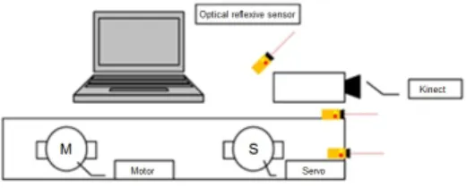
Fig. 1. The robot vehicle with Kinect sensor, control computer and embedded system.
This RC car includes the sensors, the embedded system and the control computer. The Figure 1 shows the robot vehicle. The robot has two embedded electronic systems for the vehicle controlling. First electronic system is the motor control unit which connects to the CAN bus of the vehicle.
The other controller is the CAN communication module. This module is the gateway between the PC USB port and the vehicle CAN bus. The detection of the objects happens on the main computer. The robot uses some sensors for the detection of the objects. These sensors are the Kinect sensor, or our structured lighting sensor which is implemented on the LEGO tower, and some opto-reflective sensor. First we implemented the Laser sensor [1] and later it was removed from the car, and implemented a new sensor, Kinect. This sensor gives the map information, similar as the previous sensor. From this information the car gets the necessary command for the navigating. The robot uses some industrial opto-reflective sensors for the sensing of the dead space of the camera (Fig 2).
Fig. 2. Robot car and the sensor system
III. STRUCTURED LIGHT
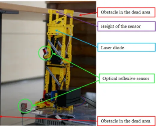
Our sensor system has two parts which were mounted a LEGO tower (Fig 3). First one is the 150 mW laser projector.
It is transformed to a line a dot shaped light of a laser diode by the optic. The other part is a Logitech V-UBM46 web camera which senses the laser light. The size of the sensor operation range depends on the camera field of view and the angle between the laser and the camera. If the angle between the camera and the laser is bigger, the sensing area will be bigger as well. In this case the accuracy of measurement will be worse. If the light of the laser is broken by an object, the laser light is located higher on the image of the camera.
The software can calculate the distance of the object from this information.
Fig. 3. Visual field of the structured lighting sensor. This sensor implemented a LEGO tower. It has some opto-reflective sensors. These sensors detect the obstacles at the top of the structured lighting sensor, which can not detect by the developed laser based sensor.
A. Laser detection
The task of the detection is to define the laser stripe in the picture while other disturbing elements are shown on the source picture. For example, this is possible by the following simple methods [1]:
• Laser detection based on color space. ([1] / IV.B.1.)
• Laser detection based on intensity. ([1] / IV.B.2.)
• Laser detection weighting method. ([1] / IV.B.3.)
• Laser detection based on edge detection. ([1] / IV.B.4.) With the combination of the previous methods described above we can get a better detection method. With the result of the weighting and intensity-based search only the high intensity and red-shaded pixels remains in the picture. This prevents the loss of information at the weighting method because of the burn-out pixels. In this case the detection contains many errors, therefore we execute a special type of canny edge detection in the source picture. The result of the two previous pictures in logical "and" connection is the desired excepted detection [1].
B. Depth map
A depth map is needed for the route planning. This is a two dimensional D[e, r] array, that shows the location of the objects. Each cells of the matrix represents some parts of the area in front of the vehicle. The map demonstrates well the distance between the vehicle and the objects, and also demonstrates the direction of objects. The distance of an object affects the accuracy of measurement, because the more further it is the smaller it is. With increasing of the distance one centimeter is illustrated by less and less pixels. In this way the accurate identification of the laser happens more and more doubtfully on the picture.
IV. KINECT SENSOR
The Kinect is a RGB-D sensor that the Microsoft developed for game controlling, end of year 2010 [2]. Its goal was the game controlling will be possible without joystick, keyboard or mouse. The human will be the controller. The RGB-D
sensors give a color image for the local area and join the depth information for this image. The local map of the nearly environment is built up from this depth information. And the software can join some color information for the object.
The RGB-D sensor projected a point mesh to the objects and a camera with infra filter sense this mesh and calculate the distances. Kinect is an active sensor. The active optical sensor can work without external light. But the color camera can not work without some light source. In this case the system gives just depth information. The color camera resolution is 640x480 and it is color resolution is 24 bit. Every color pixel has depth information. The depth sensor operation range is between 0,5 m and 4 m. The refresh rate of the color image and the depth information is 30 fps.
A. Real coordinates
The control software can calculate the real coordinates for the depth information. It uses the following equations (1), (2), (3).
rz(x, y) =z (1)
rx(x, rz(x, y)) = x
w−0,5 ∗rz∗XtoZ (2) ry(y, rz(x, y)) = 0,5−y
h ∗rz∗Y toZ (3) Where, z is the object distance, x is an x and y is an coordinate y of depth image, w is width and h is height of the depth image and XtoZ,Y toZ are a constant values.
And it can realize a three dimension data (Fig 4).
Fig. 4. Visualize the Kinect sensor depth data in 3D. This image shows a 3m2area, which has some objects.
The system knows the position and dimensions of vehicle in this space. It takes a slice from the environment in the y axis. The height of this slice is equal to the vehicle. Finally, this space will be screened in thexzsurface. In this case a two dimensional image is generated, like the previous chapter. This information gives, what object is obstacles in the area in front of the robot (Algorithm 1). The conversion function executed 20 millisecond in the test computer [ASUS UL30V, Intel Core 2 Duo 1,6 GHz].
Algorithm 1 Create depth map fori= 0→hdo
forj= 0→w do
if ry(y, rz(x, y)) < rm and ry(y, rz(x, y)) > rm then
D[rz(x, y), rx(x, rz(x, y))]
end if end for end for
V. COMPARISON OF THE SENSORS
Previously mentioned two types of sensors are also active sensors. The advantage of these sensors that can give correct depth data even when no light source is in the environment.
Both sensors measure the distance to a similar principle. The structured lighting sensor projects are only a one dimensional laser stripe so only a small part of the obstacles can be sensed.
In contrast the Kinect is projected a 2 dimensional point mesh which results greater number of measurement points.
The measurement ranges of the two different sensors have similar order of magnitude. The accuracy of the structured lighting sensor depends on the quality of edge detection and the distance of objects. We built up a two meter long test environment to calibrate the structured lighting sensor. The result of the test shows that the longer distance the less accuracy. The disadvantage of both sensors is that they have a dead angle which depends on the view angle of the camera and the distance between the camera and the projector (shadow effect). The structured lighting sensor detects most of the disturbing elements to false positive obstacle but the Kinect detects this object to false negative. Kinect does not detect the light absorber and sleek objects so there are detected as false negative obstacle.
A. Comparison of physical parameters and opto-reflective sensors
The disadvantage of both sensors is that they have a dead angle which depends on the view angle of the camera and the distance between the camera and the projector (shadow effect).
Therefore we have put some industrial opto-reflective sensors in front of the vehicle. This sensor can sense the obstacles in the dead angle of Kinect and structured lighting sensor too, but it can not determine the exact position of the object, only provides information when the object appears. If we consider with the physical parameters of the sensors, we can see that the most significant difference is the height of the sensors.
This can cause many problems during the navigation. The high structure is necessary to the better measuring principle at the structured lighting sensor because the accuracy is depends on it. To detect the obstacles in the dead area of the sensor we placed some optical sensor to the structured lighting sensor.
The most important task of these optical sensors is to detect the obstacles at the top of the structured lighting sensor, which can not detect by the developed laser based sensor, because the laser beam is placed under that (Fig 3). The Kinect is low
and sturdy construction does not alter signification the physical parameters of the robot vehicle (center of gravity, height ...) but using of the opto-reflective sensors is necessary because the objects in the dead area can cause problems during the navigation.
B. Sensitivity to ambient light
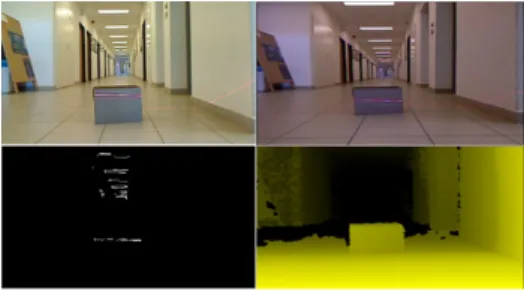
The comparison of the sensors are done indoor and outdoor conditions too. When we use the structured lighting sensor indoor environments the most significant disturbing element is the sudden light intensity changing at the border of lamps and other lighting objects because it can lead to false positive detection. (Fig 5).
Fig. 5. Sensitivity to ambient light. First two images in the first line is the color image, and second line is the sensed area. The 1th row shows the structured lighting sensor, and the 2nd row shows the results of the Kinect sensor. This measure happened on a corridor.
The Kinect sensor is less sensitive to the high intensity luminous flux of lighting objects (Fig 5), furthermore the lighting objects are detected by false negative but generally it includes only the lamp without the lighting fixture (Fig 6).
Fig. 6. Sensitivity to ambient light of the Kinect sensor. The second image is the sensed area. It shows that the Kinect can not detect the light sources.
The non-local and non-adaptive laser detection can causes mistakes when a largely different incident illumination is upon the surface of the object and that appears on the picture.
So the developed method works properly at certain lighting conditions only. The other problem is the illuminance in an office environment approximately have 500 to 750 lux, and the sun illuminance can reach 50,000 to 100,000 lux. The illuminance of the projected laser stripe approximately 5,000 lux.
Therefore our sensor which is based on laser projection works fine when the environment contains only objects which have illuminance under 5,000 lux.
C. Processing time of the sensors
Between the two sensors data processing speed has a significant difference. The Kinect sensor makes thirty and the structured lighting sensor makes two virtual depth maps in a second. Case of the structured lighting sensor the whole detection process (read the camera image, image preprocessing, detection of laser, make the depth map) running on the main computer. Case of the Kinect sensor the previous process is implemented on the hardware. This preprocessing takes over some computing power from the main computer.
D. Measurement range of the sensors
These sensors have different size of sensing area. The sensing depends on the distance and height of the objects (Fig 7). The figure shows sometimes the sensor can not sense the small objects (Fig 7, 1th and 2nd lines and 1th row).
Fig. 7. Measurement range of the structured lighting sensor. First line is the color image, second line is the detected area and third line is the virtual depth map. The 1 th and 2 rd row shows the structured lighting sensor, and the last row shows the Kinect sensor results. This images shows about a 3m2 area, which has some objects.
This kind of error is not possible at the Kinect, because this sensor uses a dot net for the measure (Fig 7). These sensors get a problem when the objects hide each other. In this case the measure signal projected the nearest object and the farthest object is hidden and this area is unknown.
The Kinect sensor has60◦visual angle and it has from half meter to four meter measurement range. The sensing area of the sensor is about8,37m2. The structured lighting sensor has a smaller measurement range. It is from 30 centimeter to two meter. The sensor sensing area about 2,2m2. These values depend on the external light sources. In case of the higher lighting the sensing are will be smaller. The values shows the Kinect sense four times bigger than the structured lighting sensor sensing area when the lighting is optimal.
E. Properties of the Kinect and the structured lighting sensor and processing times
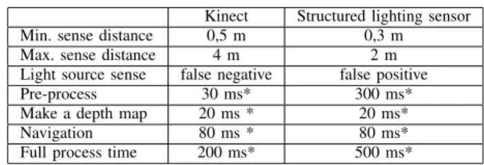
The Table I. summarize some of important properties of the structured lighting sensor and the Kinect sensor.
Kinect Structured lighting sensor
Min. sense distance 0,5 m 0,3 m
Max. sense distance 4 m 2 m
Light source sense false negative false positive
Pre-process 30 ms* 300 ms*
Make a depth map 20 ms * 20 ms*
Navigation 80 ms * 80 ms*
Full process time 200 ms* 500 ms*
TABLE I
SOME PROPERTIES OF THELASER AND THEKINECT SENSORS. THESE VALUES TESTED ON A*ASUS UL30V, INTELCORE2 DUO1,6 GHZ
COMPUTER.
VI. VISUALIZE THE UNKNOWN PATH
When the robot navigates in unknown environment the robot saves the path directions, distances and local maps during the progress. The navigation software represents the map as a matrix. Initially the map cells contain infinite values, the value of the wave front around the goal coordinate is one by straight an diagonal. The next step is that each surrounding pixels are calculated by the nearest actual wave front pixel value plus the distance of it. The algorithm will proceed until it reaches the start coordinate. At this point the target path is in the direction of the cell which has the lowest value. The algorithm does not have a memory but it computes the path very quickly, this will be a very important feature for real-time navigation [3]. We need to reduce the size of the virtual depth map to accelerate the pathfinder method. The depth map reduction is not possible with the basic image processing methods because possibly it can cause significant information loss. Therefore we developed a special virtual depth map accelerator method (Algorithm 2) which keeps all the objects and their position.
Algorithm 2 Reducate depth map fory= 0→hdo
forx= 0→w do if i(x, y) = 1then
j(scalex ,scaley ) = 1 or j(scalex ,scaley ) end if
end for end for
Where i is the source image, j is the reduced image, his the height of the image,wis the width of the image,scaleis the degree of the scale. Initially the reduced image matrix is filled with zero value. The specialty of the wave propagation method is, when an obstacle appears in front of the vehicle, the robot tries to avoid that immediately, therefore sometimes the robot navigates sinusoidal instead of straight (Fig 9). It is sometimes advantageous because the robot can avoid quickly
moving obstacles as soon as it possible. The explanation of the sinusoidal path shows on Figure 8. On the pictures we can see how the planned path changing in the reduction local maps during the navigation (the second picture show that when an obstacle appear in front of the robot, it starts to avoid that).
After the navigation can be visible the path [4], [5], [6]. The robot car has an incremental encoder. This sensor measures the drove distances. The sensor resolution about 0,36 impulsemm . Because inaccuracy of the mechanical structure (gear, wrist) the measuring distance with this encoder can maybe high.
This error is under two percent on linear path, starting from a standing start. We repeated the measurement twenty times, and the Table II. shows the results. The results show that the greater driven distance the measurement becomes more accurate.
Real distance Max. measure error Relative error
1 m 1,25 cm 1,3 %
2 m 2,7 cm 1,3 %
5 m 1,5 cm 0,3 %
TABLE II
INCREMENTAL ENCODER ACCURATE
The steering does not have feedback on the robot car. The control electronic has just receipt the received command and in this case the yaw angle is about 30◦. These angles error depend on:
• Deformation of the wheel
• Moving speed
• Battery power level
• Path surface
The false positive detection can cause faults during the navigation which based on structured light because the robot tries to avoid the false positive obstacles immediately. To eliminate this fault we declared a message puffer therefore the new direction is sent out only when the previous (which is stored in the puffer) and the actual direction (which is calculated from the local map) is equal. This method can discard faults which derived from the transient picture noises.
The disadvantage of this method is that the directions are calculated with half frequency. The Kinect sensor detects the faults false positive so this method is not necessary.
At the knowledge of the robot driven distances and the reorientation of it can be possible make a global map from
Fig. 8. The local map and the path changing during the navigation.
the local maps. At the beginning of navigation the software creates a global map (GM) for the path. Its resolution 10cm.
We assumed for the vehicle, the position and orientation on the map is always knownrx, ry, rd. At startup the robot position is in the middle of map rx = 0, ry = 0, rd = 0. After each section of a route (ithlocalmap)the software updated to the position of the vehicle, using the robot’s sensors data. Then the map building software inserts the local map (LM) to the global. The inserting algorithm uses the robot position and direction on the map (4). This step includes two transforms (rotation, translation).
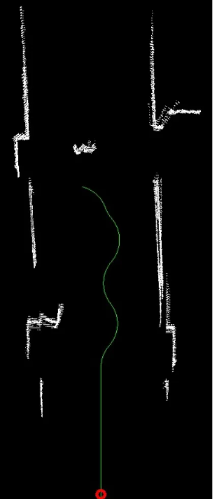
GM =insert(LMi, rxi, ryi, rdi) (4) The Figure 9 shows the vehicles path. Red colored line shows the drove path. Until this test the robot navigated across the corridor. It drove three meter, and it made thirty local maps. Accuracy of the map the size of the traversed path will be worse, because of the robot localization measurement type.
Fig. 9. The global map when was the robot drove across in a corridor. The red circle is the start position. Green line shows the measured path.
VII. CONCLUSION
Two types of sensors were tested in the paper. The Kinect sensor can sense bigger area, and the sensing is more accurate then the structured lighting sensor. But the Kinect sensor was not suitable for outdoor using.
The navigation software reduces the virtual depth map for the faster navigation. This algorithm is very fast, and valuable information not loses on the smaller map. We use the wave propagation algorithm for the robot navigation.
When the Kinect sensor used the robot is able to move maximum5 ms, because the image processing and navigation algorithm process time is about200 mson an ASUS UL30V, Intel Core 2 Duo 1,6 GHz computer. When the robot used the structured light sensor it is able to move maximum 2 ms at same parameters.
When the robot navigates in unknown environment the navigation software can make a global map for the navigation data (saved path directions, distances and local maps). This global map shows the path of the robot on the mapped environment.
REFERENCES
[1] György Csaba, László Somlyai, Zoltán Vámossy, Mobile Robot Navigation In Unknown Environment Using Structured Light 3rd IEEE International Symposium on Logistics and Industrial Informatics (LINDI), pp. 249-254, ISBN 978-1-4577-1842-7, 2011
[2] Microsoft Kinect SDK,
http://research.microsoft.com/en-us/um/redmond/projects/kinectsdk/
(Visited: 2011. jan. 21.)
[3] Steven M. LaValle, Motion Planning, Part II: Wild Frontiers IEEE Robotics and Automation Magazine, Vol. 18, No. 2, pp. 108-118, ISSN 1070-9932, 2011
[4] Gyula Mester,Intelligent Mobile Robot Motion Control in Unstructured Environments Acta Polytechnica Hungarica, Vol. 7, No. 4, pp. 153-165, ISSN 1785-8860, 2010
[5] Christopher M. Gifford, Russell Webb, James Bley, Daniel Leung, Mark Calnon, Joseph Makarewicz, Bryan Banz, Arvin Agah,A novel low-cost, limited-resource approach to autonomous multi-robot exploration and mapping Robotics and Autonomous Systems, Vol. 58, pp. 186-202, 2010
[6] Cory White, Daniel Hiranandani, Christopher S. Olstad, Keith Buhagiar, Timmy Gambin, Christopher M. Clark, The Malta Cistern Mapping Project: Underwater Robot Mapping and Localization within Ancient Tunnel Systems Journal of Field Robotics, Vol. 27, Issue 4, pp. 399-411, 2010