Map Building with RGB-D Camera for Mobil Robot
László Somlyai*, Zoltán Vámossy**
Óbuda University, Doctoral School of Applied Informatics, Hungary
*somlyai.laszlo@nik.uni-obuda.hu, **vamossy.zoltan@nik.uni-obuda.hu
Abstract—The paper deals with the issues of the autonomous navigation of mobile robots. Nowadays several automatic operated vehicles, robots are used widely from the industry (storage system) to the everyday use (automatic parking system).
The paper deals with the realization of a smaller sized robot vehicle which is capable for autonomous navigation. Within this framework we describe the realization of the vehicle, the developed board computer for navigation and the possible sensors as well.
At the beginning of the paper some developments are presented which also dealt with the autonomous navigation of robots and mapping their environment. In knowledge of these works we started to develop our robot system. In a former paper we presented our robot vehicle and an early navigation algorithm.
In the current paper it is summarized which sensors can detect the environment and the localization of the vehicle. The paper presents our experimental results about the accuracy of the Kinect sensor in more details.
I. INTRODUCTION
Nowadays several automatic operated vehicles, robots are used widely. In this paper we shortly describe the development of some smaller robot vehicle with autonomous navigation ability. Sensors for detection of the environment and method of processing the sensor data are summarized with the aim in which directions can we develop further our system. Our robot vehicle [1] was remade from a radio remote control vehicle and used different sensors to detect its workspace.
In [2] we compared an own developed sensor using structured lighting with the Kinect sensor. The measurement results of both sensors were combined with the odometer data of the displacement sensors to determine the two-dimensional global map merging the locals.
Disadvantage of the former system was if the path of the robot was determined by only the displacement sensors, the measurement errors are accumulating continuously. Now we are completing this system with optical-based localization.
With the data of the RGB-D sensor is definable the displacement between two consecutive measurements. With this more accurate optical displacement we can improve the quality of the map building of our former system.
II. OTHER AUTONOMOUS ROBOT SYSTEM
This part shows some similar development where the goal was creating autonomous robots. The "Towards Urban 3D Reconstruction From Video" [3] project realized a three- dimensional data acquisition system. The system prepares the virtual space from urban environment where the points are
GEO registered, so the three-dimensional points are related to GPS coordinate system. The system uses inertial displacement sensors and consecutive displacement for three-dimensional Camera Tracking.
The "RGB-D Mapping - Using Depth Cameras for Dense 3D Modeling of Indoor Environments" [4] paper deals with three-dimensional mapping of indoor environment. For mapping RGB-D camera is used. Which name is Prime Sense.
This camera is very similar to the later released Kinect sensor.
The system produces a three-dimensional point cloud from the source of data. It marks those specific points which can be seen on the consecutive pictures. Searching of the feature points the SHIFT detector is used and join of the point clouds happens with an algorithm named RGBD-ICP. Finally it searches closed-loops on the global map (loop-course algorithm), if the robot gets back to an already known area it recognizes this situation. In this way it is possible to minimalize the measurement errors during navigation.
The "Visual Odometry and Mapping for Autonomous Flight Using an RGB-D Camera" [5] project uses the detection system presented in the previous paper. It describes a method which is able to navigate a flying robot with the data of an RGB-D camera. This system uses a FAST feature point detector. Estimating of the initial displacement inertial system (IMU) is used.
In the paper "Interactive 3D Modeling of Indoor Environments with a Consumer Depth Camera" [6] a method is described which is able for the three-dimensional rebuilding of the environment by the data of an RGB-D camera.
This low-cost camera gives color and pixel-level depth information about the environment of the plane. From this information the method provides the three-dimensional map of the environment. In this virtual environment movement of the camera and the plane can be followed up.
This method is similar to the described one in the "Visual Odometry and Mapping for Autonomous Flight Using an RGB-D Camera" [5]. One of the differences is the feature point detection. In this case for determination of feature points SHIFT feature point detector is used. This paper describes a new RANSAC algorithm also, which uses visual elements as well.
The "Designing and Implementing a Platform for Collecting Multi-Modal Data of Human-Robot Interaction" [7] paper details a method of collecting video and audio recordings of people interacting with a simple robot interlocutor. The
NTX based robot, ”Herme” used a HD web-cam with built in speaker, light sensor, microphone and distance measurement sensor.
In most cases such a detection system was used which is able to provide information to the automatic navigation of the robot in unknown environment. The most common sensors are the RGB-D sensor, GPS and inertial navigation systems.
III. ROBOTCAR
An own robot vehicle was made for testing the sensors and our algorithm. The sensors were equipped on the vehicle and the control software is running on the laptop which is attached to the vehicle. The base of the robot is an1/8scaled RC electronic remote control car. Both of the axes of the vehicle have electronic drive and its front and back wheels are steerable by servo motor. The vehicle is relatively small sized, it this way it is suitable for indoor navigation as well, but it is able to carry smaller sensors and laptops. In Fig. 1 the robot vehicle can been seen.
There can be find two main electronic units on the robot.
It is possible to join more control units to the system. Now a motor drive and a CAN communication electronics can be find in the system. Primary task of the CAN bridge card is to transmit the CAN messages to the control computer.
The module is connected to the control computer by virtual serial port. The motor drive module is responsible for the movement of the vehicle. It is important to deal with forward and backward movement of the vehicle and changing the direction. Two H-bridges are responsible for the motor driving.
The traveled distance (∆l) in a time (∆t) can be defined by an incremental sensor fitted to the wheels of the car. Accuracy of the measurement is influenced by the quality of the ground [8], therefore the system works with sufficient accuracy only on plain surface.
IV. SUMMARIES OF SENSOR TYPES
For robot navigation it is important to know the present location and the current environment of the robot. Localization
Fig. 1. Our mobile robot system with laser based sensor to the left [1], and with Kinect sensor to the right [2].
can happen by different types of sensors. One group of the sensors is consisted of different displacement sensors.
The most common subtype of it is the encoder, for example the wheel-mounted encoder of the robot. The wheel- mounted displacement sensors can give the traveled distance.
Depending on the quality of the ground there can be a great measurement error [8].
The inertial measurement unit (IMU) is one of the displacement sensors independent by the quality of the ground. The sensor measures the spatial displacement of the system by accelerometer, digital compass and gyroscope.
The displacement sensors are accurate in small distances but in bigger distance the measurement errors are accumulating continuously. In this way definition of the position is more uncertain. Nowadays the sizes of the sensors using for inertial navigation greatly reduced. In this way it is possible to use them by smaller mobile systems [9].
The GPS system can give the global positioning with relatively high accuracy if there are an appropriate line of sight the GPS satellites. In small distances it can be greatly inaccurate than the displacement sensors, but the big advantage is that in bigger distances measurement errors are not accumulated. The GPS-based measurement can be used only in outdoor environment.
Another type of sensors is the ultrasonic and the leaser distance measure. Their accuracy can be great but can give little information at the same time.
Distance measurement can happen by visual way, for example by stereo camera. These cameras are called RGB-D camera because they also determine distance information to the pixels of the colorful picture. The advantage of the visual system is that it gives information about the environment and the detected objects, so it becomes possible building three-dimensional maps. The accuracy of these is not as good as the inertial systems, and the external factors can influence their operation. Nowadays RGB-D cameras are more common, for example the recent Kinect sensor. The main advantage of it is the little cost and the relatively small size. It was used for robot localization in more development and for map building.
Because of these advantages it is used in our system as well.
V. ACCURACY OF THEKINECT SENSOR
Kinect is an RGB-D sensor which was developed by the Microsoft at the end of 2010 [10]. The goal was to avoid the usage of joystick, keyboard and mouse for controlling games. Resolution of the color camera is640x480, which has pixel-level distances. Detection range of the depth camera is between0.5and4meters (at Windows sdk). At this range the accuracy of the depth camera is changing between10−60mm.
The Kinect contrary to the stereo cameras projects active measuring signal for distance measurement. In this way the sensor does not need to use external light for working. The sensor cannot detect its own measuring signal at external light, therefore it can give reliable measurement results only at indoor use. The four meters detection range makes possible the sensor usage on a smaller sized robot.
In the rest of the paper the accuracy, the calibration and the data processing of the Kinect sensor is examined.
• [ud, vd]T, is pixel coordinates of depth camera and the depth value of pixel is the following:δ(ud, vd).
• [uc, vc]T, is pixel coordinates of color camera.
• pd = [xd, yd, zd]T, is a three dimensional point in coordinate system of the depth camera.
• pc = [xc, yc, zc]T, is a three dimensional point in coordinate system of the color camera.
• pw = [xw, yw, zw]T, is a three dimensional point in coordinate system of the world.
• Xd={pd1, pd2, ..., pdn}, is set of three dimension points in coordinate system of the depth camera, where0≤n≤ k,k is number of the depth image pixels.
• Xw = {pw1, pw2, ..., pwm}, is set of three dimension points in coordinate system of the world, where m is number of points.
• fc = [fcx, fcy], cc = [ccx, ccy], are focal length and principal points of color camera.
• fd = [fdx, fdy], cd = [cdx, cdy], are focal length and principal points of depth camera.
• τcd={Rcd,tcd}, are transformation between coordinate system of the color camera and coordinate system of the depth camera.
The Kinect SDK contains the manufacturer parameters of the cameras, but these parameters are not accurately determined for each sensor. Before using the sensor it is necessary to calibrate it. Herrera C. and his colleagues published a calibration procedure for the Kinect sensor which defines the inartistic parameters of the camera and the transformation among the coordination systems of the camera [11]. In the paper the accuracy of the distances of the depth camera is not mentioned, so determination of depth map accuracy of the sensor was necessary.
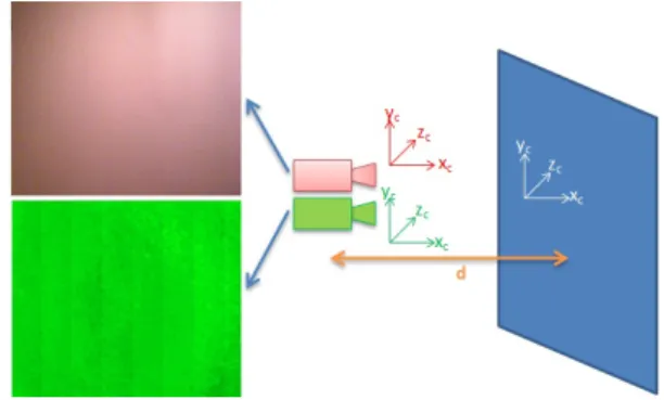
Determination of depth map accuracy was done in a test environment. The sensor was placed perpendicular to a flat surface, in different distances (d) and depth images where made about the flat surface. On the depth map the differences from real distances gives the measurement errors.
The measurement environment can be seen on Figure 2. On the left image of the Figure 3 can be seen a histogram of discrete measurement distances of the depth image. The Kinect sensor was placed one meter far from the wall.
A. The measurement error of the Kinect sensor
The accuracy of the sensor was characterized by two parameters. One of them is the biggest difference measured from the real difference, ∆d (1). It gives the biggest measurement error what the Kinect can give. Filtering out the smaller measurement noises was determined for all of the points on the depth picture and leaving the worst 1% point.
Results can be seen on the graph, Figure 4.
∆d=max(|d−min(δ(ud, vd))|,|d−max(δ(ud, vd))|) (1)
Fig. 2. Determination of accuracy of the depth camera. This image shows the color and depth images of the test environment. The blue rectangle is the perpendicular surface to the camera, in case ofddistance.
Fig. 3. Histogram of distance: on thexaxis are discrete distances of the depth image and the y axis shows numbers of measured points. The left image shows the original histogram of depth and the right image shows the histogram when the filter is used.
On the histograms of depth pictures it can be seen that distances approximate to the real values, but with enough large noise, which can give salient results. An averaging filter was used for reducing the measurement noise. Base of the algorithm is an averaging filter, but it omits those points where the distance measurement gave false result, so its value was zero (Algorithm 1).
Results after using the averaging filter can be seen on the Figure 4. The method is not able to filter out the biggest measurement errors, it can only reduce them.
Algorithm 1 Algorithm of filter fori= 1→(w−1) do
forj= 1→(h−1)do if δ(i, j)6= 0 then
Tk={δ(i−1, j−1), δ(i, j−1), δ(i+ 1, j−1), δ(i−1, j), δ(i, j), δ(i+ 1, j),
δ(i−1, j+ 1), δ(i, j+ 1), δ(i+ 1, j+ 1)}
δ0(i, j) = (P9
k=1Tk)/|T\ {0}|
end if end for end for
Where Tk is set of the actual and neighbors of the actual pixel values, and δ0(i, j)is the new depth value.
Fig. 4. Function of the distances and the biggest measurement error. The red line shows results for all pixels of dept image and the orange line shows the result without the worst1%measurement point. Green line shows the results for all pixels after used filter and blue line shows its without the worst1%
measurement point.
B. The standard deviation of Kinect sensor
The other argument is given by the standard deviation (s) of depth images. In the Figure 5 the deviation value as the function of the distance can be seen. Green color shows deviation for all of the points, red color shows the deviation after using the averaging filter. The averaging filter reduced the deviation of the sensor, but the biggest measurement errors were remained by the averaging filter.
VI. THREE DIMENSION MAP BUILDING
In this part of the paper the map is discussed, that how can it be possible to build up the three-dimensional map of the detected area of the robot, known the accuracy and intrinsic parameters of the sensor.
A. Earlier two dimensional map building
In an earlier paper [2] we dealt with two-dimensional map building by the data of Kinect sensor and structured light sensor. The system built a two-dimensional map using the
Fig. 5. The green line shows the standard deviations of the Kinect sensor for all pixels and the red line shows when the filter is used.
depth information. The matching information of the local maps was given by the incremental displacement sensors mounted on the mobile robot. The transmitters were able to give the two-dimensional displacement with relatively large accuracy between two consecutive sensor data. The Figure 6 shows the built global map made by one of the test.
B. Making a three-dimensional map
In the earlier paper only the depth data of a given horizontal line were used and the system was able to make only two- dimensional map. The next goal is to develop a system capable to build a three-dimensional map from the environment data combining the measurement information of the displacement sensors with the results of the Kinect sensor.
One condition to build a three-dimensional global map is to know the three-dimensional picture around the sensor in a moment. The Equation 2 gives the three-dimensional point (pd) from a pixel of the depth image. If this transformation is done on every pixels of the depth image, the result will be theXdset which is a three-dimensional point cloud about the actual environment of the sensor.
pd=
(ud−cdx)∗δ(ud, vd)/fdx
(vd−cdy)∗δ(ud, vd)/fdy
δ(ud, vd)
(2) During working of the system, measurements are done by the Kinect sensor, so the result is more consecutive point cloud (Xd1, Xd2, ...Xdn). The final goal that the system should be able to put the consecutive point clouds into one global space (Xw). For this it is necessary to know the range of displacement of the sensor. We can get the first estimation of the displacement from the displacement sensors, which were used in the earlier project.
If some of the visual information of the sensor is used, the determination of the transformation can be more accurate.
We can mark three-dimensional keypoints in the point cloud searching features in color image.
C. Point clouds matching
Fitting the point clouds made at different times, first of all the system searches the same points in the sets, using the keypoint descriptors. More feature detector algorithms are
Fig. 6. The figure shows a two dimensional global map from our previous paper [2]. White color sign the objects, green line sign the path of robot and the red circle shows the start position.
known, these are different in working accuracy and speed.
Some known feature point detector are SHIFT (Scale-invariant feature transform) [12], SURF (Speeded Up Robust Features) [13], KLT (Kanade-Lucas-Tomasi Feature Tracker) [14]. The Equation 3 is give a transformation between the point cloud points (pd) and the color image pixels ([u0c, v0c]T). Some pair of points remained for definition transformations between the sets.
[u0c, v0c]T =
fcx 0 0 0 fcy 0
∗p0d/z0d+cc (3)
,wherep0d=Rcd∗pd+tcd.
The RANSAC [15], RANdom SAmple Consensus algorithm is a general parameter estimation procedure, which can cope with the big salient of the input data as well. In the "Interactive 3D Modeling of Indoor Environments with a Consumer Depth Camera" [6] article a new type of RANSAC algorithm is described, which relies on visual elements as well.
The ICP [16] algorithm minimalizes the matching error of two accommodate point set. Usually it is used for matching two and three-dimensional point sets. The ICP algorithm needs an initial transformation, which is clarified by more steps. This first estimate can be the data given by the displacement sensors or the result of the RANSAC algorithm.
With matching method results of the measurements done earlier and later can also match to each other, if there is at least three corresponding point in the pictures. Know the transformations between each point clouds, it is possible to merge all point clouds.
VII. CONCLUSION
The paper presents our experimental results about the accuracy of the Kinect sensor in more details. The accuracy of the Kinect sensor was characterized by two parameters.
One of them is the biggest difference measured from the real difference and the standard deviation. These was represented as function of the distance. The deviation of the measurement was only 4−5mm for objects closer than one meter. For further objects it was even 20mm. However in that case the suggested modified averaging filter algorithm reduced the standard deviation to3mm.
Detection range of the Kinect sensor and its parameters, tested in our former paper, makes it suitable for using by smaller mobile robots in indoor usage. Now we are dealing with consecutive three-dimensional point clouds merging mentioned in the second part of the paper. With the data of the RGB-D sensor is definable the displacement between two consecutive measurements. With this more accurate optical displacement we can improve the quality of the map building of our former system. We are testing on global three-dimensional point cloud the different merging algorithms and their accuracy.
ACKNOWLEDGMENT
The author(s) gratefully acknowledge the grant provided by the project TÁMOP-4.2.2/B-10/1-2010-0020, Support of the scientific training, workshops, and establish talent management system at the Óbuda University.
REFERENCES
[1] Csaba Gy., Somlyai L., Vámossy Z., Mobile Robot Navigation In Unknown Environment Using Structured Light 3rd IEEE International Symposium on Logistics and Industrial Informatics (LINDI), pp. 249-254, ISBN 978-1-4577-1842-7, Budapest, Hungary, 2011
[2] Csaba Gy., Somlyai L., Vámossy Z., Differences Between Kinect and Structured Lighting Sensor in Robot Navigation In: Proc. SAMI 2012•10th IEEE Jubilee International Symposium on Applied Machine Intelligence and Informatics, pp. 85–90, ISBN: 978-1-4577-0195-5, IEEE Catalog Number CFP1208E-CDR, Herl’any, Slovakia, January 26-28, 2012
[3] Akbarzadeh, A., Frahm, J.-M., Mordohai, P., Clipp, B., Engels, C., Gallup, D., Merrell, P., Phelps, M., Sinha, S., Talton, B., Wang, L., Yang, Q., Stewenius, H., Yang, R., Welch, G., Towles, H., Nister, D., Pollefeys, M., Towards Urban 3D Reconstruction from Video 3D Data Processing, Visualization, and Transmission, Third International Symposium on, pp. 1-8, ISBN: 0-7695-2825-2, 2007
[4] P. Henry, M. Krainin, E. Herbst, X. Ren, and D. Fox.,RGB-D Mapping:
Using Depth Cameras for Dense 3D Modeling of Indoor Environments Proc. of the International Symposium on Experimental Robotics (ISER), 2010
[5] A. Huang , A. Bachrach , P. Henry , M. Krainin , D. Maturana , D. Fox , N. Roy,Visual Odometry and Mapping for Autonomous Flight Using an RGB-D Camera Int. Symposium on Robotics Research (ISRR), 2011 [6] Hao Du, Peter Henry, Xiaofeng Ren, Marvin Cheng, Dan B Goldman,
Steven M. Seitz, Dieter Fox, Interactive 3D Modeling of Indoor Environments with a Consumer Depth Camera Proceedings of the 13th international conference on Ubiquitous computing (UbiComp ’11), pp. 75-84, ISBN: 978-1-4503-0630-0, Beijing, China, 2011
[7] Brian Vaughan, Jing Guang Han, Emer Gilmartin, Nick Campbell, Designing and Implementing a Platform for Collecting Multi-Modal Data of Human-Robot Interaction Acta Polytechnica Hungarica, Vol. 9, No. 1, ISSN: 1785-8860, 2012
[8] Yussof H.,Robot Localization and Map Building ISBN 978-953-7619- 83-1, In-Teh, 2010
[9] Turóczi, A.,Pilóta nélküli légi járm˝uvek navigációs berendezései Bolyai Szemle, Vol. 1, pp. 179-193, 2006
[10] Microsoft Kinect SDK,
http://www.microsoft.com/en-us/kinectforwindows/ (Visited: 2012. jan.
26.)
[11] Herrera C., D., Kannala, J., Heikkilä, J., Accurate and Practical Calibration of a Depth and Color Camera Pair CAIP 2011, Part II, LNCS 6855, pp. 437-445, 2011
[12] David G. Lowe, Distinctive image features from scale-invariant keypoints International Journal of Computer Vision, pp. 9-110, 2004 [13] Herbert Bay, Andreas Ess, Speeded-UpRobustFeatures (SURF)
Computer Vision and Image Understanding, Vol. 110, Issue 3, pp. 346–359, 2008
[14] B. D. Lucas and T. Kanade,An iterative image registration technique with an application in stereo vision in Seventh International Joint Conference on Artificial Intelligence (IJCAI-81), pp. 674-679, 1981 [15] Konstantinos G. Derpanis,Overview of the RANSAC Algorithm Image
Rochester NY, Vol. 4, pp. 2-3, 2010
[16] S. Seeger, X. Laboureux, G. Hgausler,An Accelerated ICP-Algorithm Optical Sensing, Metrology and INspection, Annual Report, pp. 32, 2001
![Fig. 1. Our mobile robot system with laser based sensor to the left [1], and with Kinect sensor to the right [2].](https://thumb-eu.123doks.com/thumbv2/9dokorg/1149793.82558/2.892.60.440.840.1077/mobile-robot-laser-based-sensor-kinect-sensor-right.webp)