Comparing Calculated and Measured Losses in a
Satellite-Earth Quantum Channel
Comparing Calculated and Measured Losses in a Satellite-Earth Quantum Channel
Abstract—Long distance distribution of quantum states is necessary for quantum communication and large scale quantum experiments. Currently this distance is limited by channel loss.
Previous theoretical analysis [1] and proof of concept experiments [2] showed that satellite quantum communication may have lower losses than optical cable based counterparts.
Recently the QuESS experiment [3] realized the first satellite- Earth quantum channel. In this paper we compare theoretical predictions of different mathematical models with experimental results regarding channel loss. We examine the HV-5/7 model, HV-Night model and Greenwood model of optical turbulences, the geometric [4] and diffraction [5][6] models of beam wander and beam widening. Furthermore we take into account the effect of atmospheric gases and aerosols as well as the effect of pointing error. We find that theoretical predictions are largely in the same order of magnitude as experimental results. The exception is the diffraction model of beam spreading where our calculations yielded only one tenth of the measured value. Given the ever changing nature of weather conditions and the changing composition of atmospheric aerosols we conclude that calculated and measured losses are in good agreement.
Keywords—satellite; quantum communication; channel loss;
downlink;
I. INTRODUCTION
Quantum communication is the emerging field of sending and receiving messages using extremely weak signals. These signals could be single photons, coherent laser pulses or pairs of entangled photons. The signals are governed by quantum mechanics and thus behave fundamentally differently than classical counterparts.
One example of this unusual behavior is that unknown quantum bits cannot be observed or copied without running the risk of irreversibly changing them. These changes can later be detected revealing any eavesdropping attempt, which is extremely useful for cryptography. Another interesting property of quantum bits is that they can be entangled, meaning that their otherwise random behavior during measurement remains correlated even if they are separated by large distances.
These unusual behaviors allow for applications, which would not be possible otherwise. The most famous of these applications is quantum cryptography (cryptography with
mathematically proven security [7][8][9][10][11]). Since quantum channels cannot be wiretapped without alerting the communicating parties, it is possible to distribute cryptographic keys on a quantum channel and check if there was an eavesdropping attempt. If the keys were compromised they are discarded. Otherwise they can be used to encrypt secret massages.
Other possible uses of quantum channels include sending two bits of data at the cost of sending a single quantum bit in a full duplex quantum channel (a method called superdense or quantum dense coding [14][15]). Other large scale experiments have also been proposed that require entangled photon pairs (such as experiments testing theories about quantum gravity [12][13]).
A good and detailed theoretical introduction to quantum information can be found in [14] while a more practical and communication centric introduction can be found in [15].
However, quantum communication requires long distance distribution of quantum bits. The distance at which quantum bits can be transmitted is currently limited by channel loss─either the loss of an optical cable or losses in free space.
Experiments and theoretical works show that out of these two possibilities free space communication has lower losses. This motivated the race toward satellite-based quantum communication [16][17] which is currently unfolding even in the economic world of CubeSats [18][19].
The QuESS (Quantum Experiment at Space Scale) experiment realized the first satellite-Earth quantum channel.
The satellite produced entangled photon pairs and transmitted them to two ground stations at Lijiang and Delingha China via two downlinks. The transmitters onboard the satellite produced photons in the near infrared range. This means that the equipment and communication resembles optical downlinks and not radio frequency transmissions.
In this paper, we compare theoretical predictions for channel loss with measured values. This is necessary because theoretical predictions of quantum communication are based on mathematical models describing classical light beams. This approach requires the assumption that properties of the atmosphere are either completely or at the very least largely independent of light intensity and that individual photons behave in a way that is consistent with an infinitesimal part of a classical light beam.
Máté Galambos, László Bacsárdi
The research is connected to COST Action CA15220 Quantum Technologies in Space. The research was supported by the National Research
Development and Innovation Office of Hungary (Project No.
2017-1.2.1-NKP-2017-00001).
Máté Galambos is with Dennis Gabor College, Budapest, Hungary Lászlo Bacsárdi is with the Department of Networked Systems and Services, Budapest University of Technology and Economics, Budapest, Hungary
The research is connected to COST Action CA15220 Quantum Technologies in Space. The research was supported by the National Research Development and Innovation Office of Hungary (Project No. 2017-1.2.1-NKP- 2017-00001).
Máté Galambos is with Dennis Gabor College, Budapest, Hungary.
László Bacsárdi is with the Department of Networked Systems and Services, Budapest University of Technology and Economics, Budapest, Hungary
Comparing Calculated and Measured Losses in a Satellite-Earth Quantum Channel
Abstract—Long distance distribution of quantum states is necessary for quantum communication and large scale quantum experiments. Currently this distance is limited by channel loss.
Previous theoretical analysis [1] and proof of concept experiments [2] showed that satellite quantum communication may have lower losses than optical cable based counterparts.
Recently the QuESS experiment [3] realized the first satellite- Earth quantum channel. In this paper we compare theoretical predictions of different mathematical models with experimental results regarding channel loss. We examine the HV-5/7 model, HV-Night model and Greenwood model of optical turbulences, the geometric [4] and diffraction [5][6] models of beam wander and beam widening. Furthermore we take into account the effect of atmospheric gases and aerosols as well as the effect of pointing error. We find that theoretical predictions are largely in the same order of magnitude as experimental results. The exception is the diffraction model of beam spreading where our calculations yielded only one tenth of the measured value. Given the ever changing nature of weather conditions and the changing composition of atmospheric aerosols we conclude that calculated and measured losses are in good agreement.
Keywords—satellite; quantum communication; channel loss;
downlink;
I. INTRODUCTION
Quantum communication is the emerging field of sending and receiving messages using extremely weak signals. These signals could be single photons, coherent laser pulses or pairs of entangled photons. The signals are governed by quantum mechanics and thus behave fundamentally differently than classical counterparts.
One example of this unusual behavior is that unknown quantum bits cannot be observed or copied without running the risk of irreversibly changing them. These changes can later be detected revealing any eavesdropping attempt, which is extremely useful for cryptography. Another interesting property of quantum bits is that they can be entangled, meaning that their otherwise random behavior during measurement remains correlated even if they are separated by large distances.
These unusual behaviors allow for applications, which would not be possible otherwise. The most famous of these applications is quantum cryptography (cryptography with
mathematically proven security [7][8][9][10][11]). Since quantum channels cannot be wiretapped without alerting the communicating parties, it is possible to distribute cryptographic keys on a quantum channel and check if there was an eavesdropping attempt. If the keys were compromised they are discarded. Otherwise they can be used to encrypt secret massages.
Other possible uses of quantum channels include sending two bits of data at the cost of sending a single quantum bit in a full duplex quantum channel (a method called superdense or quantum dense coding [14][15]). Other large scale experiments have also been proposed that require entangled photon pairs (such as experiments testing theories about quantum gravity [12][13]).
A good and detailed theoretical introduction to quantum information can be found in [14] while a more practical and communication centric introduction can be found in [15].
However, quantum communication requires long distance distribution of quantum bits. The distance at which quantum bits can be transmitted is currently limited by channel loss─either the loss of an optical cable or losses in free space.
Experiments and theoretical works show that out of these two possibilities free space communication has lower losses. This motivated the race toward satellite-based quantum communication [16][17] which is currently unfolding even in the economic world of CubeSats [18][19].
The QuESS (Quantum Experiment at Space Scale) experiment realized the first satellite-Earth quantum channel.
The satellite produced entangled photon pairs and transmitted them to two ground stations at Lijiang and Delingha China via two downlinks. The transmitters onboard the satellite produced photons in the near infrared range. This means that the equipment and communication resembles optical downlinks and not radio frequency transmissions.
In this paper, we compare theoretical predictions for channel loss with measured values. This is necessary because theoretical predictions of quantum communication are based on mathematical models describing classical light beams. This approach requires the assumption that properties of the atmosphere are either completely or at the very least largely independent of light intensity and that individual photons behave in a way that is consistent with an infinitesimal part of a classical light beam.
Máté Galambos, László Bacsárdi
The research is connected to COST Action CA15220 Quantum Technologies in Space. The research was supported by the National Research
Development and Innovation Office of Hungary (Project No.
2017-1.2.1-NKP-2017-00001).
Máté Galambos is with Dennis Gabor College, Budapest, Hungary Lászlo Bacsárdi is with the Department of Networked Systems and Services, Budapest University of Technology and Economics, Budapest, Hungary
II. SOURCES OF LOSS IN SATELLITE-EATRH QUANTUM
CHANNELS
Free space losses can be induced by multiple causes. In the following section we detail the sources of loss that we have taken into account in our calculations.
A. Pointing Error
Errors in targeting may result in the photon missing the detector and thus contribute to the free space channel loss. In our calculations we used the reported [3] value of the targeting error measured in the QuESS experiment and assumed that the targeting error had a Gaussian profile as reported [3].
In the QuESS experiment the detector mirror of the telescope was a Cassegrain reflector [3]. We approximated this in our calculation by assuming that the cross section of the detector is a perfect circle with radius equal to the radius of the primary mirror and disregarded the blind spot created by the secondary mirror.
B. Beam Spreading and Beam Wander
Since the refraction of air is temperature dependent, fluctuations of air temperature can deflect and distort light signals. This effect depends on atmospheric conditions: the optical turbulence strength (denoted by Cn2) is a parameter that describes the strength of these fluctuations. Higher Cn2 values are associated with more beam widening and distortion. The magnitude of Cn2depends on wind speed, altitude and several other factors such as geographical features.
Atmospheric effects can also cause the center of a classical beam to wander. Higher Cn2 values are also associated with more beam wander. It is worth noting that we do not distinguish between beam wander and beam spreading here, since in the long term time average the beam wander can be described as just another source of beam spreading. The beam widening is characterized by the radial beam divergence angle (or beam divergence for short) which is measured in micro- radians.
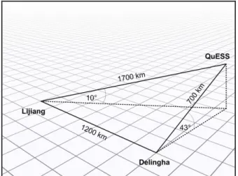
Fig. 1. Longest two-link distance between the satellite and the two ground stations.
C. Atmospheric Attenuation
Atmospheric gases and aerosols (solid particles of dust and liquid droplets) absorb and scatter light thus contributing to the channel loss. In our calculations, we took a semi-empirical approach. Instead of relying on purely theoretical calculations of molecular extinction we used experimentally measured values [20] of atmospheric transmittance.
This method is not only simple and easy to use, but it also gives us a more realistic picture of the aerosol profile as function of altitude than theoretical models. Since aerosol extinction is typically stronger than molecular extinction [20], we can expect a realistic result even with relatively inaccurate data about molecular extinction.
However, in these experiments [20] the wavelength was slightly different than in the QuESS experiment. Since aerosol extinction is mostly independent of wavelength (this statement is supported by both experimental data [20] and the theory of Mie-scattering [21]), we approximated aerosol extinctions by linear interpolation of measured values. In case of molecular extinction, we used the closest available analog which was a measurement performed using GaAs laser.
D. Efficienny of the Detector and the Optical Setup
Losses of the optical setup (due to imperfect detector efficiency, noise and inefficiencies in the photon generation process) are reported in the article [3] detailing the QuESS experiment. We have taken these efficiencies into account in our calculations.
III. CHANNEL LENGTHS AND ELEVATION ANGLES IN THE
QUESS EXPERIMENT
An important factor in determining the channel loss is the relative position of the ground station and the satellite. The elevation angle as seen from the ground station determines the effective thickness of the atmosphere whereas the distance to the satellite determines the channel length. Therefore both of these parameters are required to estimate the channel loss.
The article describing the results of the QuESS experiment [3] focuses on two geometric arrangements. One is the moment when the communication is established and losses are the highest, and the other is when the overall two-channel length is the shortest and the channel loss is the lowest. In both cases the authors disclose either the channel length or the elevation angle but not both. However one can be calculated from the other.
We used the satellite - ground station - Earth center triangle to calculate the missing parameters. According to our calculations when communication was established (see Figure 1.) the satellite-Lijiang distance was 1700 km and the elevation angle at Lijiang station was 10°. At the same time the satellite-Delingha channel length was 700 km and the elevation angle at Delingha was 43°.
The combined two channel length was the shortest when the satellite was 800-800 km from both Lijiang and Delingha stations (see Figure 2.) and could be seen at 36° elevation angle from both ground stations.
DOI: 10.36244/ICJ.2018.3.3
SEPTEMBER 2018 • VOLUME X • NUMBER 3 14
INFOCOMMUNICATIONS JOURNAL
Comparing Calculated and Measured Losses in a Satellite-Earth Quantum Channel
Máté Galambos and László Bacsárdi
Comparing Calculated and Measured Losses in a Satellite-Earth Quantum Channel II. SOURCES OF LOSS IN SATELLITE-EATRH QUANTUM
CHANNELS
Free space losses can be induced by multiple causes. In the following section we detail the sources of loss that we have taken into account in our calculations.
A. Pointing Error
Errors in targeting may result in the photon missing the detector and thus contribute to the free space channel loss. In our calculations we used the reported [3] value of the targeting error measured in the QuESS experiment and assumed that the targeting error had a Gaussian profile as reported [3].
In the QuESS experiment the detector mirror of the telescope was a Cassegrain reflector [3]. We approximated this in our calculation by assuming that the cross section of the detector is a perfect circle with radius equal to the radius of the primary mirror and disregarded the blind spot created by the secondary mirror.
B. Beam Spreading and Beam Wander
Since the refraction of air is temperature dependent, fluctuations of air temperature can deflect and distort light signals. This effect depends on atmospheric conditions: the optical turbulence strength (denoted by Cn2) is a parameter that describes the strength of these fluctuations. Higher Cn2 values are associated with more beam widening and distortion. The magnitude of Cn2depends on wind speed, altitude and several other factors such as geographical features.
Atmospheric effects can also cause the center of a classical beam to wander. Higher Cn2 values are also associated with more beam wander. It is worth noting that we do not distinguish between beam wander and beam spreading here, since in the long term time average the beam wander can be described as just another source of beam spreading. The beam widening is characterized by the radial beam divergence angle (or beam divergence for short) which is measured in micro- radians.
Fig. 1. Longest two-link distance between the satellite and the two ground stations.
C. Atmospheric Attenuation
Atmospheric gases and aerosols (solid particles of dust and liquid droplets) absorb and scatter light thus contributing to the channel loss. In our calculations, we took a semi-empirical approach. Instead of relying on purely theoretical calculations of molecular extinction we used experimentally measured values [20] of atmospheric transmittance.
This method is not only simple and easy to use, but it also gives us a more realistic picture of the aerosol profile as function of altitude than theoretical models. Since aerosol extinction is typically stronger than molecular extinction [20], we can expect a realistic result even with relatively inaccurate data about molecular extinction.
However, in these experiments [20] the wavelength was slightly different than in the QuESS experiment. Since aerosol extinction is mostly independent of wavelength (this statement is supported by both experimental data [20] and the theory of Mie-scattering [21]), we approximated aerosol extinctions by linear interpolation of measured values. In case of molecular extinction, we used the closest available analog which was a measurement performed using GaAs laser.
D. Efficienny of the Detector and the Optical Setup
Losses of the optical setup (due to imperfect detector efficiency, noise and inefficiencies in the photon generation process) are reported in the article [3] detailing the QuESS experiment. We have taken these efficiencies into account in our calculations.
III. CHANNEL LENGTHS AND ELEVATION ANGLES IN THE
QUESS EXPERIMENT
An important factor in determining the channel loss is the relative position of the ground station and the satellite. The elevation angle as seen from the ground station determines the effective thickness of the atmosphere whereas the distance to the satellite determines the channel length. Therefore both of these parameters are required to estimate the channel loss.
The article describing the results of the QuESS experiment [3] focuses on two geometric arrangements. One is the moment when the communication is established and losses are the highest, and the other is when the overall two-channel length is the shortest and the channel loss is the lowest. In both cases the authors disclose either the channel length or the elevation angle but not both. However one can be calculated from the other.
We used the satellite - ground station - Earth center triangle to calculate the missing parameters. According to our calculations when communication was established (see Figure 1.) the satellite-Lijiang distance was 1700 km and the elevation angle at Lijiang station was 10°. At the same time the satellite-Delingha channel length was 700 km and the elevation angle at Delingha was 43°.
The combined two channel length was the shortest when the satellite was 800-800 km from both Lijiang and Delingha stations (see Figure 2.) and could be seen at 36° elevation angle from both ground stations.
II. SOURCES OF LOSS IN SATELLITE-EATRH QUANTUM
CHANNELS
Free space losses can be induced by multiple causes. In the following section we detail the sources of loss that we have taken into account in our calculations.
A. Pointing Error
Errors in targeting may result in the photon missing the detector and thus contribute to the free space channel loss. In our calculations we used the reported [3] value of the targeting error measured in the QuESS experiment and assumed that the targeting error had a Gaussian profile as reported [3].
In the QuESS experiment the detector mirror of the telescope was a Cassegrain reflector [3]. We approximated this in our calculation by assuming that the cross section of the detector is a perfect circle with radius equal to the radius of the primary mirror and disregarded the blind spot created by the secondary mirror.
B. Beam Spreading and Beam Wander
Since the refraction of air is temperature dependent, fluctuations of air temperature can deflect and distort light signals. This effect depends on atmospheric conditions: the optical turbulence strength (denoted by Cn2) is a parameter that describes the strength of these fluctuations. Higher Cn2 values are associated with more beam widening and distortion. The magnitude of Cn2depends on wind speed, altitude and several other factors such as geographical features.
Atmospheric effects can also cause the center of a classical beam to wander. Higher Cn2 values are also associated with more beam wander. It is worth noting that we do not distinguish between beam wander and beam spreading here, since in the long term time average the beam wander can be described as just another source of beam spreading. The beam widening is characterized by the radial beam divergence angle (or beam divergence for short) which is measured in micro- radians.
Fig. 1. Longest two-link distance between the satellite and the two ground stations.
C. Atmospheric Attenuation
Atmospheric gases and aerosols (solid particles of dust and liquid droplets) absorb and scatter light thus contributing to the channel loss. In our calculations, we took a semi-empirical approach. Instead of relying on purely theoretical calculations of molecular extinction we used experimentally measured values [20] of atmospheric transmittance.
This method is not only simple and easy to use, but it also gives us a more realistic picture of the aerosol profile as function of altitude than theoretical models. Since aerosol extinction is typically stronger than molecular extinction [20], we can expect a realistic result even with relatively inaccurate data about molecular extinction.
However, in these experiments [20] the wavelength was slightly different than in the QuESS experiment. Since aerosol extinction is mostly independent of wavelength (this statement is supported by both experimental data [20] and the theory of Mie-scattering [21]), we approximated aerosol extinctions by linear interpolation of measured values. In case of molecular extinction, we used the closest available analog which was a measurement performed using GaAs laser.
D. Efficienny of the Detector and the Optical Setup
Losses of the optical setup (due to imperfect detector efficiency, noise and inefficiencies in the photon generation process) are reported in the article [3] detailing the QuESS experiment. We have taken these efficiencies into account in our calculations.
III. CHANNEL LENGTHS AND ELEVATION ANGLES IN THE
QUESS EXPERIMENT
An important factor in determining the channel loss is the relative position of the ground station and the satellite. The elevation angle as seen from the ground station determines the effective thickness of the atmosphere whereas the distance to the satellite determines the channel length. Therefore both of these parameters are required to estimate the channel loss.
The article describing the results of the QuESS experiment [3] focuses on two geometric arrangements. One is the moment when the communication is established and losses are the highest, and the other is when the overall two-channel length is the shortest and the channel loss is the lowest. In both cases the authors disclose either the channel length or the elevation angle but not both. However one can be calculated from the other.
We used the satellite - ground station - Earth center triangle to calculate the missing parameters. According to our calculations when communication was established (see Figure 1.) the satellite-Lijiang distance was 1700 km and the elevation angle at Lijiang station was 10°. At the same time the satellite-Delingha channel length was 700 km and the elevation angle at Delingha was 43°.
The combined two channel length was the shortest when the satellite was 800-800 km from both Lijiang and Delingha stations (see Figure 2.) and could be seen at 36° elevation angle from both ground stations.
INFOCOMMUNICATIONS JOURNAL
SEPTEMBER 2018 • VOLUME X • NUMBER 3 15
Fig. 2. Shortest two-link distance between the satellite and the ground sations.
It is worth mentioning that Figures 1. and 2. are merely illustrations and the triangles depicted on them are not proportional.
IV. OPTICAL TURBLULENCE
In order to model beam spreading and beam wander in the atmosphere we must know the atmospheric turbulence strength parameter (Cn2). There are several different turbulence profile models to choose from – these are typically curves fitted onto measured data. Since free space quantum communication is carried out during the night (when the background noise is the lowest) we focused on models applicable to nighttime conditions. In our calculations we used three specific models. These are:
Hufnagel-Valey 5/7 (or HV 5/7) model [22],
HV-Night model [22],
Greenwood model [22].
1) HV 5/7 model: The HV 5/7 is the most widely used model. It is a special case of the more general Hufnagel Valey model. According to the model the optical turbulence strength parameter Cn2 is given by the following equation:
exp 100 exp 1500
10 7 . 2
exp 1000 27 10
00594 . 0
16
5 10 2 2
A h h h h Cn W
where h is the altitude (measured in km), Wis 21 [m/s] and Ais 1.7∙10-14.
2) HV-Night model: The HV-Night model is another modification of the Hufnagel Valey model. In this model Cn2
is given by the following equation:
exp 100 10 9 . 1500 1 exp 10 02 . 3
exp 1000 10
16 . 8
15 17
10 54 2
h h
h h Cn
3) Greenwood model: The Greenwood model was developed for astronomical imaging from mountaintops. It gives Cn2as
exp 4000 10
3 . 4 10 10 2 .
2 13 1,3 17
2 h h
Cn
V. GEOMETRIC BEAM SPREADING MODEL
In this section we compare the calculated beam spreading with the measured values. The far field beam divergence has been reported to be 10 rad [3].
To calculate the beam wander we used the geometric approximation [4]. This treats optical turbulence as converging or diverging lenses. The radial beam divergence angle can be calculated as [4]:
12
0
3 1 2
2 2 3 2
1
1 92
, 2
dh
F h L L
L h L h C D H n
where L is the total channel length, H is the altitude of the satellite, h is the altitude above ground level in the integration path and L2is the beam’s slant path length corresponding to a given altitude. F is the focal range and D is the initial beam waist.
A. HV 5/7 Model
Calculating with the HV 5/7 model, the radial beam divergence comes out to be between 0.019 rad and 0.02 rad depending on which transmitting telescope of the QuESS satellite was used.
The lower value of the calculated beam spreading corresponds to the larger telescope (0.3 m diameter) and the higher beam spreading angle corresponds to the smaller telescope (0.18 m diameter).
However, the dependence of beam spreading on channel length seems to be negligible (our calculations yielded approximately the same result for each downlink). The most likely explanation for this independence is that beam spreading is comparably small in vacuum. This means that the spot size at the detectors plane is mostly determined by the part of the optical path that is in the atmosphere.
This path length in the atmosphere is a function of the elevation angle. However a lower elevation angle corresponds to a longer link distance if the altitude of the satellite is fixed.
Fig. 2. Shortest two-link distance between the satellite and the ground sations.
It is worth mentioning that Figures 1. and 2. are merely illustrations and the triangles depicted on them are not proportional.
IV. OPTICAL TURBLULENCE
In order to model beam spreading and beam wander in the atmosphere we must know the atmospheric turbulence strength parameter (Cn2). There are several different turbulence profile models to choose from – these are typically curves fitted onto measured data. Since free space quantum communication is carried out during the night (when the background noise is the lowest) we focused on models applicable to nighttime conditions. In our calculations we used three specific models. These are:
Hufnagel-Valey 5/7 (or HV 5/7) model [22],
HV-Night model [22],
Greenwood model [22].
1) HV 5/7 model: The HV 5/7 is the most widely used model. It is a special case of the more general Hufnagel Valey model. According to the model the optical turbulence strength parameter Cn2 is given by the following equation:
exp 100 exp 1500
10 7 . 2
exp 1000 27 10
00594 . 0
16
5 10 2 2
A h h h h Cn W
where h is the altitude (measured in km), Wis 21 [m/s] and Ais 1.7∙10-14.
2) HV-Night model: The HV-Night model is another modification of the Hufnagel Valey model. In this model Cn2
is given by the following equation:
exp 100 10 9 . 1500 1 exp 10 02 . 3
exp 1000 10
16 . 8
15 17
10 54 2
h h
h h Cn
3) Greenwood model: The Greenwood model was developed for astronomical imaging from mountaintops. It gives Cn2as
exp 4000 10
3 . 4 10 10 2 .
2 13 1,3 17
2 h h
Cn
V. GEOMETRIC BEAM SPREADING MODEL
In this section we compare the calculated beam spreading with the measured values. The far field beam divergence has been reported to be 10 rad [3].
To calculate the beam wander we used the geometric approximation [4]. This treats optical turbulence as converging or diverging lenses. The radial beam divergence angle can be calculated as [4]:
12
0
3 1 2
2 2 3 2
1
1 92
, 2
dh
F h L L
L h L h C D
H
n
where L is the total channel length, H is the altitude of the satellite, h is the altitude above ground level in the integration path and L2is the beam’s slant path length corresponding to a given altitude. F is the focal range and D is the initial beam waist.
A. HV 5/7 Model
Calculating with the HV 5/7 model, the radial beam divergence comes out to be between 0.019 rad and 0.02 rad depending on which transmitting telescope of the QuESS satellite was used.
The lower value of the calculated beam spreading corresponds to the larger telescope (0.3 m diameter) and the higher beam spreading angle corresponds to the smaller telescope (0.18 m diameter).
However, the dependence of beam spreading on channel length seems to be negligible (our calculations yielded approximately the same result for each downlink). The most likely explanation for this independence is that beam spreading is comparably small in vacuum. This means that the spot size at the detectors plane is mostly determined by the part of the optical path that is in the atmosphere.
This path length in the atmosphere is a function of the elevation angle. However a lower elevation angle corresponds to a longer link distance if the altitude of the satellite is fixed.
Fig. 2. Shortest two-link distance between the satellite and the ground sations.
It is worth mentioning that Figures 1. and 2. are merely illustrations and the triangles depicted on them are not proportional.
IV. OPTICAL TURBLULENCE
In order to model beam spreading and beam wander in the atmosphere we must know the atmospheric turbulence strength parameter (Cn2). There are several different turbulence profile models to choose from – these are typically curves fitted onto measured data. Since free space quantum communication is carried out during the night (when the background noise is the lowest) we focused on models applicable to nighttime conditions. In our calculations we used three specific models. These are:
Hufnagel-Valey 5/7 (or HV 5/7) model [22],
HV-Night model [22],
Greenwood model [22].
1) HV 5/7 model: The HV 5/7 is the most widely used model. It is a special case of the more general Hufnagel Valey model. According to the model the optical turbulence strength parameter Cn2 is given by the following equation:
exp 100 exp 1500
10 7 . 2
exp 1000 27 10
00594 . 0
16
5 10 2 2
A h h h h Cn W
where h is the altitude (measured in km), Wis 21 [m/s] and Ais 1.7∙10-14.
2) HV-Night model: The HV-Night model is another modification of the Hufnagel Valey model. In this model Cn2
is given by the following equation:
exp 100 10 9 . 1500 1 exp 10 02 . 3
exp 1000 10
16 . 8
15 17
10 54 2
h h
h h Cn
3) Greenwood model: The Greenwood model was developed for astronomical imaging from mountaintops. It gives Cn2as
exp 4000 10
3 . 4 10 10 2 .
2 13 1,3 17
2 h h
Cn
V. GEOMETRIC BEAM SPREADING MODEL
In this section we compare the calculated beam spreading with the measured values. The far field beam divergence has been reported to be 10 rad [3].
To calculate the beam wander we used the geometric approximation [4]. This treats optical turbulence as converging or diverging lenses. The radial beam divergence angle can be calculated as [4]:
12
0
3 1 2
2 2 3 2
1
1 92
, 2
dh
F h L L
L h L h C D H n
where L is the total channel length, H is the altitude of the satellite, h is the altitude above ground level in the integration path and L2is the beam’s slant path length corresponding to a given altitude. F is the focal range and D is the initial beam waist.
A. HV 5/7 Model
Calculating with the HV 5/7 model, the radial beam divergence comes out to be between 0.019 rad and 0.02 rad depending on which transmitting telescope of the QuESS satellite was used.
The lower value of the calculated beam spreading corresponds to the larger telescope (0.3 m diameter) and the higher beam spreading angle corresponds to the smaller telescope (0.18 m diameter).
However, the dependence of beam spreading on channel length seems to be negligible (our calculations yielded approximately the same result for each downlink). The most likely explanation for this independence is that beam spreading is comparably small in vacuum. This means that the spot size at the detectors plane is mostly determined by the part of the optical path that is in the atmosphere.
This path length in the atmosphere is a function of the elevation angle. However a lower elevation angle corresponds to a longer link distance if the altitude of the satellite is fixed.
![Fig. 5. Calculated and reported losses in case of the longest two-link distance in clear and hazy weather [3]](https://thumb-eu.123doks.com/thumbv2/9dokorg/1395925.116464/5.871.421.803.142.556/fig-calculated-reported-losses-longest-distance-clear-weather.webp)
