and C. Janáky*
†Department of Physical Chemistry and Materials Science, Interdisciplinary Excellence Centre, University of Szeged, Rerrich Square 1, Szeged H-6720, Hungary
‡ThalesNano Inc., Záhony u. 7, Budapest 1031, Hungary
*S Supporting Information
ABSTRACT: Electrochemical reduction of CO2 is a value-added approach to both decrease the atmospheric emission of carbon dioxide and form valuable chemicals. We present a zero gap electrolyzer cell, which continuously converts gas phase CO2 to products without using any liquid catholyte. This is thefirst report of a multilayer CO2electrolyzer stack for scaling up the electrolysis process. CO formation with partial current densities above 250 mA cm−2were achieved routinely, which was further increased to 300 mA cm−2 (with ∼95% faradic efficiency) by pressurizing the CO2
inlet (up to 10 bar). Evenly distributing the CO2 gas among the layers, the electrolyzer operates identically to the sum of multiple single-layer electrolyzer cells. When passing the CO2gas through the layers consecutively, the CO2 conversion efficiency increased.
The electrolyzer simultaneously provides high partial current
density, low cell voltage (−3.0 V), high conversion efficiency (up to 40%), and high selectivity for CO production.
W
ith either considering carbon dioxide as a feedstock for transportation fuels and commodity chemicals or aiming to reduce its atmospheric emission, electrochemical reduction of CO2 (CO2RR) is one of the major scientific and engineering challenges.1,2Various catalysts have been investigated in literally thousands of scientific works, identifying active and selective candidates and revealing important structure−property relationships with regard to catalyst size, shape, morphology, etc. As important examples of CO2RR, selective carbon monoxide formation was demon- strated on Ag electrodes, while multitudes of different alcohols and hydrocarbons form on copper catalysts.3 The large differences in the activities and selectivities of different catalysts in CO2RR are better understood by now and are also supported by theoretical studies on the reaction mechanism.4The industrial implementation of this technology neces- sitates the transformation of CO2to products at a high rate (i.e., current density, |jproduct| > 200 mA cm−2),5,6 which is inherently hampered in aqueous solutions by the low solubility of CO2. Continuous-flow gas-fed electrolyzers might offer the only viable technological solution to overcome this limi- tation.7,8 Apart from the high reactant concentration on the
catalyst surface ensured by the continuous CO2flow, it is also crucial to provide a high surface area for the electrochemical reaction. Hence, porous, gas diffusion electrodes (GDEs) are used in these electrolyzers, in which the triple phase boundary among the reactant gas, the catalyst, and the solid ionomer is maximized.9−11
To drive CO2RR in an economically feasible way, electrolyzer cells must be developed, which operate (i) at high current density (conversion rate), (ii) at low cell voltage (i.e., high energy efficiency), (iii) with high faradic efficiency (selectivity), and (iv) with high conversion efficiency. Notably, even though these four parameterstogetherdescribe the overall performance of an electrolyzer cell, very seldom are all of these reported in the scientific literature.
Over the past decade, a remarkable advancement was achieved with continuous-flow electrolyzers,7,8,12,13 most importantly with electrolyzers applying a dual (electrolyte + CO2gas) feed on the cathode (e.g., in microfluidic cells) and electrolyte feed at the anode.14,15 Cation16 or anion17−20
Received: May 26, 2019 Accepted: June 27, 2019 Published: June 27, 2019 Downloaded by UNIV OF SZEGED at 03:13:43:839 on July 09, 2019 from https://pubs.acs.org/doi/10.1021/acsenergylett.9b01142.
exchange membranes, bipolar membranes,21−23 (PEM, AEM, and BPM, accordingly), and even an inorganic diaphragm24 were proved to be applicable separators between the cell compartments. The effects of several parameters were scrutinized: electrolyte composition (e.g., electrolyte type, concentration, pH, etc.),14,23,25−27 structure of the micro- porous layer,28 catalyst morphology,29 and immobilizing the catalysts on different high surface area supports.30−32Some of these studies were performed applying pressurized CO2inlets (although not in the zero-gap configuration),16,25,33 further improving the performance. As a result, industrially relevant current densities, above|jproduct|= 200 mA cm−2, have become a reality with both Cu34−38and Ag30,32,39catalysts. Achieving high CO2 conversion efficiency, however, is a substantial challenge in such electrolyzers because of (i) the typically large gas head space above the GDEs and (ii) the CO2losses due to its dissolution in the catholyte.
Considerably less attention has been devoted to zero gap membrane electrolyzers, in which CO2gas is directly fed to the cathode.40−46These cells offer a simple technological solution, in which (i) the cell resistance can be very low (which translates to high energy efficiency), (ii) the inlet can be pressurized relatively easily, (iii) no catholyte is used and, hence, no liquid catholyte circulation loop is required, and finally, (iv) the losses due to CO2dissolution in the catholyte are minimal. The knowledge gathered with fuel cells and PEM water electrolyzers might contribute to future scale-up of this technology, as these are mature electrochemical technologies with cells of similar structure. Constructing large size and
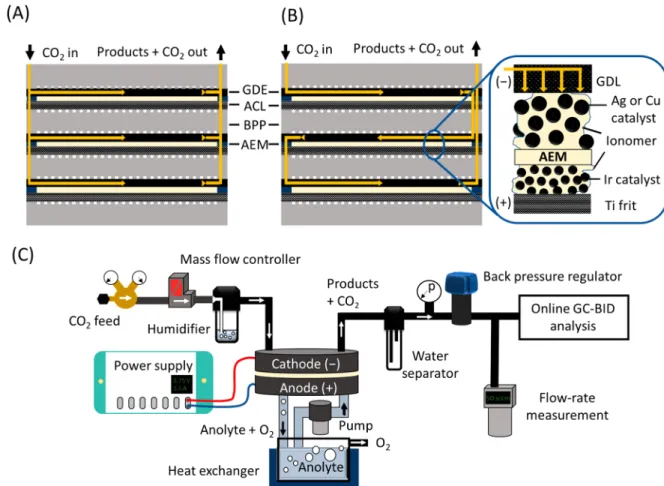
multilayer stacks is a common practice in both above- mentioned fields;47,48 nonetheless, it has not been demon- strated for CO2reduction yet. Implementation of this concept to CO2 electrolyzers can accelerate technology development, to scale up electrochemical CO2 reduction to an industrially relevant level. Here we present a zero gap CO2 electrolyzer stack, which consists of multiple electrolyzer layers and can operate with a pressurized CO2gas feed, without the need for any liquid catholyte. Furthermore, the flexibility of the presented design allows different connections between the layers of the electrolyzer regarding the distribution of the reactant CO2gas. Connecting the cells in parallel (Figure 1A), the gas is equally distributed among them; hence, pure CO2is fed to each cathode. On the other hand, when connecting the gas channels in series (Figure 1B), the total gasflux enters the first layer, and the off-gas (remnant CO2+ products) continues to the subsequent layer(s), hence allowing very high conversion efficiencies. From an electric perspective, the cells are connected in series in both cases (i.e., the same current flows through them). While the presented cell is completely scalable, the presented data were recorded with a cell which contained up to three electrolyzer units (having 61 cm2/cell active area), connected through bipolar plates. For testing the operation of the electrolyzer cell and to analyze the formed products, a test station was designed (Figure 1C) that was used throughout the experiments presented here. Further informa- tion regarding the cell (Figure S1) and the electrolyzer station is provided in theSupporting Information.
Figure 1. CO2 gas channel structure in an electrolyzer stack consisting of three layers in the (A) parallel and (B) serial connection configurations. BPP: bipolar plate; ACL: anode catalyst layer; GDE: gas diffusion electrode; GDL: gas diffusion layer; AEM: anion exchange membrane. (C) Schematicflowchart of the measurement setup.
Electrochemical CO2Reduction to Gas Phase Products Using Ag and Cu Catalysts. Ag nanoparticles and electrodeposited Cu nanocubes,49,50 immobilized on separate gas diffusion layers, were used to validate the operation of the electrolyzer in a single layer setup (see SEM images inFigures S2 and S3). The onset of a faradic process, read at 10 mA cm−2current density, was observed at −1.71 V with the Cu nanocube catalyst and
−2.01 V with the Ag nanoparticles on the linear sweep voltammetry curves (LSVs, Figure 2A). At voltages between
−1.2 and−1.5 V, a reduction peak, related to the reduction of copper oxide, was observed for the Cu nanocube catalyst in line with our previous study.51
Chronoamperometric curves were recorded for both catalysts at −2.75 V, where a stable operation was observed (Figure 2B). Gas chromatographic analysis of the composition of the product stream during electrolysis showed the formation of C2H4, CH4, CO, and H2for the Cu nanocube catalyst, while only CO and H2formed on the Ag catalyst (Figure S4A,B).
The cumulative faradic efficiency calculated for these products approached 100% in both cases, which suggests that the possible formation of other products is negligible. These results agree with earlier literature reports30,34and confirm that the CO2 gas enters the GDE and reaches the catalyst surface;
hence, the structure of the electrolyzer cell is appropriate for such studies. In the following, the detailed study on the effect of different experimental conditions and cell parameters is presented for the silver nanoparticle catalyst. Notably, in this
study we focus on the operation of the electrolyzer; hence, the cathode GDEs were formed from commercially available components (GDL, Ag catalyst, ionomer), based on earlier reports.17,19,20
Ef fect of the Operational Parameters. The effect of the cell voltage on the conversion rate and selectivity of CO2RR was investigated at constant CO2feed rate (Figure 3A). Increasing the cell voltage leads to an increase in the overall current density. The CO partial current density (jCO) peaks at−3 V, while the partial current density for H2production (jH2) grows monotonously with the cell voltage; hence, the hydrogen evolution reaction (HER) becomes dominant at higher cell voltages.
Regarding the CO2 gas feed rate, HER is dominant over CO2RR at lower values. The jH2 decreases and reaches a minimum value, whilejCO(together with the faradic efficiency of CO formation) increases and then peaks with the increasing CO2feed rate. Importantly, a partial current density for CO formation above −250 mA cm−2 was achieved (this is an average of multiple measurements on five different cell assemblies, where the champion cell resulted in −300 mA cm−2), while the faradic efficiency (FECO) was around 85%.
We emphasize that only hydrogen was formed as a byproduct;
no liquid or other gas phase products were detected. This simplifies the further processing of the product stream, as this syngas mixture can be directly used in the Fischer−Tropsch Figure 2. (A) LSV curves recorded atν= 10 mV s−1sweep rate and (B) chronoamperometric curves recorded atΔU=−2.75 V with different catalyst containing cathode GDEs. The cathode compartment was purged with humidified CO2at aflow rate ofu= 150 cm3min−1.
Figure 3. Partial current densities for CO and H2formation (A) at different cell voltages, at a CO2feed rate ofu= 500 cm3min−1, and (B) at ΔU=−3.00 V, as a function of the CO2feed rate to the cathode.
synthesis, after adjusting the proper CO to H2ratio using an external hydrogen source, such as a water electrolyzer cell.52
Electrolysis of CO2to CO in a Multilayer Electrolyzer Stack.
Assembling multilayer electrolyzer stacks, in which the cathode compartments are connected in parallel, is a way to increase the electrochemically active surface area without having to increase the lateral size of the electrolyzer. Comparing the results obtained with a single-cell electrolyzer and a stack cell consisting of three layers in parallel connection, the partial current density for CO formation and the CO2 conversion were very similar at all studied cell voltages (Figure 4A). This indicates that the CO2gas is evenly split among the layers in the stack and all individual cells operate with the same performance. We note again that the layers are connected in series electrically, and therefore the overall stack voltage can be controlled. Measuring the individual cell voltages during electrolysis, we found that the overall stack voltage is split evenly among them. Furthermore, the onset voltage (note that the stack voltage is normalized with the number of electrolyzer layers) and currents on the LSV curves recorded with a single- cell electrolyzer and a 3-layer electrolyzer stack in the parallel configuration are also comparable (Figure S4). The faradic efficiencies were also very similar: around 85% at lower cell voltages in both cases, which decreased to 75% at−3.0 V/layer
voltage. From a technological perspective, assembling multiple- layer electrolyzer stacks instead of parallelly operating multiple, single-cell electrolyzers decreases the capital investment costs, as the electrolyzer frame and the anolyte circulation loop only has to be built once and any further cell only requires an extra bipolar plate, insulation, and a membrane electrode assembly.
Connecting the cells in series is a completely different story.
In this case, the off-gas of thefirst electrolyzer layer is fed to the subsequent layers, where (part) of the remnant CO2 is transformed to products. Comparing the results measured with an electrolyzer stack consisting of three cells in serial configuration with that recorded for a single-layer cell, a large increase (ca. 70%) in CO2conversion was achieved even at low CO2 feed rates, where the CO2 conversion is already over 20% for the single-cell electrolyzer; hence, a CO2stream, diluted with CO and H2, reached the subsequent layers of the stack (Figure 4B). When increasing the gas feed rate, the difference increases drastically. At the highest studied gas feed rate, the CO2 conversion was three times higher in the electrolyzer stack, indicating the comparable operation of three individual cells. Furthermore, the faradic efficiency for CO production was above 95% in this case. We note that achieving high conversion decreases the separation and handling costs Figure 4. (A) CO partial current density and CO2conversion with a one-cell electrolyzer and an electrolyzer stack consisting of three cells, in the parallel configuration during electrolysis at different cell voltages with 433 cm3min−1CO2feed rate per cell at the cathode. (B) CO2
conversion with a single-cell electrolyzer and an electrolyzer stack consisting of three cells, in the serial configuration, at different CO2feed rates, atΔU=−2.75 V/cell.
Figure 5. Chronoamperometric curves recorded atΔU=−3.00 V withu= 750 cm3min−1CO2flow rate, humidified at (A)T= 85°C and (B)T= 60°C, while the cell was rinsed with ca. 50 cm3deionized water at the beginning of each hour. The CO faradic efficiency values were calculated from the analysis of the gas products by gas chromatography.
and, therefore, increases the value of the final gas mixture, strongly supporting the industrial implementation of CO2RR.
Stationary Operation of the CO2 Electrolyzer. When using anion exchange membranes and concentrated KOH solution in CO2RR, the precipitation of K2CO3 at the cathode side is a common issue, decreasing the performance of the electrolyzer by blocking the gas channels and the active catalyst sites.53 Different approaches can be envisioned to overcome this challenge. The first and most obvious one is to use pure deionized water as anolyte instead of strong alkaline solutions.
This tactic is feasible for some AEMs,54 and with the rapid development in this field, we envision that other membranes will also be available to be used with pure water (just like Nafion in water electrolyzer cells). For cells working with KOH, dissolving the precipitated K2CO3 during operation must be solved (without disassembling the cell), but as of yet, no ultimate engineering solution has been developed.
We present two possible avenues here. One is to increase the temperature of the humidified CO2 inlet and, thus, continuously feed more water vapor into the cell (Figure 5A). The other approach is to periodically flush the cell with liquid water (Figure 5B). In the first case, the temperature of the water humidifier was increased to 85°C, which led to the stable operation of the cell after a 30 min transient period at the beginning of the experiment. The FECO however, was considerably smaller (65−70%) throughout the measurement, compared to previous studies at lower inlet temperature (Figure 3). This trend can be attributed to the increased amount of water in the cell (i.e., higher probability of the HER). On the other hand, when the humidification was performed at lower temperature, a continuous current decay was observed during the measurements, due to K2CO3 precipitation. Therefore, the cell was flushed with deionized water at the beginning of each hour for 10 s. This rapid washing step healed the electrolyzer stack and restored the current to its original value (∼250−275 mA cm−2). The FECO was around 85% through the whole electrolysis. Comparing the current values at the end and at the beginning of each hour, no systematic decrease and, hence, no irreversible degradation were observed during the 8 h. Overall, both approaches avoid the accumulation of K2CO3precipitate. In the first case, the elevated temperature increases both the water amount in the CO2stream and the solubility of K2CO3. In the second case, K2CO3is washed out before larger plaque could build up.
Pressurized Electrolysis of CO2 to CO. Performing CO2RR with a pressurized CO2inlet is technologically important from multiple aspects. Some of the industrial CO2point sources are already under pressure, so the technology can be easily implemented. In addition, a pressurized product stream can be more easily transported, handled, and utilized.
Pressurizing the cathodic CO2feed leads to the positive shift of the onset potential on the LSV curves (Figure 6A), indicating a thermodynamically more favored CO2RR process.
The current also increases slightly with the applied pressure. In line with this, the CO formation partial current density during potentiostatic measurements initially increases from−250 mA cm−2above−285 mA cm−2with the applied pressure and then decreases at 10 bar (Figure 6B). The decrease at high pressure might be related to the enhanced crossover of CO2 (and possibly CO) through the employed anion exchange membrane; a notable decrease (above 20%) was observed in the gasflow rate during these measurements, even without any electrochemical polarization. More importantly, the selectivity for CO formation increases remarkably under pressure; a faradic efficiency of 95% (as compared to ∼85% at atmospheric pressure) was found for CO2RR even at 1 bar CO2 overpressure, which is not influenced by the further pressure increase. The operation of the electrolyzer was stable under intermediate pressure (4−6 bar) during the tests, for tens of hours.
The effect of pressure on the electrochemical properties of the electrolyzer cell is rather complex. The most important factors are the following: (i) the applied pressure presses the GDE on the membrane surface, hence ensuring better contact between them, (ii) the CO2 gas is forced to enter into the GDE structure, (iii) smaller relative amounts of water enter the cell with the humidified, pressurized CO2stream, and (iv) the concentration (activity) of the CO2increases. As one can see, some of these effects are simply mechanical while others are chemical, and it is not trivial to deconvolute them.
To further emphasize the complex effect of pressure, measurements similar to what is shown Figure 6 were performed with an electrolyzer built of the same components, but which was significantly underperforming compared to the average cells. Surprisingly, the effect of pressure was much larger in this case! A great current increase was seen in the currents on the LSV curves with increasing pressure (Figure 7A). The jCO showed a volcano type dependency, while the Figure 6. (A) LSV curves recorded atν= 10 mV s−1sweep rate and (B) partial current densities for CO and H2formation, and the ratio of these during electrolysis atΔU=−3.00 V, both as a function of the differential CO2pressure. The cathode compartment was purged with humidified CO2at aflow rate ofu= 750 ncm3min−1.
reaction selectivity increased continuously with the pressure (Figure 7B). Interestingly, the jCOand the FECOis very similar to what was shown for the well performing electrolyzer cells at intermediate pressure (p= 6 bar).
Two important conclusions can be drawn from these observations. First, when reporting the effect of pressure, it is very important to investigate and exclude all trivial effects (e.g., the compression of the GDE) and study cells which already have good performance at atmospheric pressure. Second, an electrolyzer cell underperforming at atmospheric pressure, in which the dimensions of the components are not perfectly matched, can function the same way under pressure as a properly assembled cell.
In summary, we developed a direct CO2gas-fed, zero gap electrolyzer cell, which can operate with different catalysts. By employing GDEs formed of commercially available compo- nents, CO formation partial current densities above−250 mA cm−2were routinely achieved. By pressurizing the CO2inlet, this could be increased close to−300 mA cm−2, and the CO to H2ratio was extraordinarily high in this case (above 20). The assembly and operation of a multilayer electrolyzer stack of any CO2 electrolyzer was demonstrated for the first time. We highlighted two possible scenarios for assembling multiple cells in an electrolyzer stack: one in which the electrolyzer layers are connected in parallel in terms of the gas feed, where hence the operation of electrolyzer stack is identical to the sum of multiple single-cell electrolyzers, and another one, where, when connecting the layers in series, the conversion rate increased significantly compared to a single-cell electrolyzer. These insights might trigger further development in scaling-up this fledging technology, which will bring us closer to its industrial implementation.
■
ASSOCIATED CONTENT*S Supporting Information
The Supporting Information is available free of charge on the ACS Publications website at DOI: 10.1021/acsenergy- lett.9b01142.
Experimental details and the following additional data:
schematic structure of the electrolyzer stack, SEM images of the electrodeposited Cu nanocube layers, SEM images of the spray-coated Ag nanoparticle layers, gas chromatographs recorded during potentiostatic
measurements with the Ag and Cu catalysts, and additional electrochemical measurements with the electrolyzer stack (PDF)
■
AUTHOR INFORMATION Corresponding Authors*E-mail:janaky@chem.u-szeged.hu(C. Janáky).
*E-mail:endrodib@chem.u-szeged.hu(B. Endrődi).
ORCID
B. Endrődi:0000-0003-3237-9222
C. Janáky:0000-0001-5965-5173 Notes
The authors declare the following competing financial interest(s): There is a patent application pending, filed by the authors of this paper and their institutions. Application number: PCT/HU2019/095001. Specifically, the patent application covers the details of the cell architecture, description of the individual components of the cell, and the electrolysis process.
■
ACKNOWLEDGMENTSThis project has received funding from the European Research Council (ERC) under the European Union’s Horizon 2020 research and innovation programme (Grant Agreement No.
716539). E.K. acknowledges the support of the New National Excellence Program of the Ministry of Human Capacities (Grant UNKP-18-3). This research was also supported by the
“Széchenyi 2020” program in the framework of the GINOP- 2.2.1-15-2017-00041 project.
■
(1) Chen, C.; Khosrowabadi Kotyk, J. F.; Sheehan, S. W. ProgressREFERENCES toward Commercial Application of Electrochemical Carbon Dioxide Reduction.Chem.2018,4(11), 2571−2586.(2) De Luna, P.; Hahn, C.; Higgins, D.; Jaffer, S. A.; Jaramillo, T. F.;
Sargent, E. H. What Would It Take for Renewably Powered Electrosynthesis to Displace Petrochemical Processes?Science 2019, 364(6438), No. eaav3506.
(3) Jones, J. P.; Prakash, G. K. S.; Olah, G. A. Electrochemical CO2 Reduction: Recent Advances and Current Trends.Isr. J. Chem.2014, 54(10), 1451−1466.
(4) Kortlever, R.; Shen, J.; Schouten, K. J. P.; Calle-Vallejo, F.;
Koper, M. T. M. Catalysts and Reaction Pathways for the Figure 7. (A) LSV curves recorded atν= 10 mV s−1sweep rate and (B) partial current densities for CO and H2formation and the ratio of these during electrolysis atΔU=−2.75 V, both as a function of the differential CO2pressure for a cell underperforming at atmospheric pressure. The cathode compartment was purged with humidified CO2at aflow rate ofu= 750 ncm3min−1.
Paradigm.ACS Energy Lett.2019,4(1), 317−324.
(10) Liu, K.; Smith, W. A.; Burdyny, T. Introductory Guide to Assembling and Operating Gas Diffusion Electrodes for Electro- chemical CO2Reduction.ACS Energy Lett.2019,4(3), 639−643.
(11) Burdyny, T.; Smith, W. A. CO2 Reduction on Gas-Diffusion Electrodes and Why Catalytic Performance Must Be Assessed at Commercially-Relevant Conditions. Energy Environ. Sci. 2019, 12, 1442−1453.
(12) Weekes, D. M.; Salvatore, D. A.; Reyes, A.; Huang, A.;
Berlinguette, C. P. Electrolytic CO2 Reduction in a Flow Cell. Acc.
Chem. Res.2018,51(4), 910−918.
(13) Jeanty, P.; Scherer, C.; Magori, E.; Wiesner-Fleischer, K.;
Hinrichsen, O.; Fleischer, M. Upscaling and Continuous Operation of Electrochemical CO2 to CO Conversion in Aqueous Solutions on Silver Gas Diffusion Electrodes.J. CO2 Util.2018,24, 454−462.
(14) Whipple, D. T.; Finke, E. C.; Kenis, P. J. A. Microfluidic Reactor for the Electrochemical Reduction of Carbon Dioxide: The Effect of pH.Electrochem. Solid-State Lett.2010,13(9), B109.
(15) Dufek, E. J.; Lister, T. E.; McIlwain, M. E. Bench-Scale Electrochemical System for Generation of CO and Syn-Gas.J. Appl.
Electrochem.2011,41(6), 623−631.
(16) Dufek, E. J.; Lister, T. E.; Stone, S. G.; McIlwain, M. E.
Operation of a Pressurized System for Continuous Reduction of CO2. J. Electrochem. Soc.2012,159(9), F514−F517.
(17) Kaczur, J. J.; Yang, H.; Liu, Z.; Sajjad, S. D.; Masel, R. I. Carbon Dioxide and Water Electrolysis Using New Alkaline Stable Anion Membranes.Front. Chem.2018,6, 263.
(18) Lee, J.; Lim, J.; Roh, C.-W.; Whang, H. S.; Lee, H.
Electrochemical CO2Reduction Using Alkaline Membrane Electrode Assembly on Various Metal Electrodes.J. CO2 Util.2019,31, 244− 250.
(19) Kutz, R. B.; Chen, Q.; Yang, H.; Sajjad, S. D.; Liu, Z.; Masel, I.
R. Sustainion Imidazolium-Functionalized Polymers for Carbon Dioxide Electrolysis.Energy Technology2017,5, 929−936.
(20) Yang, H.; Kaczur, J. J.; Sajjad, S. D.; Masel, R. I.
Electrochemical Conversion of CO2 to Formic Acid Utilizing SustainionTMMembranes.J. CO2 Util.2017,20, 208−217.
(21) Li, Y. C.; Zhou, D.; Yan, Z.; Goncalves, R. H.; Salvatore, D. A.;̧ Berlinguette, C. P.; Mallouk, T. E. Electrolysis of CO2 to Syngas in Bipolar Membrane-Based Electrochemical Cells. ACS Energy Lett.
2016,1(6), 1149−1153.
(22) Salvatore, D. A.; Weekes, D. M.; He, J.; Dettelbach, K. E.; Li, Y.
C.; Mallouk, T. E.; Berlinguette, C. P. Electrolysis of Gaseous CO2to CO in a Flow Cell with a Bipolar Membrane.ACS Energy Lett.2018, 3(1), 149−154.
(23) Dinh, C. T.; García De Arquer, F. P.; Sinton, D.; Sargent, E. H.
High Rate, Selective, and Stable Electroreduction of CO2to CO in Basic and Neutral Media.ACS Energy Lett.2018,3(11), 2835−2840.
(24) Haas, T.; Krause, R.; Weber, R.; Demler, M.; Schmid, G.
Technical Photosynthesis Involving CO2Electrolysis and Fermenta- tion.Nat. Catal.2018,1(1), 32−39.
(25) Gabardo, C. M.; Seifitokaldani, A.; Edwards, J. P.; Dinh, C.-T.;
Burdyny, T.; Kibria, M. G.; O’Brien, C. P.; Sargent, E. H.; Sinton, D.
T.; Atanassov, P.; Janáky, C. Morphological Attributes Govern Carbon Dioxide Reduction on N-Doped Carbon Electrodes. Joule 2019,DOI: 10.1016/j.joule.2019.05.007.
(30) Ma, S.; Luo, R.; Gold, J. I.; Yu, A. Z.; Kim, B.; Kenis, P. J. A.
Carbon Nanotube Containing Ag Catalyst Layers for Efficient and Selective Reduction of Carbon Dioxide. J. Mater. Chem. A 2016,4 (22), 8573−8578.
(31) Möller, T.; Ju, W.; Bagger, A.; Wang, X.; Luo, F.; Ngo Thanh, T.; Varela, A. S.; Rossmeisl, J.; Strasser, P. Efficient CO2 to CO Electrolysis on Solid Ni−N−C Catalysts at Industrial Current Densities.Energy Environ. Sci.2019,12(2), 640−647.
(32) Ma, S.; Lan, Y.; Perez, G. M. J.; Moniri, S.; Kenis, P. J. A. Silver Supported on Titania as an Active Catalyst for Electrochemical Carbon Dioxide Reduction.ChemSusChem2014,7(3), 866−874.
(33) Ramdin, M.; Morrison, A. R. T.; De Groen, M.; Van Haperen, R.; De Kler, R.; Van Den Broeke, L. J. P.; Trusler, J. P. M.; De Jong, W.; Vlugt, T. J. H. High Pressure Electrochemical Reduction of CO2
to Formic Acid/Formate: A Comparison between Bipolar Membranes and Cation Exchange Membranes.Ind. Eng. Chem. Res.2019,58(5), 1834−1847.
(34) Lan, Y.; Gai, C.; Kenis, P. J. A.; Lu, J. Electrochemical Reduction of Carbon Dioxide on Cu/CuO Core/Shell Catalysts.
ChemElectroChem2014,1(9), 1577−1582.
(35) Dinh, C.; Burdyny, T.; Kibria, M. G.; Seifitokaldani, A.;
Gabardo, C. M.; García de Arquer, F. P.; Kiani, A.; Edwards, J. P.; De Luna, P.; Bushuyev, O. S.; et al. CO2Electroreduction to Ethylene via Hydroxide-Mediated Copper Catalysis at an Abrupt Interface.Science 2018,360(6390), 783−787.
(36) Ma, S.; Sadakiyo, M.; Luo, R.; Heima, M.; Yamauchi, M.;
Kenis, P. J. A. One-Step Electrosynthesis of Ethylene and Ethanol from CO2 in an Alkaline Electrolyzer. J. Power Sources 2016,301, 219−228.
(37) Hoang, T. T. H.; Ma, S.; Gold, J. I.; Kenis, P. J. A.; Gewirth, A.
A. Nanoporous Copper Films by Additive-Controlled Electro- deposition: CO2 Reduction Catalysis. ACS Catal. 2017, 7 (5), 3313−3321.
(38) Mistry, H.; Varela, A. S.; Bonifacio, C. S.; Zegkinoglou, I.;
Sinev, I.; Choi, Y. W.; Kisslinger, K.; Stach, E. A.; Yang, J. C.; Strasser, P.; et al. Highly Selective Plasma-Activated Copper Catalysts for Carbon Dioxide Reduction to Ethylene. Nat. Commun. 2016, 7, 12123.
(39) Ma, S.; Liu, J.; Sasaki, K.; Lyth, S. M.; Kenis, P. J. A. Carbon Foam Decorated with Silver Nanoparticles for Electrochemical CO2 Conversion.Energy Technol.2017,5(6), 861−863.
(40) Delacourt, C.; Ridgway, P. L.; Kerr, J. B.; Newman, J. Design of an Electrochemical Cell Making Syngas (CO+H2) from CO2 and H2O Reduction at Room Temperature.J. Electrochem. Soc.2008,155 (1), B42−B49.
(41) Hori, Y.; Ito, H.; Okano, K.; Nagasu, K.; Sato, S. Silver-Coated Ion Exchange Membrane Electrode Applied to Electrochemical Reduction of Carbon Dioxide. Electrochim. Acta 2003, 48, 2651−
2657.
Polymer Electrolyte on Electrochemical Reduction of CO2.Sep. Purif.
Technol.2012,94, 131−137.
(47) Millet, P.; Ngameni, R.; Grigoriev, S. a.; Mbemba, N.; Brisset, F.; Ranjbari, A.; Etiévant, C. PEM Water Electrolyzers: From Electrocatalysis to Stack Development.Int. J. Hydrogen Energy2010, 35, 5043−5052.
(48) Marx, N.; Boulon, L.; Gustin, F.; Hissel, D.; Agbossou, K. A Review of Multi-Stack and Modular Fuel Cell Systems: Interests, Application Areas and on-Going Research Activities.Int. J. Hydrogen Energy2014,39(23), 12101−12111.
(49) Grosse, P.; Gao, D.; Scholten, F.; Sinev, I.; Mistry, H.; Roldan Cuenya, B. Dynamic Changes in the Structure, Chemical State and Catalytic Selectivity of Cu Nanocubes during CO2Electroreduction:
Size and Support Effects.Angew. Chem., Int. Ed.2018,57(21), 6192− 6197.
(50) Gao, H.; Wang, Y.; Xiao, F.; Ching, C. B.; Duan, H. Growth of Copper Nanocubes on Graphene Paper as Free-Standing Electrodes for Direct Hydrazine Fuel Cells. J. Phys. Chem. C 2012, 116 (14), 7719−7725.
(51) Janáky, C.; Hursán, D.; Endrődi, B.; Chanmanee, W.; Roy, D.;
Liu, D.; de Tacconi, N. R.; Dennis, B. H.; Rajeshwar, K. Electro- and Photoreduction of Carbon Dioxide: The Twain Shall Meet at Copper Oxide/Copper Interfaces.ACS Energy Lett.2016,1(2), 332−338.
(52) Van Der Laan, G. P.; Beenackers, A. A. C. M. Kinetics and Selectivity of the Fischer−Tropsch Synthesis: A Literature Review.
Catal. Rev.: Sci. Eng.1999,41(3−4), 255−318.
(53) Weng, L.-C.; Bell, A. T.; Weber, A. Z. Towards Membrane- Electrode Assembly Systems for CO2Reduction: A Modeling Study.
Energy Environ. Sci.2019,12(6), 1950−1968.
(54) Yin, Z.; Peng, H.; Wei, X.; Zhou, H.; Gong, J.; Huai, M.; Xiao, L.; Wang, G.; Lu, J.; Zhuang, L. An Alkaline Polymer Electrolyte CO2 Electrolyzer Operated with Pure Water. Energy Environ. Sci. 2019, DOI: 10.1039/C9EE01204D.