Anode Catalysts in CO 2 Electrolysis: Challenges and Untapped Opportunities
A ́ d á m Vass,
†Attila Korm á nyos,
†Zs ófia K ó sz ó , Bal á zs Endrődi, and Csaba Jan á ky*
Cite This:ACS Catal.2022, 12, 1037−1051 Read Online
ACCESS
Metrics & More Article RecommendationsABSTRACT:
The
field of electrochemical carbon dioxide reduction has developed rapidly during recent years. At the same time, the role of the anodic half-reaction has received considerably less attention.
In this Perspective, we scrutinize the reports on the best-performing CO
2electrolyzer cells from the past 5 years, to shed light on the role of the anodic oxygen evolution catalyst. We analyze how di
fferent cell architectures provide di
fferent local chemical environments at the anode surface, which in turn determines the pool of applicable anode catalysts. We uncover the factors that led to either a strikingly high current density operation or an exceptionally long lifetime. On the basis of our analysis, we provide a set of criteria that have to be ful
filled by an anode catalyst to achieve high performance. Finally, we provide an outlook on using alternative anode reactions (alcohol
oxidation is discussed as an example), resulting in high-value products and higher energy e
fficiency for the overall process.
KEYWORDS: CO2electrolysis, CCU, oxygen evolution reaction, electrocatalysis, pH effects
■
INTRODUCTIONElectrochemical conversion of carbon dioxide (CO2R) is an attractive way to simultaneously reduce atmospheric CO
2emissions and generate platform molecules that can be further processed to commodity/specialty chemicals.
1Although the
first studies on CO2R date back several decades,
2the
field has received broad and ever-growing attention only in the past 5
−10 years.
3,4The driving force behind this increased interest is at least twofold. One is the awareness of society about the implications of the rising atmospheric CO
2concentration. This facilitates the decision-makers to support the research and development of technologies that could decrease the CO
2emissions while generating high-value products. The other motivator is the increasing amount of intermittently available electricity (originating from solar and wind energy), which brought the renaissance of electrochemical technologies. These o
ffer a green and scalable alternative for energy storage and/or (in)organic synthesis.
A common feature in the most suitable electrolyzer cells of di
fferent structures is the continuously
flowing
fluid streams, removing the product(s) from the catalysts surface. A distinct attribute of such electrolyzer cells is that CO
2is fed in the gas phase to the cathode (and not as a CO
2-saturated solution, which is typical in batch cells), where the catalyst is immobilized on a porous gas di
ffusion layer (GDL), together forming a gas di
ffusion electrode (GDE).
5This approach ensures that the di
ffusion length of the reactant is reduced by several orders of
magnitude, leading to the intensi
fication of the conversion process.
6The development of GDEs and electrolyzer cells enabled conversion of CO
2to methane, ethylene, formate, or carbon monoxide at a high reaction rate, approaching or even exceeding
j= 1 A cm
−2(partial) current density.
7−12Industrially relevant reaction rates having already been achieved at acceptable energy e
fficiencies, more attention has been dedicated to the stability of such devices (i.e., operation for thousands of hours). Accordingly, processes hindering stability, such as electrode
flooding or precipitate formation in thecathode GDE, are gradually getting better understood.
13−15Until recently, very little scrutiny has been devoted to the anode reaction and the anode electrode itself. Notably, during any electrochemical process, the oxidation and the reduction (the anodic and cathodic reactions) proceed at the exact same rate, and therefore the slower reaction will determine the total reaction rate. While this rate limitation is typically associated with the cathodic CO2R in aqueous solutions and in electrolyzer cells operating at low current densities, this might not be true at higher current densities and during long-term operation. As
Received: October 29, 2021 Revised: December 11, 2021 Published: January 4, 2022
© 2022 The Authors. Published by
Downloaded via UNIV OF SZEGED on February 7, 2022 at 10:24:17 (UTC). See https://pubs.acs.org/sharingguidelines for options on how to legitimately share published articles.
more and more studies report on the operation of CO
2electrolyzer cells at high current density, it has become necessary to take a closer look at the anode side of these cells.
The anodic process paired to CO
2electrolysis is typically the electrochemical oxidation of water to form oxygen (i.e., the electrochemical oxygen evolution reaction, OER). In most of the papers published on CO2R in continuous-
flow electrolyzer cells, the anode catalyst is in contact with an (initially) alkaline electrolyte solution (anolyte; e.g., KOH). This provides conditions similar to the case of alkaline water electrolyzers.
Recent studies, however, revealed that in the case of recirculating the anolyte it is neutralized during continuous operation.
16−18Furthermore, in electrolyzer cells where the catalysts are directly pressed to a separator (i.e., fuel cell type or zero-gap cells; see
Figure 1), the surface chemistry might besigni
ficantly di
fferent from that in the electrolyte bulk, setting new requirements for the anode catalyst for stable operation. It is worth noting that these observations explain why Ir is a robust anode catalyst in CO
2electrolyzer cells, even though it is not stable in alkaline solutions.
18Performing OER as an anode process is preferred, as no mass transport issues are expected due to the presence of an ample amount of the reactant (>55 M reactant concentration) and the rapid removal of the O
2product. Moreover, water electrolysis is a well-studied and understood process, where a massive body of knowledge has been accumulated on the preferred anode catalysts, supports, binders, etc. On the other hand, a high
positive thermodynamic potential is required for water oxidation (1.23 V), which is further increased by the overpotential, rooted in the kinetic hindrance of the OER on any known catalyst.
Furthermore, the oxygen formed is of low value (
∼30
€/t).
19,20To tackle these issues, increasing attention has been given to performing alternative anode reactions in conjunction with CO2R.
19,21,22As a speci
fic example, oxidation of glycerol (e.g., to formate) occurs at several hundred millivolts lower potential in comparison to OER, which results in a lower electrolyzer cell voltage. This value-added approach increases the cost e
fficiency of the process, and therefore a rapid exploration of this
field is expected.
In this Perspective, we do not aim to provide a comprehensive
review on CO2R, as several thorough review articles are
available on this matter.
23−27Our goal was to clarify what
determines the chemical environment at the anode in
continuous-flow CO
2electrolyzer cells and how this affects
the overall performance. By analyzing and summarizing the
results published during the past few years, we concluded what
reaction conditions the anode catalyst must withstand during
long-term operation in di
fferent electrolyzer cells. We paid
special attention to those studies that reported exceptional
performance from any aspect. We have also brie
fly reviewed
studies on OER in near-neutral carbonate solutions, as these
best resemble the CO2R process conditions during long-term
operation. As an outlook, we highlight recent studies on
Figure 1.Schematics of the different cell structures employed in CO2electrolysis.coupling CO2R with alternative anode processes (especially alcohol oxidation).
■
ELECTROLYZER CELL TYPES AND SEPARATORS USED FOR CO2ELECTROLYSISTo identify potential anode catalysts for CO2R studies, it is essential to
first understand and clarify what conditions develop in CO
2electrolyzer cells, under which the given catalyst must be stable and active for OER. Di
fferent electrolyzer cell types have been utilized for CO
2electrolysis during the past few decades (Figure 1).
3,28These di
ffer in the number and properties of the applied
fluids (i.e., gas and liquid streams) and the number (and structure) of the cell components. As detailed in the following, these seemingly minor variances lead to completely altered operation, setting very di
fferent requirements for the cell constituents (e.g., cell body, membrane, etc.) and for the catalysts.
On the basis of the above factors, at least
five cell types can be identi
fied. In zero-gap electrolyzer cells (Figure 1, cell type I) the electrodes are pressed to a separator by the current collectors, with the catalyst layers facing toward each other. A liquid electrolyte solution is fed to the anode, while CO
2gas is constantly supplied to the cathode. Hybrid electrolyzer cells (Figure 1, cell type II) resemble most closely the structure of regular H-cells. The electrodes are in contact with thin liquid layers (anolyte and catholyte), which are divided by a separator.
The liquid electrolyte solutions are not static but are continuously
flown by the electrodes, and gas-phase CO
2is fed to the cathode. When the separator is pressed directly to one of the electrodes (i.e., removing the anolyte or catholyte), two further variants of these hybrid cells can be derived (Figure 1,
cell types III and IV). Finally, in micro
fluidic cells (Figure 1, cell type V) the electrodes are only separated by a continuously
flowing liquid electrolyte solution (i.e., there is no solid separator). The laminar
flow of the liquid is responsible for the removal of the formed products from the catalyst surfaces, hence avoiding the cross-talk of the electrode reactions.
Beyond the cell structure, the separator also a
ffects the reaction conditions, by governing the local chemical environ- ments at the cathode and anode sides. This e
ffect is more pronounced when the separator is in direct contact with the catalyst layer(s). If there is a liquid layer between the membrane and the catalyst layer(s), the e
ffect of the membrane is less direct, as the
flowing electrolyte solution(s) serve as bu
ffer layer(s), de
fining the local chemical environment (together with the electrode processes).
Inorganic diaphragms (e.g., ZrO
2) might serve as separa- tors,
29but ion exchange membranes are more frequently used due to their lower electrical resistance. Cation exchange membranes (CEMs), bipolar membranes (BPMs), and most frequently anion exchange membranes (AEMs) have been studied. As depicted in
Figure 2, the membrane dictates the iontransport processes between the electrodes, and consequently, it determines the chemical environment at the membrane
−catalyst interfaces (see also
Table 1). In the case of CEMs,cations, most importantly H
+ions, migrate from the anode to the cathode. Using AEMs, the ion transport occurs in the opposite direction: anions, most importantly OH
−, CO
32−, and HCO
3−, migrate through the membrane from the cathode to the anode.
BPMs consist of an AEM and a CEM, and therefore the ion conduction has two components.
30In the regular con
figuration (reverse BPM, r-BPM), the CEM is at the cathode side, while
Figure 2.Schematics of the ion transport processes through different membranes during CO2electrolysis in membrane-separated CO2electrolyzer cells. The reactions favored due to the local chemical environment of the electrode, defined by the membrane, are highlighted in bold.Table 1. Summary of Ion Transport Processes, the Conditions Emerging at the Membrane Surface, and the Main Obstacles during CO2Electrolysis Using Different Ion Exchange Membranes
surface pH surface species
anode cathode anode cathode transporting ions main obstacle(s)
CEM acidic acidic H+, anolyte H+, CO2, cations H+, cations from anolyte predominant cathodic HER AEM ∼neutral alkaline CO32− OH−, CO2, HCO3−,
CO32−
OH−, HCO3−, CO32−, (cations from anolyte) CO2crossover r-BPM alkaline acidic OH−,
anolyte
H+, CO2 H+and OH− Predominant cathodic HER
f-BPM acidic alkaline H+, anolyte OH−, CO2, HCO3−, CO32−
OH−, HCO3−, CO32−and H+, cations from anolyte
CO2formation between the membranes
the AEM is at the anode side. In this case, water dissociates at the junction of the membranes (often facilitated by a thin catalyst layer),
31while OH
−ions move toward the anode and H
+ions to the cathode. When the order of the membranes is switched (forward BPM, f-BPM), the transport of H
+ions from the anode and of OH
−, CO
32−, or HCO
3−ions from the cathode to the membrane junction maintain the ion conduction.
The membrane choice is vital for multiple reasons. The most trivial is that the ion conduction
which directly a
ffects the cell voltage
depends on the mobility of the charge carrier species and hence on the membrane type. The high mobility of H
+ions and the well-developed, thin yet robust CEMs together o
ffer the lowest cell resistance. Using CEMs, however, leads to an acidic surface pH at the cathode side of the membrane due to the H
+conduction. The high H
+ flux can be avoided by applying concentrated anolytes: cations from the anolyte (e.g., K
+) maintain the ion conduction between the electrodes.
7,8,32However, this results in a high local cation concentration at the cathode, where a carbonate precipitate might form, fading the performance of the electrolyzer cell.
13In cells where a catholyte
flows between the cathode and the membrane, thehigh H
+concentration at the cathode side of the membrane has only a minor in
fluence on the cathode surface pH, as that is mostly dictated by the liquid electrolyte. On the other hand, if the membrane is directly pressed to the cathode (Figure 1, cell types I and IV), the high surface concentration of H
+leads to a favored hydrogen evolution reaction (HER).
33For AEMs, the ion conduction is maintained mainly by CO
32−(and OH
−) ions under process conditions.
12,13,34This leads to an alkaline pH at the cathode side of the membrane (which is favorable for CO2R), while a high carbonate ion
flux reaches the anode side of the membrane. If a liquid layer
flows by the anode (cell types II and IV), this high carbonate concentration is diluted, and therefore it might not a
ffect the anode catalyst signi
ficantly.
When the anode is pressed to the membrane (cell types I and III), however, the carbonate ion
flux can detrimentally affect thestability of the anode catalyst. Another necessary consequence of the carbonate transport was revealed during long-term experi- ments with recirculated anolyte: the pH of the anolyte changes to near-neutral, even if a highly alkaline solution was applied at the beginning of the experiments.
17,18This sets new require- ments for the anode catalyst that must therefore be stable and active in OER at near-neutral pH and, in some cases, even in concentrated carbonate solution.
BPMs comprise a group of interesting, but less frequently studied, separators in CO2R studies. In regular operation (r-
BPM), acidic and alkaline environments develop at the cathode and anode sides, respectively. This again leads to increased HER selectivity at the cathode, if there is no bu
ffer layer included between the membrane and the catalyst layer (cell types I and IV). A further drawback of using r-BPMs is the increased cell voltage, rooted in the additional membrane
−membrane inter- face (and possible water dissociation catalyst) and in the voltage needed to facilitate water dissociation at the membrane
−membrane interface.
31In the case of f-BPMs, the cathode is alkaline, while the anode is acidic. In this con
figuration, the ion transport processes are both toward the junction of the membranes, where neutralization occurs. Depending on the charge carrier ions (CO
32−/HCO
3−/OH
−from the cathode, H
+or metal cations from the anode), water, metal carbonates, or CO
2forms at the membrane
−membrane junction. Water and metal carbonates can lead to electrode
flooding and resistance increase, respectively.
30In zero-gap cells (type I), the most probable scenario is carbonate conduction from the cathode and proton conduction from the anode (due to the high mobility of H
+in the typically used CEMs). In this case, CO
2is liberated from the reaction of H
+and CO
32−ions. This gas formation leads to the physical separation and eventual mechanical failure of the membranes.
35Note that this occurs in all types of cells, even if liquid electrolytes are in contact with the BPM, and it is therefore not trivial to operate an f-BPM-separated CO
2electrolyzer cell.
■
SELECTION CRITERIA FOR STUDIES TO BEINCLUDED IN OUR ANALYSIS ON OER CATALYSTS
In this Perspective, we limited our scope to the past 5 years. We note that, even in this relatively short period, an exponential increase in the publication rate was observed. To avoid losing focus, we de
fined a set of criteria that should be simultaneously ful
filled to be included in our analysis (Scheme 1). First, the reported current density should reach at least 100 mA cm
−2, and at least 50% of this must be consumed by the formation of CO2R products (this also means that the partial Faradaic e
fficiency of each product must be accurately reported). If these criteria were ful
filled for multiple measurements in a given paper, two entries were created: one containing the highest achieved current density (regardless of the duration of the experiment) and another with the current density applied/measured during the longest reported measurement. If more than one cell type was investigated in the same paper, the number of entries was multiplied by the cell types.
10,36−45Scheme 1. Visual Summary of How the Analyzed Entries Were Selected from the Literature for this Perspective
Unfortunately, numerous parameters (e.g., the length of the given experiment, pH over the course of the experiments, etc.) are poorly reported in a considerable number of studies. In some extreme cases, even such crucial parameters as the size of the electrolyzer cell, the anode catalyst employed, and/or the applied voltage/current density are missing. If the length of the given experiment was not provided, 10 min of measurement time was estimated (enough for a coupled gas chromatography measurement with a short program). Similarly, if the pH of the anolyte was not monitored throughout the experiments, it was estimated from the initial conditions (electrolyte composition).
Our analysis is based on a total of 121 articles in which the reported measurements met the above requirements, represent- ing a total of 209 entries. The number of entries used to create each
figure may di
ffer from the total quantity due to the unknown parameters detailed above.
■
OER CATALYSTS STUDIED IN CO2ELECTROLYZER CELLS SO FARIn almost half of the cases (47%), Ir was employed as the anode catalyst,
10,12,13,16,18,29,32,34,36−87Another 30% and 14% account for Ni
7−10,17,36,39,41−44,88−117and Pt,
32,114,118−133respectively, while only 9% is related to other metals, metal alloys, or carbon
11,45,60,117,134−140(Figure 3A). The dominance of Ir and Ni is rooted in the fact that these are the generally used catalysts in acidic and alkaline water electrolyzers, respectively. The frequent use of Pt is unexpected, considering that Pt is not among the most active OER catalysts in neither acidic nor
alkaline medium.
141We assume that choosing Pt might be reasoned by its acceptable stability during laboratory experi- ments and by the relevant experience of researchers with this catalyst. The alloys are all nickel alloys; however, we considered it important to distinguish between metallic Ni and its alloys.
CO2R studies are mostly performed in alkaline media (Figure
3B). The role of alkaline electrolytes at the anode is at leasttwofold. One is to ensure high conductivity and reduce cell resistance, resulting in an overall lower cell voltage. Additionally, part of the cations present in the anolyte can cross over to the cathode side under the operating conditions. As mentioned above, a high alkali cation concentration results in an excessive precipitate formation at the cathode side, which is detrimental for stable operation.
64,142On the other hand, in cells operating without liquid catholyte (cell types I and IV) the slow crossing of cations through the AEM during electrolysis could boost cell operation, and the presence of a small amount of cations at the cathode surface is necessary to achieve a high CO2R rate.
13,143Ni or Ni-based electrocatalysts are dominantly used under alkaline conditions due to their remarkable activity and stability.
Interestingly, Ir is the second most frequently applied electro-
catalyst, despite its known slow dissolution in highly alkaline
solutions.
18This might be because of the short duration of the
experiments or because of the gradual decrease of the anolyte
pH to a near-neutral value during continuous operation, as
detailed above. About one-third of the studies employed near-
neutral electrolytes at the anode. The trend concerning Ir and Ni
is reversed here, in favor of Ir. This is not surprising on the basis
Figure 3.(A) Pie chart showing how often a given anode catalyst is used in the articles referenced in this Perspective. The numbers reflect the number of entries created from the inspected literature references. Diagrams showing how frequently a given anode catalyst was studied (B) under acidic, alkaline, and neutral pH and (C) in different CO2electrolyzer cell types. The colors consistently indicate the different catalysts. Data points were gathered from refs7−13,16−18,29,32,34, and36−140.of the dissolution of Ni in neutral solutions, while Ir is stable (and active) during neutral pH OER.
18,144Finally, only a handful (
five) of the entries can be found under acidic conditions.
10,32,61It is clear from
Figure 3C that only three of theaforementioned
five cell types are frequently used: micro
fluidic cells operating without membrane separation (V), zero-gap cells
(I), and hybrid cells (II), the last two together accounting for about 90% of all studies. At
first sight, the dominance of hybridelectrolyzer cells is surprising, as their precise operation requires a complex test environment (two liquid pumps, mass
flow controller, pressure controllers, etc.). Their frequent use, however, is understandable, as their structure is the most similar to that of H-cells, typically employed in laboratory experiments
Figure 4.Diagrams showing (A) the geometric area distribution of the electrolyzer cells used (data points were gathered from refs7−13,16−18,29, 32,34,36−140,145, and146) and (B) the applied cell types as a function of the applied reaction temperature (data points were gathered from refs 7−13,16−18,29,32,34,36−140, and145−147).Figure 5.Current density as a function of the length of the experiment, marking (A) the different anode catalysts (data points were gathered from refs 7−13,16−18,29,32,34, and36−140), (B) the different electrolyzer cell structures, and (C) the formed main CO2R products (data points for (B) and (C) were gathered from refs7−13,16−18,29,32,34,36−140, and145−147). C2+ corresponds to any multicarbon product where the number of C atoms is equal to or higher than two.
(
“continuous-
flow H-cells
”). Additionally, these cells allow controlling the local pH at the anode and cathode separately, therefore providing optimal conditions for each process. Zero- gap CO
2electrolyzer cells build on the knowledge gathered on PEM and AEM water electrolysis, which also explains their prevalence. Their simple structure and operation o
ffer a relatively easy path for industrial implementation. Finally, micro
fluidic cells are simple and cost-e
ffective platforms for testing new catalysts in CO2R, which makes these ideal for rapid screening experiments.
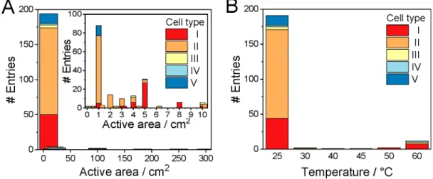
The vast majority (
∼85%) of the studies were performed in electrolyzer cells with a geometric surface area smaller than 5 cm
2(Figure 4A). Even more importantly, in almost half of the cases, the electrolyzer cell size used was 1 cm
2or smaller. While these studies report important and valuable
findings, it is worth mentioning that, in such a small size, the edge e
ffects might seriously distort the results. Furthermore, bubble management, heat management, and reactant transport might be notably di
fferent in larger electrolyzer cells; therefore, it is not trivial to transfer this knowledge to industrially relevant conditions (i.e., large electrolyzer cells and stacks).
The geometric surface area of the electrodes in the electrolyzers reached or approached 100 cm
2in the case of only
five entries, all of them operated with Ir catalyst in membrane-separated cells. This suggests that upscaling single electrolyte solution separated microfluidic electrolyzers (type V) might not be a viable option. The reason behind this could be the cross-talk of the electrode processes that becomes more intense in larger electrolyzer cells, where a longer residence time of the electrolyte solution assures more time for product transport to the other electrode.
Continuous-
flow CO2R measurements are typically per- formed at room temperature (Figure 4B). This is indeed surprising, especially since the sluggish kinetics of OER is typically boosted in water electrolyzers by increasing the reaction temperature. It is noteworthy that Ir-based PEM water electrolyzers operate in the 60
−80
°C temperature range, with an expected lifetime of 60000
−80000 h.
148For CO
2electrolyzer cells operating at room temperature, we note that the inner temperature of the cells is very seldom reported; the values
at least to our understanding
refer to the initial temperature of the anolyte/catholyte (i.e., ambient temper- ature). Inside the cell, however, the temperature increases due to the Joule heating e
ffect. The electrolyte solutions are typically pumped at a very low rate in cell types II and V, and therefore the inner temperature of these cells during operation could be significantly higher than the ambient temperature. Zero-gap cells (type I) are more often operated at elevated temperatures.
The anolyte recirculation rate is typically 10
−100 times higher than that in micro
fluidic/liquid
flow cells, allowing better temperature control.
Analyzing the highest reported CO2R current densities, values over
j= 1 A cm
−2were only reported in cell type II
7−11,32(with one exception performed in cell type I
12) and only in very short measurements. The reason behind this might be the high cation concentration at the cathode surface ensured by the concentrated catholyte solution (Figure 5A).
7,8,32The electro- lyte
flow also provides e
fficient product removal from the catalyst surface. At the beginning of these experiments, the existence of a real triple-phase boundary is envisioned (note the problem of short reaction times again!). During longer measurements, electrowetting and other structural changes might occur in the GDE, leading to higher water content and the
formation of a double phase boundary (solid/liquid) in the catalyst layer. These very high initial current densities are mostly transients and should therefore be handled with caution in aiming for industrial application. It is a typical trend to report transient high current densities and perform longer measure- ments at much lower current densities. In our opinion, this is acceptable until the di
fference between the highest presented current density and that used for stability demonstration is not too large (i.e., <50%). Showing a strikingly large current density but performing long measurements at 10
−20% of this value is, however, very misleading. Interestingly, Ni (or a Ni alloy) is the preferred choice of anode catalyst in the highest current density reports.
7−11Since a highly alkaline media at the anode is guaranteed by the anolyte in cell type II, which remains unchanged during short measurements, Ni is a stable anode catalyst.
The current density values decay rapidly with the length of the experiments (Figure 5), which suggests rapid cell failure at high reaction rates. This is typically attributed to unfavorable changes in the membrane or in the cathode GDE (e.g.,
flooding, precipitate formation, etc.). At the same time, changes in the anode catalyst morphology, composition, etc., are often overlooked and not studied. Less than 15% of the publications report on measurements longer than 100 h, and just a handful of reports can be spotted with measurements longer than 200 h.
With one exception,
41the longest measurements (>200 h) were performed using an Ir anode catalyst.
13,29,43,52,76,79,80,85This further proves that Ir is stable under process conditions (i.e., the anolyte pH decreases to a near-neutral value, hence avoiding the dissolution of Ir).
18For the exceptionally long measurement with Ni anode catalyst,
41it must be emphasized that (i) the measurement was performed in a hybrid electrolyzer cell, which allows control of the local chemical environment at the electrodes separately and (ii) the anolyte was periodically regenerated and hence its pH never decreased below pH 11.
This way, the alkaline environment was guaranteed at the anode during the whole measurement, ensuring that the Ni catalyst remained stable. Although this might be a viable approach (depending on the operational cost), it needs continuous monitoring and controlling of the anolyte composition and an extensive use of alkaline anolyte.
For the cell type, no apparent trend can be seen in the length of the experiments (Figure 5B). Measurements longer than 100 h are shown in cell types I
−III in an almost equal number of studies. This again signals that cell types I and II are preferred in CO2R studies, but the long-term studies in cell type III call attention to the applicability of these devices (taking into account, of course, the high cell voltage resulting from the cell construction).
76What limits the lifetime of these electrolyzer cells is not detailed in most cases. Post-mortem analysis of the cell elements
142(including all the MEA components and the cell hardware) is mostly lacking; therefore, it is di
fficult to identify the most important failure mechanisms. The latter is not very surprising, as the
field is in its infancy; only a small number of the publications report on longer experiments, where such fading mechanisms might appear.
The degradation of the anode catalyst is an important but
often neglected aspect of stability studies. As was mentioned
above, a possible anode fading mechanism is catalyst dissolution,
caused by the governing local chemical environment. The
importance of other degradation mechanisms, however, can be
envisioned similarly to water electrolyzer cells.
149Similarly to
the case of the cathode catalysts,
142these include the following.
•
Physical/chemical degradation of the catalyst layer, which includes the dissolution, detachment, and delamination of the catalyst particles and also the chemical/physical corrosion of the catalyst binder (e.g., PTFE or ion exchange ionomer).
•
Particle aggregation, which leads to the decrease of the electrochemically active surface area and to the blockage of the gas channels.
•
Catalyst poisoning (i.e., by cell component dissolution, by cathodically formed products, etc.), leading to decreased catalytic activity and hence an increased anode potential and cell voltage.
•
Degradation/passivation of the electrode support (i.e., oxide layer formation on a porous Ti electrode, or overoxidation of carbon-based electrodes), leading to increased cell resistance. Furthermore, because of the passivation of parts of the anode, higher local currents are driven through some parts of the catalyst layer. This high local current density (hot spot) can accelerate the catalyst (and membrane) degradation.
In terms of the reduction products, CO and HCOO
−were the main products during the longest experiments, both formed via the transfer of two electrons (Figure 5C). There is one outlier entry, reporting a stable CH
4production (i.e., eight-electron process) in a zero-gap cell for 700 h.
85The highest current densities were reported for systems where C2+ formation was the main CO2R pathway. High current densities, however, go hand in hand with short measurement times, highlighting that the partial crossover of the liquid products formed to the anode side can in
fluence the operation of the electrolyzer. This is inevitable for all currently used AEMs, where negatively charged products (e.g., acetate and formate) can transport through the membrane via electromigration, while neutral liquid products (such as alcohols) can cross via di
ffusion and electroosmotic drag.
150In extreme cases it can lead to the loss of 30
−40% of the formed products.
53As a next step, the migrated liquid products can be partially or fully oxidized at the anode. Several mitigation strategies are already in development, including tailoring the water uptake of the AEM (could help with the retention of neutral products), along with introducing product-blocking functional groups on the membrane surface and applying di
fferential pressure between the anode and cathode in a zero- gap cell con
figuration.
150,151As a
final remark on the reported results, we mention that the anode potential is provided in only a small fraction of the studies, as the focus is typically on the development of CO2R cathode catalysts. It is therefore not yet possible to compare the intrinsic activity of the di
fferent anode catalysts among the various studies.
■
ALTERNATIVE ANODE CATALYSTS FOR THE OERAs detailed above, for the long-term operation of CO
2electrolyzer cells either the anolyte must be continuously refreshed to maintain a highly alkaline pH or an anode catalyst should be used that is stable in OER at near-neutral pH. For the latter, Ir is stable; however, economic reasons urge the exploration of alternative OER catalysts. Water oxidation at near-neutral pH would also allow the use of cheap structural materials for constructing electrolyzer cells. The exploration of near-neutral pH water oxidation catalysts has therefore been long pursued.
152−156The knowledge and experience gathered in these related
fields might be used as a background in searching
for new anode catalysts for CO2R studies. Importantly, the catalytic activity of the catalyst candidates must be tested in relatively high concentration carbonate/bicarbonate bu
ffer solutions.
The majority of the studies on near-neutral pH OER were performed in phosphate and borate bu
ffer solutions. Only a few dozen papers were published on OER in carbonate bu
ffers.
These include studies with Co-, Fe-, Ir-, and Ni-based materials.
152−156A common point in these studies is the interaction between the catalyst and the carbonate/bicarbonate ions. This way, the active material on the catalyst surface is generated
in situduring the OER experiment. Recent studies demonstrated that carbonate ions could participate in the water oxidation reaction, leading to the formation of di
fferent radicals and also increasing the probability of peroxide formation.
157,158These considerations set important requirements for a potential anode catalyst in CO
2electrolyzer cells: namely, it must either remain unchanged during the reaction or the compound forming in its reaction with carbonate ions must be active for OER and it must be insoluble in the applied aqueous solution to avoid extensive catalyst loss.
■
VALUE-ADDED ANODE PROCESSES:ALTERNATIVES TO THE OER
From a purely thermodynamic perspective, it was found that more than 90% of the overall energy required to operate a CO
2electrolyzer cell is associated with the anodic OER.
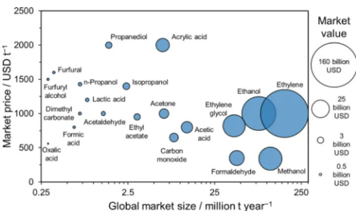
22This issue could be circumvented by coupling CO2R with alternative anode processes, occurring at less positive potentials. This would result in lower cell voltage along with the possible generation of high-value products at the anode. Such alternative processes could be the electrocatalytic oxidation of chloride ions, aliphatic and aromatic alcohols, amines, urea, hydrazine, and several biomass-derived compounds (e.g., 5- (hydroxymethyl)furfural (HMF), sorbitol, etc.).
159−164In addition, coupling value-added anode processes with CO2R maximizes the potential of utilizing waste carbon sources to generate valuable products. These circular processes will certainly play a key role in putting the chemical industry on a more sustainable path. Some products and their market potential are summarized in
Figure 6, on the basis of our ownliterature and market survey (note that even the smallest dots represent USD
∼0.5 billion market value).
A crucial criterion, which is often neglected in publications, is to ensure the overall (
“from CO
2source to the
final products
”) carbon-neutral/-negative operation of the CO
2electrolyzer (i.e.,
Figure 6.Market potential of chemicals possibly produced by coupling CO2R with organic oxidation reactions (our compilation).
we are not just using a sacri
ficial electron donor and generating CO
2). To realize this goal, several factors, such as the targeted products (e.g., the comparative scale of production of CO2R and small organic molecule oxidation products), the source/
purity of the substance to be oxidized (e.g., byproduct/waste stream), the overpotential, and the selectivity of the anode reaction have to be
simultaneouslyconsidered. In the existing literature, electrocatalytic alcohol oxidation (AOR) is the anode process most commonly paired with CO2R; therefore, the progress of this new research direction is demonstrated for that example.
■
ALCOHOL ELECTROOXIDATION TO HIGH-VALUE PRODUCTS PAIRED WITH CO2ELECTROLYSISWhile there are many examples that perform HER in parallel with electrocatalytic AOR, only a handful of reports can be found on its pairing with CO2R.
22,162,165−171Even more importantly, only three of these were performed in continu- ous-
flow cells.
22,165,166Type II cells were used in all studies with either strongly alkaline (2 M KOH) or near-neutral electrolytes (0.5 M KHCO
3). While driving AOR at the anode notably decreased cell voltages in all cases, the current densities achieved remained relatively low (below 100 mA cm
−2) and long-term stability was not demonstrated (the longest measurement was performed for 24 h, but current densities were below 10 mA cm
−2).
166Glycerol,
22,166glucose,
22,166methane,
22,166and 1,2- propanediol
165oxidations were also tested as anode processes.
Out of these, glycerol oxidation resulted in the lowest cell voltage (1.5 V
22and 1.55 V
166when Pt/C or Ni
0.9Au
0.1was used as the anode catalyst, respectively).
The rest of the cited studies were carried out in stagnant electrolytes, employing a membrane-separated H-cell con
fig- uration. The list of both the studied substances and electro- catalysts are more diverse here: in addition to glycerol,
167HMF,
167,170methanol,
168ethanol,
169isopropanol,
1711-phenyl- ethanol,
1714-methoxybenzyl alcohol,
171and benzyl alcohol
162were tested as potential oxidizable substance candidates (sometimes called fuels). Both heterogeneous (noble metals such as Pt and Pd, metal oxides such as CuO nanosheets and NiO nanoparticles, and a redox mediator (STEMPO)) and dissolved
162electrocatalysts were considered. Similarly to the measurements in
flow cells, substituting OER by AOR at the anode led to a decrease in the cell voltages. However, current densities fall behind those typically applied/measured in the standard CO2R/OER scenario (a maximum of 10
−15 mA cm
−2). As the AOR can follow several pathways (e.g., glycerol oxidation can proceed toward either glyceraldehyde or dihydroxyacetone)
163the selectivity has a key importance. In this vein, the e
ffect of the cell parameters (e.g., cell voltage, temperature, and current density) on product selectivity should be analyzed further.
Overall, all preceding research on paired CO2R/AOR has been based on model studies, employing commercially available electrocatalysts or redox mediators that were proven to be active toward AOR in strongly alkaline solutions. Therefore, there is a huge room for improvement in terms of the applied electro- catalyst
−substance pairs and the optimal operating conditions.
The main challenges to be solved in the foreseeable future can be summarized as follows:
Electrocatalyst.
The ideal electrocatalyst should show high activity and selectivity toward the desired AOR at neutral pH (due to the neutralization e
ffect discussed earlier). In addition, the given electrocatalyst should bear with excellent CO
32−tolerance. Moreover, intermediates/products formed during the AOR should not adsorb irreversibly on the catalyst surface, leading to a gradual decrease of the activity.
Oxidizable Substance (Fuel).
Little to no care was given in all the existing literature to the selection of the anode reaction by considering the overall carbon balance, except for one report.
22The only goal was to decrease the cell voltage in parallel with generating value-added products. In the long run, however, the anode reaction should be selected in a way that ensures the CO
2- neutral or -negative operation.
Operating Conditions.
To move toward industrial applications, promising electrocatalyst candidates should be tested in continuous-
flow cells. An optimum result should be found in terms of the electrolyte and substance concentrations.
Moreover, the e
ffect of temperature and elevated pressure on the selectivity of the AOR has to be scrutinized. The crossover of both the oxidizable substance and the products formed at the cathode side has to be considered, as they might cause the
flooding of the cathode GDE. This means that novel membranes have to be developed bearing an improved substrate/product retention.
■
SUMMARYWe have summarized recent reports on CO
2electrolyzer cells operating at high current density from the last 5 years, with the focus on the anodic half-reaction. We have analyzed these studies from the perspective of the applied anode catalyst, electrolyzer cell (
fluid inlets, structure, size), and operational parameters (pH, ion transport, temperature). We concluded that each cell type allows a di
fferent level of control during operation over the anode and cathode surface pH values, which are in some cases entirely determined by the applied cell type and the separator (and not the employed electrolyte). This fact limits the pool of applicable structural elements and catalysts.
We have shown that the neutralization of the recirculated anolyte implies that the anode catalysts must be stable under near-neutral OER conditions. This explained the fact that Ir was stable under such conditions, while Ni was applicable in cells where the alkaline conditions at the anode were continuously ensured. Possible Ir replacements are catalysts that possess high OER activity and stability under near-neutral conditions along while they tolerate a high CO
32−ion concentration. We have also uncovered that most studies reporting exceptionally high current density were carried out for very short timeframes, where no steady state can be expected either at the cathode or at the anode. Finally, we brie
fly outlined the opportunities and major challenges for coupling organic oxidation reactions to CO2R, showing that it is equally a catalyst and membrane challenge.
■
AUTHOR INFORMATION Corresponding AuthorCsaba Janáky−Department of Physical Chemistry and Materials Science, Interdisciplinary Excellence Centre, University of Szeged, Szeged H-6720, Hungary;
Email:
janaky@chem.u-szeged.huAuthors
Ádám Vass−Department of Physical Chemistry and Materials Science, Interdisciplinary Excellence Centre, University of Szeged, Szeged H-6720, Hungary
Attila Kormányos−Department of Physical Chemistry and Materials Science, Interdisciplinary Excellence Centre, University of Szeged, Szeged H-6720, Hungary Zsófia Kószó−Department of Physical Chemistry and
Materials Science, Interdisciplinary Excellence Centre, University of Szeged, Szeged H-6720, Hungary Balázs Endrődi−Department of Physical Chemistry and
Materials Science, Interdisciplinary Excellence Centre, University of Szeged, Szeged H-6720, Hungary
Complete contact information is available at:
https://pubs.acs.org/10.1021/acscatal.1c04978 Author Contributions
†
A.V. and A.K. contributed equally.
Funding
This project has received funding under the European Union’s Horizon 2020 research and innovation program from the European Research Council (ERC, Grant Agreement No.
716539) and the FlowPhotoChem project (Grant Agreement No. 862453). B.E. and A.K. also acknowledge
financial support by the János Bolyai Research Scholarship of the Hungarian Academy of Sciences. This work was further supported by the U
́NKP-21-5 New National Excellence Program of the Ministry for Innovation and Technology from the source of the National Research, Development and Innovation Fund (B.E.).
Notes
The authors declare no competing
financial interest.
■
(1) De Luna, P.; Hahn, C.; Higgins, D.; Jaffer, S. A.; Jaramillo, T. F.;REFERENCES Sargent, E. H. What Would It Take for Renewably Powered Electrosynthesis to Displace Petrochemical Processes?Science 2019, 364(6438), eaav3506.(2) Hori, Y.; Murata, A.; Takahashi, R. Formation of Hydrocarbons in the Electrochemical Reduction of Carbon Dioxide at a Copper Electrode in Aqueous Solution.J. Chem. Soc. Faraday Trans. 1 Phys.
Chem. Condens. Phases1989,85(8), 2309.
(3) Endrődi, B.; Bencsik, G.; Darvas, F.; Jones, R.; Rajeshwar, K.;
Janáky, C. Continuous-Flow Electroreduction of Carbon Dioxide.Prog.
Energy Combust. Sci.2017,62, 133−154.
(4) Weekes, D. M.; Salvatore, D. A.; Reyes, A.; Huang, A.;
Berlinguette, C. P. Electrolytic CO2 Reduction in a Flow Cell.Acc.
Chem. Res.2018,51(4), 910−918.
(5) Liu, K.; Smith, W. A.; Burdyny, T. Introductory Guide to Assembling and Operating Gas Diffusion Electrodes for Electro- chemical CO2Reduction.ACS Energy Lett.2019,4(3), 639−643.
(6) Burdyny, T.; Smith, W. A. CO2 Reduction on Gas-Diffusion Electrodes and Why Catalytic Performance Must Be Assessed at Commercially-Relevant Conditions.Energy Environ. Sci.2019,12(5), 1442−1453.
(7) García de Arquer, F. P.; Dinh, C. T.; Ozden, A.; Wicks, J.;
McCallum, C.; Kirmani, A. R.; Nam, D. H.; Gabardo, C.; Seifitokaldani, A.; Wang, X.; Li, Y. C.; Li, F.; Edwards, J.; Richter, L. J.; Thorpe, S. J.;
Sinton, D.; Sargent, E. H. CO2Electrolysis to Multicarbon Products at Activities Greater than 1 A cm−2.Science2020,367(6478), 661−666.
(8) Grigioni, I.; Sagar, L. K.; Li, Y. C.; Lee, G.; Yan, Y.; Bertens, K.;
Miao, R. K.; Wang, X.; Abed, J.; Won, D. H.; García de Arquer, F. P.; Ip, A. H.; Sinton, D.; Sargent, E. H. CO2Electroreduction to Formate at a Partial Current Density of 930 mA cm−2with InP Colloidal Quantum Dot Derived Catalysts.ACS Energy Lett.2021,6(1), 79−84.
(9) Yan, X.; Chen, C.; Wu, Y.; Liu, S.; Chen, Y.; Feng, R.; Zhang, J.;
Han, B. Efficient Electroreduction of CO2to C2+products on CeO2
modified CuO.Chem. Sci.2021,12(19), 6638−6645.
(10) Zheng, T.; Liu, C.; Guo, C.; Zhang, M.; Li, X.; Jiang, Q.; Xue, W.;
Li, H.; Li, A.; Pao, C. W.; Xiao, J.; Xia, C.; Zeng, J. Copper-Catalysed
Exclusive CO2 to Pure Formic Acid Conversion via Single-Atom Alloying.Nat. Nanotechnol.2021,16, 1386.
(11) Ma, W.; Xie, S.; Liu, T.; Fan, Q.; Ye, J.; Sun, F.; Jiang, Z.; Zhang, Q.; Cheng, J.; Wang, Y. Electrocatalytic Reduction of CO2to Ethylene and Ethanol through Hydrogen-Assisted C−C Coupling over Fluorine- Modified Copper.Nat. Catal.2020,3(6), 478−487.
(12) Endrődi, B.; Kecsenovity, E.; Samu, A.; Halmágyi, T.; Rojas- Carbonell, S.; Wang, L.; Yan, Y.; Janáky, C. High Carbonate Ion Conductance of a Robust PiperION Membrane Allows Industrial Current Density and Conversion in a Zero-Gap Carbon Dioxide Electrolyzer Cell.Energy Environ. Sci.2020,13(11), 4098−4105.
(13) Endrődi, B.; Samu, A.; Kecsenovity, E.; Halmágyi, T.; Sebők, D.;
Janáky, C. Operando Cathode Activation with Alkali Metal Cations for High Current Density Operation of Water-Fed Zero-Gap Carbon Dioxide Electrolysers.Nat. Energy2021,6(4), 439−448.
(14) Leonard, M. E.; Orella, M. J.; Aiello, N.; Román-Leshkov, Y.;
Forner-Cuenca, A.; Brushett, F. R. Flooded by Success: On the Role of Electrode Wettability in CO2 Electrolyzers That Generate Liquid Products.J. Electrochem. Soc.2020,167(12), 124521.
(15) De Mot, B.; Ramdin, M.; Hereijgers, J.; Vlugt, T. J. H.;
Breugelmans, T. Direct Water Injection in Catholyte-Free Zero-Gap Carbon Dioxide Electrolyzers.ChemElectroChem.2020,7(18), 3839− 3843.
(16) Ma, M.; Clark, E. L.; Therkildsen, K. T.; Dalsgaard, S.;
Chorkendorff, I.; Seger, B. Insights into the Carbon Balance for CO2 Electroreduction on Cu Using Gas Diffusion Electrode Reactor Designs.Energy Environ. Sci.2020,13(3), 977−985.
(17) Haspel, H.; Gascon, J. Is Hydroxide Just Hydroxide? Unidentical CO2Hydration Conditions during Hydrogen Evolution and Carbon Dioxide Reduction in Zero-Gap Gas Diffusion Electrode Reactors.ACS Appl. Energy Mater.2021,4(8), 8506−8516.
(18) Vass, Á.; Endrődi, B.; Samu, G. F.; Balog, Á.; Kormányos, A.;
Cherevko, S.; Janáky, C. Local Chemical Environment Governs Anode Processes in CO2Electrolyzers.ACS Energy Lett.2021,6, 3801−3808.
(19) Na, J.; Seo, B.; Kim, J.; Lee, C. W.; Lee, H.; Hwang, Y. J.; Min, B.
K.; Lee, D. K.; Oh, H.-S.; Lee, U. General Technoeconomic Analysis for Electrochemical Coproduction Coupling Carbon Dioxide Reduction with Organic Oxidation.Nat. Commun.2019,10(1), 5193.
(20) Shin, H.; Hansen, K. U.; Jiao, F. Techno-Economic Assessment of Low-Temperature Carbon Dioxide Electrolysis.Nat. Sustain.2021, 4, 911−919.
(21) Vass, Á.; Endrődi, B.; Janáky, C. Coupling Electrochemical Carbon Dioxide Conversion with Value-Added Anode Processes: An Emerging Paradigm.Curr. Opin. Electrochem.2021,25, 100621.
(22) Verma, S.; Lu, S.; Kenis, P. J. A. Co-Electrolysis of CO2and Glycerol as a Pathway to Carbon Chemicals with Improved Technoeconomics Due to Low Electricity Consumption.Nat. Energy 2019,4(6), 466−474.
(23) Jin, S.; Hao, Z.; Zhang, K.; Yan, Z.; Chen, J. Advances and Challenges for the Electrochemical Reduction of CO2to CO: From Fundamentals to Industrialization.Angew. Chemie - Int. Ed.2021,60 (38), 20627−20648.
(24) Nitopi, S.; Bertheussen, E.; Scott, S. B.; Liu, X.; Engstfeld, A. K.;
Horch, S.; Seger, B.; Stephens, I. E. L.; Chan, K.; Hahn, C.; Nørskov, J.
K.; Jaramillo, T. F.; Chorkendorff, I. Progress and Perspectives of Electrochemical CO2 Reduction on Copper in Aqueous Electrolyte.
Chem. Rev.2019,119(12), 7610−7672.
(25) Chen, C.; Khosrowabadi Kotyk, J. F.; Sheehan, S. W. Progress toward Commercial Application of Electrochemical Carbon Dioxide Reduction.Chem.2018,4(11), 2571−2586.
(26) Lu, Q.; Jiao, F. Electrochemical CO2Reduction: Electrocatalyst, Reaction Mechanism, and Process Engineering.Nano Energy2016,29, 439−456.
(27) Garg, S.; Li, M.; Weber, A. Z.; Ge, L.; Li, L.; Rudolph, V.; Wang, G.; Rufford, T. E. Advances and Challenges in Electrochemical CO2 Reduction Processes: An Engineering and Design Perspective Looking beyond New Catalyst Materials.J. Mater. Chem. A2020,8(4), 1511− 1544.
(28) Ma, D.; Jin, T.; Xie, K.; Huang, H. An Overview of Flow Cell Architectures Design and Optimization for Electrochemical CO2 Reduction.J. Mater. Chem. A2021,9, 20897−20918.
(29) Haas, T.; Krause, R.; Weber, R.; Demler, M.; Schmid, G.
Technical Photosynthesis Involving CO2 Electrolysis and Fermenta- tion.Nat. Catal.2018,1(1), 32−39.
(30) Blommaert, M. A.; Sharifian, R.; Shah, N. U.; Nesbitt, N. T.;
Smith, W. A.; Vermaas, D. A. Orientation of a Bipolar Membrane Determines the Dominant Ion and Carbonic Species Transport in Membrane Electrode Assemblies for CO2reduction.J. Mater. Chem. A 2021,9(18), 11179−11186.
(31) Oener, S. Z.; Foster, M. J.; Boettcher, S. W. Accelerating Water Dissociation in Bipolar Membranes and for Electrocatalysis. Science 2020,369(6507), 1099−1103.
(32) Huang, J. E.; Li, F.; Ozden, A.; Sedighian Rasouli, A.; García de Arquer, F. P.; Liu, S.; Zhang, S.; Luo, M.; Wang, X.; Lum, Y.; Xu, Y.;
Bertens, K.; Miao, R. K.; Dinh, C.-T.; Sinton, D.; Sargent, E. H. CO2 Electrolysis to Multicarbon Products in Strong Acid.Science2021,372 (6546), 1074−1078.
(33) Delacourt, C.; Ridgway, P. L.; Kerr, J. B.; Newman, J. Design of an Electrochemical Cell Making Syngas (CO + H2) from CO2and H2O Reduction at Room Temperature.J. Electrochem. Soc.2008,155(1), B42−B49.
(34) Xu, Y.; Edwards, J. P.; Liu, S.; Miao, R. K.; Huang, J. E.; Gabardo, C. M.; O’Brien, C. P.; Li, J.; Sargent, E. H.; Sinton, D. Self-Cleaning CO2Reduction Systems: Unsteady Electrochemical Forcing Enables Stability.ACS Energy Lett.2021,6(2), 809−815.
(35) Pătru, A.; Binninger, T.; Pribyl, B.; Schmidt, T. J. Design Principles of Bipolar Electrochemical Co-Electrolysis Cells for Efficient Reduction of Carbon Dioxide from Gas Phase at Low Temperature.J.
Electrochem. Soc.2019,166(2), F34−F43.
(36) She, X.; Zhang, T.; Li, Z.; Li, H.; Xu, H.; Wu, J. Tandem Electrodes for Carbon Dioxide Reduction into C2+ Products at Simultaneously High Production Efficiency and Rate.Cell Reports Phys.
Sci.2020,1(4), 100051.
(37) Gu, Z.; Shen, H.; Chen, Z.; Yang, Y.; Yang, C.; Ji, Y.; Wang, Y.;
Zhu, C.; Liu, J.; Li, J.; Sham, T. K.; Xu, X.; Zheng, G. Efficient Electrocatalytic CO2Reduction to C2+ Alcohols at Defect-Site-Rich Cu Surface.Joule2021,5(2), 429−440.
(38) Vennekoetter, J. B.; Sengpiel, R.; Wessling, M. Beyond the Catalyst: How Electrode and Reactor Design Determine the Product Spectrum during Electrochemical CO2Reduction.Chem. Eng. J.2019, 364, 89−101.
(39) Ozden, A.; Liu, Y.; Dinh, C. T.; Li, J.; Ou, P.; García De Arquer, F.
P.; Sargent, E. H.; Sinton, D. Gold Adparticles on Silver Combine Low Overpotential and High Selectivity in Electrochemical CO2 Con- version.ACS Appl. Energy Mater.2021,4(8), 7504−7512.
(40) Fan, L.; Xia, C.; Zhu, P.; Lu, Y.; Wang, H. Electrochemical CO2 Reduction to High-Concentration Pure Formic Acid Solutions in an All-Solid-State Reactor.Nat. Commun.2020,11(1), 1−9.
(41) Li, L.; Ozden, A.; Guo, S.; García de Arquer, F. P.; Wang, C.;
Zhang, M.; Zhang, J.; Jiang, H.; Wang, W.; Dong, H.; Sinton, D.;
Sargent, E. H.; Zhong, M. Stable, Active CO2Reduction to Formate via Redox-Modulated Stabilization of Active Sites.Nat. Commun.2021,12 (1), 5223.
(42) Wang, X.; Wang, Z.; García de Arquer, F. P.; Dinh, C.-T.; Ozden, A.; Li, Y. C.; Nam, D.-H.; Li, J.; Liu, Y.-S.; Wicks, J.; Chen, Z.; Chi, M.;
Chen, B.; Wang, Y.; Tam, J.; Howe, J. Y.; Proppe, A.; Todorović, P.; Li, F.; Zhuang, T.-T.; Gabardo, C. M.; Kirmani, A. R.; McCallum, C.;
Hung, S.-F.; Lum, Y.; Luo, M.; Min, Y.; Xu, A.; O’Brien, C. P.; Stephen, B.; Sun, B.; Ip, A. H.; Richter, L. J.; Kelley, S. O.; Sinton, D.; Sargent, E.
H. Efficient Electrically Powered CO2-to-Ethanol via Suppression of Deoxygenation.Nat. Energy2020,5, 478−486.
(43) Li, F.; Thevenon, A.; Rosas-Hernández, A.; Wang, Z.; Li, Y.;
Gabardo, C. M.; Ozden, A.; Dinh, C. T.; Li, J.; Wang, Y.; Edwards, J. P.;
Xu, Y.; McCallum, C.; Tao, L.; Liang, Z. Q.; Luo, M.; Wang, X.; Li, H.;
O’Brien, C. P.; Tan, C. S.; Nam, D. H.; Quintero-Bermudez, R.;
Zhuang, T. T.; Li, Y. C.; Han, Z.; Britt, R. D.; Sinton, D.; Agapie, T.;
Peters, J. C.; Sargent, E. H. Molecular Tuning of CO2-to-Ethylene Conversion.Nature2020,577(7791), 509−513.
(44) Li, F.; Li, Y. C.; Wang, Z.; Li, J.; Nam, D. H.; Lum, Y.; Luo, M.;
Wang, X.; Ozden, A.; Hung, S. F.; Chen, B.; Wang, Y.; Wicks, J.; Xu, Y.;
Li, Y.; Gabardo, C. M.; Dinh, C. T.; Wang, Y.; Zhuang, T. T.; Sinton, D.;
Sargent, E. H. Cooperative CO2-to-Ethanol Conversion via Enriched Intermediates at Molecule−Metal Catalyst Interfaces.Nat. Catal.2020, 3(1), 75−82.
(45) Wang, Y.; Wang, Z.; Dinh, C. T.; Li, J.; Ozden, A.; Golam Kibria, M.; Seifitokaldani, A.; Tan, C. S.; Gabardo, C. M.; Luo, M.; Zhou, H.;
Li, F.; Lum, Y.; McCallum, C.; Xu, Y.; Liu, M.; Proppe, A.; Johnston, A.;
Todorovic, P.; Zhuang, T. T.; Sinton, D.; Kelley, S. O.; Sargent, E. H.
Catalyst Synthesis under CO2Electroreduction Favours Faceting and Promotes Renewable Fuels Electrosynthesis.Nat. Catal.2020,3(2), 98−106.
(46) Wan, Q.; He, Q.; Zhang, Y.; Zhang, L.; Li, J.; Hou, J.; Zhuang, X.;
Ke, C.; Zhang, J. Boosting the Faradaic Efficiency for Carbon Dioxide to Monoxide on a Phthalocyanine Cobalt Based Gas Diffusion Electrode to Higher than 99% via Microstructure Regulation of Catalyst Layer.
Electrochim. Acta2021,392, 139023.
(47) Xia, R.; Lv, J. J.; Ma, X.; Jiao, F. Enhanced Multi-Carbon Selectivity via CO Electroreduction Approach. J. Catal. 2021,398, 185−191.
(48) Bhargava, S. S.; Cofell, E. R.; Chumble, P.; Azmoodeh, D.;
Someshwar, S.; Kenis, P. J. A. Exploring Multivalent Cations-Based Electrolytes for CO2 Electroreduction. Electrochim. Acta2021,394, 139055.
(49) Zhang, T.; Verma, S.; Kim, S.; Fister, T. T.; Kenis, P. J. A.;
Gewirth, A. A. Highly Dispersed, Single-Site Copper Catalysts for the Electroreduction of CO2to Methane.J. Electroanal. Chem.2020,875, 113862.
(50) Lee, W. H.; Ko, Y. J.; Choi, Y.; Lee, S. Y.; Choi, C. H.; Hwang, Y.
J.; Min, B. K.; Strasser, P.; Oh, H. S. Highly Selective and Scalable CO2 to CO - Electrolysis Using Coral-Nanostructured Ag Catalysts in Zero- Gap Configuration.Nano Energy2020,76(June), 105030.
(51) Del Castillo, A.; Alvarez-Guerra, M.; Solla-Gullón, J.; Sáez, A.;
Montiel, V.; Irabien, A. Sn Nanoparticles on Gas Diffusion Electrodes:
Synthesis, Characterization and Use for Continuous CO2 Electro- reduction to Formate.J. CO2Util.2017,18, 222−228.
(52) Yang, H.; Kaczur, J. J.; Sajjad, S. D.; Masel, R. I. Electrochemical Conversion of CO2to Formic Acid Utilizing Sustainion Membranes.J.
CO2Util.2017,20, 208−217.
(53) Gabardo, C. M.; O’Brien, C. P.; Edwards, J. P.; McCallum, C.;
Xu, Y.; Dinh, C. T.; Li, J.; Sargent, E. H.; Sinton, D. Continuous Carbon Dioxide Electroreduction to Concentrated Multi-Carbon Products Using a Membrane Electrode Assembly.Joule2019,3 (11), 2777−
2791.
(54) Weitzner, S. E.; Akhade, S. A.; Kashi, A. R.; Qi, Z.; Buckley, A. K.;
Huo, Z.; Ma, S.; Biener, M.; Wood, B. C.; Kuhl, K. P.; Varley, J. B.;
Biener, J. Evaluating the Stability and Activity of Dilute Cu-Based Alloys for Electrochemical CO2Reduction.J. Chem. Phys. 2021,155 (11), 114702.
(55) Wang, Y.; Shen, H.; Livi, K. J. T. T.; Raciti, D.; Zong, H.; Gregg, J.; Onadeko, M.; Wan, Y.; Watson, A.; Wang, C. Copper Nanocubes for CO2Reduction in Gas Diffusion Electrodes.Nano Lett.2019,19(12), 8461−8468.
(56) Nwabara, U. O.; Hernandez, A. D.; Henckel, D. A.; Chen, X.;
Cofell, E. R.; De-Heer, M. P.; Verma, S.; Gewirth, A. A.; Kenis, P. J. A.
Binder-Focused Approaches to Improve the Stability of Cathodes for CO2Electroreduction.ACS Appl. Energy Mater.2021,4(5), 5175−
5186.
(57) Cofell, E. R.; Nwabara, U. O.; Bhargava, S. S.; Henckel, D. E.;
Kenis, P. J. A. Investigation of Electrolyte-Dependent Carbonate Formation on Gas Diffusion Electrodes for CO2Electrolysis.ACS Appl.
Mater. Interfaces2021,13(13), 15132−15142.
(58) Larrazábal, G. O.; Strøm-Hansen, P.; Heli, J. P.; Zeiter, K.;
Therkildsen, K. T.; Chorkendorff, I.; Seger, B. Analysis of Mass Flows and Membrane Cross-over in CO2 Reduction at High Current