1Department of Physical Chemistry and Materials Science, Interdisciplinary Excellence Centre, University of Szeged, Szeged, Hungary. 2Department of Applied and Environmental Chemistry, Interdisciplinary Excellence Centre, University of Szeged, Szeged, Hungary. 3ThalesNanoEnergy Zrt, Szeged, Hungary. ✉e-mail: endrodib@chem.u-szeged.hu; janaky@chem.u-szeged.hu
T
he capture, storage and utilization of carbon dioxide (CO2) has entered centre stage in the past decade1. Among other strategies, notable attention is devoted to its electrochemical valorization2,3, allowing simultaneous decrease in the amounts of CO2 emitted and the production of raw chemicals, such as carbon monoxide (CO) or formic acid (HCOOH). Employing renewable electricity, the industrial implementation of this technology might be a step in closing the artificial carbon cycle4,5. For industrializa- tion, however, several requirements must be fulfilled simultane- ously, such as operation at high current density (j), high energy efficiency (EE), high product selectivity (Faradaic efficiency, FE) and long-term stability6,7. Besides the catalysts8,9, electrolyser cell design is equally important in determining these parameters10.To achieve high reaction rate, CO2 reduction (CO2R) must be performed in continuous-flow electrolysers, encompassing gas dif- fusion electrodes (GDEs). In such devices, CO2 gas is fed through a porous cathode support to the catalyst (which together form the GDE)11,12. This leads to a thin hydrodynamic boundary layer (a few tens of nm) through which CO2 must diffuse to reach the catalyst (in contrast to aqueous solutions), allowing high current density operation12. Two different types of low-temperature electrolyser cells are widely applied: fuel-cell-like (zero-gap) set-ups, operating without liquid catholyte, where catalyst layers are only separated by a membrane; and microfluidic cells, with continuous liquid electro- lyte feed(s). In the latter case, either separate anolyte and catholyte are fed to membrane-separated electrodes, or one solution flows between the anode and the cathode2.
In microfluidic cells, highly alkaline conditions allow high cur- rent density (>1 A cm−2) production of CO13, ethylene14,15, meth- ane16,17 and multi-carbon products18. While these results are very promising, the scale-up of microfluidic electrolysers seems chal- lenging2. In our opinion, the use of zero-gap electrolyser cells is more promising for industrial applications. Such set-ups also offer a straightforward implementation of alternative anode reactions,
such as glycerol oxidation, to form high-value products on both electrodes, with high EE19–21.
Anion-exchanging polyelectrolyte membranes (AEM) are typi- cally used as separators in zero-gap electrolyser cells to avoid high local H+ concentration and therefore excessive H2 evolution on the cathode. The direction of ion conduction is from the cathode to the anode (through the membrane), which is maintained partially by the electrogenerated OH− ions, but mostly by CO32− and HCO3− ions formed in the reaction of CO2 and OH− (refs. 22,23). Consequently, AEM-based operation should be independent of whether an alka- line solution or pure water is fed to the anode (given that the anode catalyst functions in both media). Still, in contrast to the wealth of alkaline studies10,22–26, to the best of our knowledge, there is no study in the literature where a zero-gap electrolyser cell with a commercial membrane is operated with water anolyte at high CO2R current. In one single study, high current density was ensured using an experi- mental membrane27.
In this study, our aim was to understand which parameters dictate high reaction rate and product selectivity in AEM-based zero-gap electrolysers and why it is generally required to use con- centrated alkaline anolytes28. Cation cross-over from the anode to the cathode was identified as a major contributor to the high per- formance, but it also resulted in precipitate formation in the cath- ode GDE. To turn this challenge into an opportunity, we designed a scalable process and experimental set-up to operate electrolyser cells with different commercial membranes and pure water anolyte at high current density, by periodically infusing the cathode with different alkali cation-containing solutions.
Performance fading due to precipitate formation
After longer operation of a zero-gap electrolyser cell (Fig. 1a and Supplementary Fig. 1) with alkaline anolyte, salt precipitates at the cathode, gradually decreasing its performance24,25,29. We also expe- rienced this phenomenon (Supplementary Note 1) in the form of
Operando cathode activation with alkali metal cations for high current density operation of
water-fed zero-gap carbon dioxide electrolysers
B. Endrődi
1✉ , A. Samu
1, E. Kecsenovity
1, T. Halmágyi
1, D. Sebők
2and C. Janáky
1,3✉
Continuous-flow electrolysers allow CO2 reduction at industrially relevant rates, but long-term operation is still challenging.
One reason for this is the formation of precipitates in the porous cathode from the alkaline electrolyte and the CO2 feed. Here we show that while precipitate formation is detrimental for the long-term stability, the presence of alkali metal cations at the cathode improves performance. To overcome this contradiction, we develop an operando activation and regeneration process, where the cathode of a zero-gap electrolyser cell is periodically infused with alkali cation-containing solutions. This enables deionized water-fed electrolysers to operate at a CO2 reduction rate matching those using alkaline electrolytes (CO partial current density of 420 ± 50 mA cm−2 for over 200 hours). We deconvolute the complex effects of activation and validate the concept with five different electrolytes and three different commercial membranes. Finally, we demonstrate the scalability of this approach on a multicell electrolyser stack, with an active area of 100 cm2 per cell.
continuous product formation current decrease (Supplementary Fig. 2a) and/or pressure build-up. The formation of KHCO3 and K4H2(CO3)3·1.5H2O precipitate (Supplementary Fig. 2b) was con- firmed by X-ray diffraction analysis and subsequent Rietveld refine- ment (Supplementary Fig. 2c). The second compound typically forms through the CO2 sorption of K2CO3, when large excess of CO2
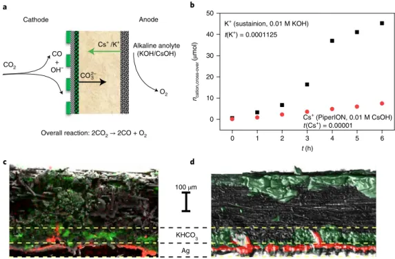
is available30,31. This precipitate forms because of the unintended cation cross-over through the AEM from the anolyte to the cathode (as verified by ion chromatography (Fig. 1b)), where it reacts with the CO2 feed and the electrogenerated OH−.
Scanning electron microscopy–energy-dispersive X-ray micro- analysis (SEM–EDX) and computed microtomography (micro-CT) studies revealed that precipitation occurs not only on the backside of the GDE (that is, in the gas flow channels), but also in its deeper regions (Fig. 1c). A compact layer of the precipitate was observed in the microporous layer and at the junction of the microporous and macroporous layers (see Supplementary Figs. 3–5, and discus- sion therein). This hampers CO2 from reaching the catalyst surface, explaining the continuously decreasing product formation rate (Supplementary Fig. 6).
The state-of-the-art method to overcome this issue is to rinse the cathode with water24,32,33. The performance of the cell, how- ever, cannot be fully restored using this method, as water can only wash the deposits from the backside of the GDE, and cannot pen- etrate the hydrophobic gas diffusion layer (GDL), unless excessive force (pressure) is applied. Such pressure would in turn damage the GDE structure, causing electrode flooding24,34. Decreasing the anolyte concentration extends the operation to prolonged times- cales. The cross-over of K+ or Cs+ ions (Fig. 1b), and the conse- quent precipitate formation and performance fading still occur (see Supplementary Fig. 6 and discussion therein). Increasing the humidity of the CO2 gas stream is another alternative mitigation strategy, but it changes the overall operation of the cell24,29. An elegant
solution to this problem would be to operate such electrolyser cells with pure water anolyte, inherently preventing precipitate forma- tion in the cathode GDE.
Operation of CO2 electrolysers with pure water anolyte Using pure water as anolyte instead of 0.1 M KOH the current density drops to one-third (100 mA cm−2 versus 300 mA cm−2; Supplementary Fig. 7a). This large difference appears also in the low frequency limit of the impedance spectra (Supplementary Fig.
7b), which is a measure of the derivative of the current–voltage curve. In contrast, the high frequency limits do not differ much, being around 1 Ω cm2 for both, which is comparable with the values reported for similar systems10,27. This value is related to the total cell resistance, including the membrane, the contribution of which to the total impedance spectra was found to be ohmic in our control experiments (Supplementary Note 2 and Supplementary Fig. 8).
The similarity in this value is not surprising, since the membrane conductance is mostly affected by the operational conditions and the charge-transporting ions35,36. Analysing the anode gas composi- tion and the complete mass balance of the process, CO32− was iden- tified as the majority charge carrier through the AEM, irrespective of the anolyte used (Supplementary Note 3 and Supplementary Fig.
9). The transference number of the cations remains in the range 10−4–10−5 for both Cs+ and K+, which practically excludes their con- tribution to the membrane conductivity (see Fig. 1b and related dis- cussion in Supplementary Note 4).
As both the membrane resistance and the charge carriers are the same in the two cases, the big difference in the currents with and without KOH in the anolyte must be attributed to changes at the cathode and/or anode interfaces. With pure water anolyte, two arcs can be observed on the impedance spectra (Supplementary Fig.
7b). In general, these are due to interfacial capacitances and charge transfer resistances on any of the electrodes; their exact origin is
0 1 2 3 4 5 6
0 10 20 30 40 50
KHCO3 Ag 100 µm CO2
O2 CO
+ OH–
Overall reaction: 2CO2 → 2CO + O2
CO2–3
Alkaline anolyte (KOH/CsOH)
Anode Cathode
Cs+ (PiperION, 0.01 M CsOH) t(Cs+) = 0.00001
K+ (sustainion, 0.01 M KOH) t(K+) = 0.0001125
ncation,cross-over (µmol)
t (h) Cs+ /K+
a b
d c
Fig. 1 | unintended cation cross-over and precipitate formation in alkaline anolyte-fed zero-gap CO2 electrolysers. a, Schematic illustration of the operation of an AEM-separated zero-gap CO2 electrolyser cell with alkaline anolyte. b, Ion-chromatographic quantification of K+ and Cs+ cross-over through different commercially available AEMs during CO2 electrolysis in a zero-gap electrolyser cell. c,d, Cross-section SEM–EDX (c) and micro-CT images (d) of a GDE after continuous CO2 electrolysis in a zero-gap cell (T = 50 °C, 1 M KOH anolyte, ΔU = 3.0 V). The red and green colours in the SEM–
EDX and micro-CT images represent Ag and K atoms, respectively. Experiments were repeated on separate cell assemblies independently three times, with similar results.
beyond the present scope of this study. Notably, the sum of the spans (‘diameters’) of these arcs is about three times larger when the cell is operated with pure water anolyte instead of 0.1 M KOH, indicating a higher total charge transfer resistance of the electrode processes.
Notably, in a zero-gap cell the effect of the membrane and the cata- lyst/ionomer layer cannot be fully separated. In all our analyses, we consider the ionomer and the catalyst/ionomer/membrane inter- faces to belong to the ‘catalyst’ and not to the membrane.
Activating the cathode catalyst by infusion with alkali cation-containing solutions
Considering the results of previous studies on the promoting effect of alkali cations in electrochemical CO2R37–44, cation permeation through the membrane from the anolyte might contribute to achiev- ing high reaction rates (this is absent in the case of water-based operation). In microfluidic electrolysers operating with liquid catholyte, alkali ions are inherently present around the cathode catalyst, which might (partly) explain why these systems outper- form their zero-gap counterparts in terms of the achievable current densities13,45. Furthermore, a long activation period (~60 min) was observed for zero-gap cells operated with dilute alkaline anolytes (Supplementary Fig. 10), indicating that cations slowly crossing the AEM (note the small transference number in Fig. 1b) and reaching the cathode surface have a boosting effect on the operation.
To validate this notion, we designed a process and an experimen- tal set-up allowing the injection of electrolyte solutions into the CO2
feed, which is, in turn, pushed through the cathode GDE by the gas stream (Fig. 2). This solution infusion method (referred to hereaf- ter as ‘regeneration’) allows the efficient removal of the precipitate potentially formed in the GDE (Fig. 1c), and also introduces alkali metal cations to the cathode (referred to hereafter as ‘activation’).
Repeatedly performing the activation, each new portion of the solution dissolves any precipitate from the GDE that is incidentally formed in/after the previous activations. During the solution infu- sion, the CO2 gas feed pushes the ‘solution plug’ through the cell, and therefore there is only a limited contact area between the solu- tion and the gas where precipitate might form in situ. This leads to a constant presence of the activating ions at the cathode GDE, but avoids accumulation.
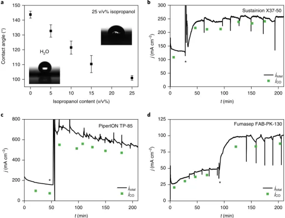
To enable the electrolyte solution to reach the catalyst layer, the composition of the solvent mixture must be tailored to the wetting properties of the GDE. Contact angles were determined for a series of solvent mixtures (Fig. 3a). As the GDL in our case is a hydro- phobic carbon paper, a solvent mixture of 25 v/v% isopropanol in water was employed for further studies. This wets the GDE properly without dissolving its polytetrafluoroethylene (PTFE) content or damaging the AEM (at least within the studied timeframe), and it dissolves the studied salts.
Upon activating the cathode GDE with 10 cm3 (approximately 50 times the free volume of the cathode compartment) of 0.5 M KOH solution, and meanwhile operating the electrolyser cell with pure water anolyte, a threefold increase in the CO formation rate (jCO) was observed (Fig. 3b–d). For the PiperION membrane (Fig.
3c), jco = 500–550 mA cm−2 represents higher current density than the state-of-the-art water anolyte-operated CO2 electrolyser cell27. The current does not drop after the activating solution leaves the cell, but remains relatively stable, with a slow decay (discussed later). Importantly, this effect was very similar for three commer- cial membranes (Sustainion X37-50, PiperION TP-85, Fumasep FAB-PK-130) of very diverse chemical composition, thickness, etc.
Except for a short transient period, the CO formation selectivity does not drop upon excess liquid injection in the cathode compartment, and it even increases for Sustainion (Fig. 3b, from 70 to 85% FE) and PiperION (Fig. 3c, from 55 to 85% FE) membrane-containing cells.
For comparison, we performed similar activation experiments with pure aqueous solutions (that is, no isopropanol content). A less pronounced activation was seen, albeit with very large variance (Supplementary Fig. 11). This is rooted in the hydrophobicity of the GDE, which only allows the aqueous activation solution to reach the catalyst surface if numerous imperfections (for example, cracks) are present in the structure. Again, tailoring the solvent mixture is crucial for wetting the deeper regions of the GDE without damaging its structure.
Another important aspect is the necessity of the electric field during the activation: if we inject the activation solution without polarization and start the electrolysis subsequently, there is only a minor current increase. This indicates that, beyond simple physical interactions, electrosorption of the cations on the negatively polar- ized Ag catalyst particles might be a major contributor.
Mechanism of the activation process
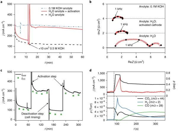
Performing the cathode activation on the water-fed cell increases the current to a level almost identical to that measured with 0.1 M KOH anolyte (Fig. 4a). While the high-frequency impedance of the water-fed cell remains unchanged, the gross charge transfer resis- tance decreases to a similar value to that detected with alkaline ano- lyte (Fig. 4b and Supplementary Fig. 12, with further discussion in Supplementary Note 5). As the same anode catalyst (IrOx) is rou- tinely employed in proton-exchange membrane water electrolysers at high current densities (1–3 A cm−2)46, it is reasonable to assume
Mass flow controller
Binary gas analyser CO2 in O2
66.7%
Heat exchanger H2O Power supply
Cathode
Anode
Gas chromatograph
IO Pump
I (A)
2.75 V 1.50 A OI
Mass spectrometer P
93 sccm Flow meter 1.
CO2
2.
CO2
CO2 CO2
CO2
t (h)
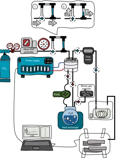
Fig. 2 | Schematic piping and instrumentation diagram of the test framework employed. In the inset (top), ‘1’ shows the default positions of the manual valves, forming a continuous gas path to the cell and bypassing the activation loop. Turning the valves into position ‘2’, the gas is driven through the activation loop, carrying the activation fluid into the cell.
that this difference is mostly related to the cathode catalyst. To safely exclude the contribution of the anode process (Supplementary Note 6), we have recorded polarization curves of IrOx/PiperION ionomer layers in different electrolyte solutions (that is, NaOH, KOH, CsOH;
Supplementary Fig. 13a). The polarization curves overlap, showing that the electroactivity of IrOx is not affected by these cations detect- ably. This confirms that the eventual penetration of small amounts of the activation solution to the anode side cannot be responsible for the enhanced performance.
The activation is fully reversible: rinsing the cathode GDE with an isopropanol/water mixture (without any dissolved electrolyte) in the absence of polarization restores the current to its initial low value within 1 min, which can be increased again by repeating the activation (Fig. 4c). This repeatable instantaneous activation–
deactivation further suggests that the performance enhancement is mostly related to the change in the cathode reaction kinetics.
If the electrolyte penetration to the anode side (upon activation) were a major contributor, a single rinsing of the cathode side could not have such a rapid effect. Additional control experiments were carried out without anolyte recirculation, to avoid the possible accumulation of cations or change in the pH. The activation phe- nomenon occurred in these cases as well (Supplementary Fig. 13b).
All these observations together imply that the activation mostly affects the cathode interface.
To take a closer look at processes occurring during activation, we followed the product stream composition in quasi-real time via mass spectrometry, while also monitoring the pressure in the CO2
inlet piping (Fig. 4d). The pressure trace shows that it takes about 50 seconds for the activating solution to leave the cell (indicated by a rapid pressure drop after the initial increase). While the cathode compartment is filled with the activation fluid it is deprived of CO2, resulting in high H2 formation rate and decreased CO2 and CO partial pressures in the product gas stream (lower panel of Fig. 4d). When the liquid leaves the cell, the CO partial pressure (hence jCO) immediately increases, and meanwhile the H2 concen- tration decreases. Both stabilize in 2 minutes after the activation, demonstrating that the activation is instantaneous (and there- fore related to the cathode GDE and its interface with the AEM).
Finally, the activated state does not diminish rapidly, which would be expected if entrapped cations leaving the AEM were mostly responsible for the activation, as their amount could only be finite in the thin membranes.
Factors determining the efficiency of the cathode activation
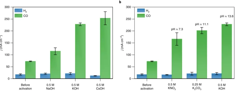
The activation process influences the pH and ionic strength at the cathode (at least temporarily), and the infused ions can also adsorb onto the catalyst surface. To separate the effects of these parameters, we performed two sets of experiments: one in which different alkali metal hydroxides (that is, different cations) were employed (Fig.
5a and Supplementary Fig. 14a,c), and another in which solutions with constant K+ concentration, but with different anions, were injected (Fig. 5b and Supplementary Fig. 14b,d). The activation becomes more pronounced in the order NaOH << KOH < CsOH,
0 5 10 15 20 25
100 110 120 130 140 150
0 50 100 150 200
0 50 100 150 200 250 300
0 50 100 150 200
0 200 400 600 800
0 50 100 150 200
0 25 50 75 100
c d 125
b
Contact angle (°)
Isopropanol content (v/v%)
*
j (mA cm–2)
t (min)
jtotal jCO
a
H2O
25 v/v% isopropanol
Fumasep FAB-PK-130 PiperION TP-85
Sustainion X37-50
*
t (min) t (min)
*
j (mA cm–2) j (mA cm–2)
jtotal jCO jtotal
jCO
Fig. 3 | Cathode activation using different commercially available AEMs. a, Contact angles of different water/isopropanol solvent mixtures on the microporous side of a Sigracet 39BC GDL. b–d, Chronoamperometric curves and CO formation partial current densities (Tcathode = 60 °C, 12.5 cm3 cm−2 min−1 CO2 feed rate, pure water anolyte) measured using Sustainion X37-50 (ΔU = 3.1 V) (b), PTFE-reinforced 15-μm thick PiperION TP-85 (ΔU = 3.2 V) and Fumasep FAB-PK-130 (ΔU = 3.1 V) AEMs (c). Solutions of 10 cm3 of 0.5 M KOH (for b and d) or 0.5 M CsOH (c) in 1:3 isopropanol/water mixture were used to activate the cathode at the times marked with asterisks in the figures. Experiments were repeated on separate cell assemblies independently at least three times, with similar results. The values in a are the mean value of three independent measurements, together with the calculated standard deviations.
whether considering the jCO values (Fig. 5a), the onset voltage or the slope of the linear sweep voltammetry curves (Supplementary Fig. 14a) or the decrease in the arc diameter in the impedance spec- tra (Supplementary Fig. 14c). As the pH and ionic strength of these solutions are identical, these measurements directly prove the pro- moting effect of K+ and Cs+ ions, and the less considerable effect of Na+ ions in the electrochemical CO2R, in accordance with theoreti- cal37,41,42 and experimental results38–40,43,44. The same trend was found when operating the same cell with NaOH, KOH and CsOH anolytes (Supplementary Fig. 15).
To investigate the effect of the local pH change caused by the acti- vation, solutions of different potassium salts were infused. Although some differences can be seen, they are less striking compared to the case of different cations (Fig. 5b and Supplementary Fig. 14b,d). The current density increase followed the order KNO3< K2CO3< KOH, suggesting that the effect of the local pH during the activation can- not be fully ruled out. The same trend was found for the double-layer capacitance of the catalyst/ionomer layer studied in the solution of these salts (Supplementary Fig. 16). These differences might stem from the pH-dependent structure of the ionomer (it is a polyelectro- lyte) or from the differences in the double-layer structure (and there- fore the specific capacitance) in the different solutions. In any case, this can affect the cation adsorption process during the transient period of infusion, and, in turn, the amount of adsorbed alkali metal cations.
The activation efficiency scales with the concentration (up to 0.5 M, Supplementary Fig. 17) and volume (up to 2 cm3, Supplementary Fig. 18) of the electrolyte solution. Finally, the
membrane and gross interfacial charge transfer resistance decreases continuously with the increasing temperature (Supplementary Fig.
19), indicating room for further performance enhancement through careful process engineering.
Long-term operation
Long-term electrolysis with pure water feed at the anode was per- formed with a PiperION membrane-containing cell for 224 hours (Fig. 6a,b). Meanwhile the cathode was activated with 5 cm3 of 1.0 M CsOH solution after every 12 hours. The initial (before activation) measured jCO ≈ 120 mA cm−2 increased to jCO ≈ 350 mA cm−2 after the first activation. This increased further when the activation was repeated after 24 and 36 hours, and subsequently it remained sta- ble at jCO= 420 ± 50 mA cm−2 (with ~90% FECO) for over 200 hours (eight days) of continuous operation. The regular spikes on the chronoamperometric curve (every 12 hours) belong to the activa- tion processes (Fig. 6a), while the initial spikes (in the first 25 hours) represent irregular water release from the cell. Clearly, there is an initial period when the water management of the cell stabilizes. The FECO first decreases during the activation steps, as the large transient current is associated with the increased H2 evolution (see also Fig.
4d). FECO is then restored (or even increased), while jCO increases compared to its value before activation. The single-pass conver- sion was calculated to be 23% (see calculations in Supplementary Note 7), about 11 times larger that of the reported state-of-the-art water-based CO2 electrolyser27. A similar experiment was performed with the Sustainion X37-50 membrane, where the electrolyser
0 10 20 30 40 50 60
100 200 300 400 500
0 2 4 6 8
0 2 4 6
100 200 300
0 1 × 10⁻⁵ 6 × 10⁻⁶ 4 × 10⁻⁶ 2 × 10⁻⁶ 8 × 10⁻⁶
Deactivation step (cell rinsing)
1 kHz
1 kHz
Anolyte: H2O 1 kHz
Anolyte: H2O;
activated cathode Anolyte: 0.1M KOH
Activation step
ReZ (Ω cm2) -ImZ (Ω cm2)
t (min)
0.1M KOH anolyte H2O anolyte + activation H2O anolyte
+10 cm3 0.5 M KOH
0 60 120 180 240 300
0 100 200 300 400
500 jtotal
jCO
t (min)
0 500 1,000 1,500
j (mA cm–2)
a b
d c
0 0.2 0.4 0.6 0.8
p (bar)
p (Torr)
t (s)
CO2 (m/z = 44) H2 (m/z = 2) CO (m/z = 28) j (mA cm–2)j (mA cm–2)
Fig. 4 | Mechanism and reversibility of cathode activation. a,b, Chronoamperometric curves (a) and EIS spectra (b) recorded before and after activating the cathode GDE with 10 cm3 of 0.5 M KOH solution in 1:3 isopropanol/water mixture (Sustainion membrane. ΔU = 3.1 V, Tcathode = 60 °C, 12.5 cm3 cm−2 min−1 CO2 feed rate). reZ and ImZ denote the real and imaginary compontents of the impedance (Z). c, Chronoamperometric curve and CO formation partial current density measured under identical conditions as in a. The cathode GDE was activated at the marked times with 10 cm3 of 0.5 M KOH solution in 1:3 isopropanol/water mixture, while it was rinsed with 10 cm3 of 1:3 isopropanol/water mixture to deactivate it. d, Time-resolved current density and product stream composition change during, and immediately after, activating the electrolyser cell (with 3 cm3 of 1 M CsOH solution in 1:3 isopropanol/water mixture, ΔU = 3.2 V, Tcathode = 60 °C, 12.5 cm3 cm−2 min−1 CO2, PiperION membrane). In the upper panel, the pressure in the CO2 inlet pipe during activation is indicated. Experiments were repeated on separate cell assemblies independently at least three times, with similar results.
was operated for 10 hours. After activation, the jCO increased from 120 mA cm−2 to 220 mA cm−2, which has not changed in the first five hours, followed by a slight decrease to jCO ≈ 200 mA cm−2 (Supplementary Fig. 20).
Importantly, no physical precipitate formation was observed in the cells, which were activated repeatedly (see an example for a cell operated for over 100 hours in Supplementary Note 8 and Supplementary Fig. 21). The lack of precipitate formation is attrib- uted to the inherent nature of the activation process, where the applied solvent mixture can dissolve and remove the previously formed precipitate crystals. Therefore, while a small amount of alkali cations is present after the activation, no accumulation occurs.
The presence of cations in the cathode GDE can also be ensured by other methods. For example, controlled cross-over from the ano- lyte can provide the proper amount of alkali cations to the cathode, especially if combined with periodic regeneration of the cathode with the proper solvent mixture (Supplementary Fig. 6). As a fur- ther example, the Ag catalyst layer can be deposited from alkali metal ion-containing suspensions. In this way, the promoter ions are inherently present on the catalyst surface and within the iono- mer layer. The electrochemical performance and impedance spec- trum of the electrolyser cell assembled with this catalyst layer, and operated with water anolyte, are similar to those of the activated cells, presented previously. The performance, however, decreased
Before activation
0.5 M NaOH
0.5 M KOH
0.5 M CsOH 0
50 100 150 200 250 300
H2 CO
Before activation
0.5 M KNO3
0.25 M
K2CO3 0.5 M KOH 0
50 100 150 200 250 300
H2
CO pH ≈ 13.6
pH ≈ 11.1 pH ≈ 7.3
j (mA cm–2)
a b
j (mA cm–2)
Fig. 5 | Deconvolution of the complex effect of the activating electrolyte. a,b, Partial current densities for CO and H2 production during constant-voltage electrolysis with water anolyte, after cathode activation using 10 cm3 solution (in 1:3 isopropanol/water mixture) of different alkali metal hydroxides (c = 0.5 M) (a) and different potassium salts (c(K+) = 0.5 M) (b). The cell was operated at ΔU = 3.1 V, Tcathode = 60 °C with 12.5 cm3 cm−2 min−1 CO2 feed rate, using a Sustainion membrane in the cell. The plotted values are the mean from three gas composition measurements (gas chromatography analysis), together with the calculated standard deviations. All experiments were repeated independently on separate cell assemblies three times, with similar results.
0 50 100 150 200
0 300 600 900 1,200
0 50 100 150 200
0 100 200 300 400
500 H2
CO
t (h) t (h)
j (mA cm–2)
a b
j (mA cm–2)
Fig. 6 | Long-term operation of a CO2 electrolyser with water anolyte and periodic activation. a,b, Total current density (a) and CO and H2 partial current densities (b) during constant-voltage electrolysis, using a PTFE-reinforced 15-μm thick PiperION TP-85 membrane-separated cell (ΔU = 3.2 V, T = 60 °C water anolyte, 12.5 cm3 cm−2 min−1 CO2 feed rate). The cathode was activated with 5 cm3 of 1 M CsOH solution in 1:3 isopropanol/water mixture after every 12 h of the electrolysis. Long-term experiments (over 100 h) were repeated on separate cell assemblies independently five times, with similar results.
with time, as the K+ ions gradually leached out from the catalyst layer (Supplementary Fig. 22).
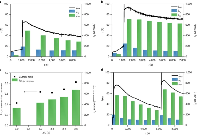
Operating larger cells and cell stacks with water anolyte The scalability of the cathode activation approach was demon- strated on a cell having an active surface area of 100 cm2, and on a three-layer electrolyser stack formed therefrom (Fig. 7 and Supplementary Fig. 23). The cathode activation boosted the jCO in all experiments, and jCO also increased gradually with the applied cell voltage (Fig. 7a–c). Importantly, jCO = 450 mA cm−2 was mea- sured at ΔU = 3.2 V (Fig. 7c), which rivals the results recorded on our smaller cell (Figs. 3c and 6). This value further increased to jCO = 650 mA cm−2 at ΔU = 3.5 V (Fig. 7b), which is close to the best value measured in the same electrolyser cell using 0.1 M CsOH anolyte10. Importantly, the rate of the current decay after the activa- tion decreased with the increasing cell voltage (that is, the effect of activation lasts longer at higher cell voltages (Fig. 7c)). This again confirms that the activation occurs via the electrosorption of the cations at the negatively polarized cathode.
The activation was also performed in a three-cell stack at ΔU = 9.9 V stack voltage (Fig. 7d), translating to ΔU = 3.3 V cell volt- age for comparability with the single cell. The activation increased jCO to over 500 mA cm−2, a current density even slightly higher than that measured in the single-layer cell (Fig. 7a). One key challenge
during scale-up is the increased resistance of the cell (stack) against the flow of gas and the activation fluid during infusion. Therefore, we have monitored the pressure build-up on the cell (cell stack). It was indeed higher than in the case of the small cell (0.8 bar for the small cell, ~2 bar for the large cell and ~3 bar for the cell stack, see Supplementary Fig. 22), but not detrimental at all. Finally, the cell design was not optimized for this activation process, leaving a lot of room for improvement. In this regard, scale-up and optimization of such electrolyser stacks are ongoing (see Supplementary Fig. 23 for a stack of size 1,000 cm2 per cell).
Conclusions
We uncovered some microscopic/mechanistic reasons behind the performance fading in zero-gap CO2 electrolyser cells. SEM–EDX and micro-CT analysis confirmed the formation of alkali metal bicarbonate and mixed carbonate–bicarbonate precipitate plaques within the cathode GDE of cells operating with alkaline anolyte, hindering CO2 gas from reaching the catalyst surface. In an appar- ent contradiction to this, we identified the presence of alkali metal ions on the cathode catalyst surface to be a major contributor for high current density CO2 reduction. To overcome this ambiguity, we developed an operando activation method, where the cathode of pure water anolyte-fed CO2 electrolyser cell is infused periodi- cally with different alkali cation-containing solutions with proper
0 1,000 2,000 3,000 4,000 5,000 6,000 0 200 400 600 800 1,000 jtotal jH
2
jCO
jtotal jH
2
jCO j (mA cm–2)jCO, t = 10 minutes(mA cm–2)
0 20 40 60 80 100
t (s)
I (A)
0 1,000 2,000 3,000 4,000 5,000 6,000 7,000 0 200 400 600 800 1,000
t (s) 0
20 40 60 80 100
I (A)
3.0 3.1 3.2 3.3 3.4 3.5
0.0 0.2 0.4 0.6 0.8 1.0
∆U (V) Current ratio
a
c d
b
0 200 400 600 800 1,000
jCO, t = 90 minutes/jCO, t = 10 minutes
0 2,000 4,000 6,000 8,000
0 200 400 600 800 1,000
0 20 40 60 80 100
t (s)
I (A) j (mA cm–2)j (mA cm–2)
jtotal jH
2
jCO jCO, t = 10 minutes
Fig. 7 | Cathode activation experiments in larger electrolyser cells and stack. a,b, Chronoamperometric measurements on a single-layer electrolyser cell of area A = 100 cm2 (T = 60 °C, water anolyte, 12.5 cm3 cm−2 min−1 CO2 feed) at ΔU = 3.3 V (a) and ΔU = 3.5 V (b). c, CO partial current densities 10 min after performing the cathode activation (20 cm3 of 1 M CsOH solution in 1:3 isopropanol/water mixture) and the ratio of CO formation partial current densities 90 and 10 min after performing the cathode activation, recorded at different cell voltages. d, Chronoamperometric measurement on a three-layer electrolyser cell stack of A = 100 cm2 (T = 60 °C, water anolyte, 12.5 cm3 cm−2 min−1 CO2 feed, cathode activation with 60 cm3 of 1 M CsOH solution in 1:3 isopropanol/water mixture) at ΔU = 9.9 V. Experiments were repeated on separate cell assemblies independently three times, with similar results.
wetting properties. We have shown that the activation predomi- nantly affects the cathode chemistry and has negligible effect on the anode process and the AEM properties.
The presented proof-of-concept demonstrates scalable water-fed electrolyser cells operating at CO2 reduction rates match- ing those using alkaline electrolytes (jCO of 420 ± 50 mA cm−2) over prolonged times (over 200 hours). The activation is repeatable, implying that the observed slow current decrease over time is not caused by any degradation mechanism, but by the continu- ous desorption and leaching of the alkali cations from the cath- ode catalyst layer during operation. The rate of performance decay depends on the cathode GDE composition (for example, ionomer composition and content, thickness and porosity) and on opera- tional parameters, such as humidification of the CO2 stream, water cross-over through the membrane, cell voltage, temperature, cur- rent density, etc. Optimizing these parameters is a major engineer- ing task, which in turn might bring a big reward: the ability to operate zero-gap CO2 electrolyser cells with pure water anolyte at high current density, with negligible maintenance requirements.
Such studies are in progress in our laboratory, together with fur- ther scaling-up of the technology.
Methods
Materials. All chemicals were purchased from commercial suppliers (Sigma-Aldrich, VWR International), and were of at least analytical grade and were used without further purification. MilliQ grade (ρ = 18.2 MΩ cm) ultrapure deionized water was used to prepare all the solutions.
Electrode preparation. Silver nanoparticles (davg < 100 nm, Sigma-Aldrich) were dispersed in a 1:1 isopropanol/water mixture at a concentration of 25 mg cm–3, together with 15 wt% ionomer, matching the membrane used (Sustainion XA-9, Fumion FAA-3, PiperION I-46). As for the anode catalyst, IrOx nanoparticles (Fuel-Cell Store) were dispersed in an identical solvent mixture and ionomer concentration, but with a concentration of 20 mg cm−3. The IrOx dispersion was homogenized in a regular ultrasonic bath for 20 min (keeping the bath temperature below 35 °C), while a high-power immersion sonotrode was used to disperse the Ag nanoparticles.
The Ag dispersion was spray-coated on Sigracet 39BC carbon GDLs preheated on a hotplate at 100 °C, using a hand-held airbrush and compressed air carrier gas (~100 cm3 min−1). The anode catalyst was spray-coated similarly, on a porous titanium frit. The cathode catalyst loading was 1.0 ± 0.1 mg cm−2 for the measurements with the PiperION membrane, and it was 3.0 ± 0.1 mg cm−2 for the other systems, while the anode catalyst amount was 1.0 ± 0.1 mg cm−2.
Commercially available AEMs were used to separate the anode and the cathode chambers (Class T X37-50 Sustainion (50-μm thickness) from Dioxide Materials; Fumasep FAB-PK-130 (130-μm thickness) from FUMATECH BWT;
PTFE-reinforced 15-μm thick PiperION TP-85 from W7energy). The membranes were ion-exchanged before use for 24 hours in the respective 1 M alkaline solution (NaOH/KOH/CsOH), which was exchanged to a fresh solution after the first 5 hours.
Zero-gap electrolyser cells. All experiments presented in this paper were performed in zero-gap electrolyser cells. These consist of (from bottom to top in Supplementary Fig. 1): an anode current collector on which an anolyte flow pattern was formed, a porous Ti frit with catalyst layer on its side in direct contact with the AEM, held in place by a spacer element, an AEM (different membranes were used in our measurements, as described in the manuscript), a GDE with its catalyst layer facing the membrane, a spacer element to set the compression ratio of the GDE and a cathode current collector with a concentric flow pattern with a central inlet, and an outlet on the perimeter of the flow pattern. The electrolyser elements were assembled directly on top of each other and were held together by six bolt screws (3 Nm torque was applied). The active surface is circular, of diameter 3.2 cm, resulting in a geometrical surface of area, A = 8 cm2, the value of which was used to normalize the current values reported here. A larger (A = 100 cm2) cell was also used to demonstrate the scalability of our approach. The design of this cell is very similar to its smaller counterpart, but instead of being spherical, it is rectangular in shape. A stack containing three cells was connected in series electrically and in parallel with regards to gas distribution10,24.
Test framework. The test framework (Fig. 2) was based on our previously reported experimental set-up24. Briefly, the CO2 feed rate was controlled with a Bronkhorst F-201C type mass-flow controller, while an Agilent ADM flow meter was used to measure the flow rate of the gas outlet. The accuracy of this measurement was confirmed by repeating these measurements with the classical bubble-soap method periodically. The gas flow rate was normalized with the surface area of
the cell (hence the units of cm3 cm−2 min−1). The CO2 gas was passed through a temperature-controlled humidifier before entering the cell. An extra loop was inserted before the electrolyser to be able to inject electrolyte solutions into the gas stream. This activation loop can be bypassed by turning two three-way valves. After filling the loop with the respective electrolyte solution, it can be injected into the gas stream by turning these two valves. The pressure of the CO2
in the electrolyser was measured using a digital pressure gauge. The anolyte was circulated in the anode compartment using a peristaltic pump. The electrochemical measurements were performed using a Biologic VMP-300 type instrument, equipped with electrochemical impedance spectroscopy (EIS)- and high current (up to 10 A) booster options. All the experiments presented here (including the EIS measurements) were performed using the potentiostat with the booster connected.
For the measurements with the larger electrolyser cell and stack, a programmable power supply (TDK-Lambda GEN-15-220) was used.
The measurements were conducted in a two-electrode set-up, and the total cell voltage is given as the voltage difference between the anode and the cathode (hence the positive values). The absolute value of the current/current density is shown (positive values) in all figures. No IR correction was applied on the voltage values presented throughout the manuscript. EIS spectra have been taken at constant cell voltage with added 10 mV r.m.s. perturbation in the frequency range 100 kHz down to 0.1 Hz, with 10 points per frequency decade. The self-consistency of the EIS data was checked by performing Kramers–Kronig tests. Impedance spectra are presented in the form of complex-plane plots (‘Nyquist plots’) where the points of f = 10k Hz frequencies (where k is an integer, −1 ≤ k ≤ 5) are marked. To help in distinguishing spectra they are shifted along the ordinate.
The composition of the cathode product stream was analysed using a Shimadzu GC-2010 Plus type instrument, equipped with a barrier discharge ionization (BID) detector. A Restek ShinCarbon ST column was employed for the separation with 6.0 grade helium carrier gas. An automatized six-port valve was used to take samples at regular time intervals. In certain experiments the product stream composition was simultaneously monitored using an m/z analyser (SRS UGA200) equipped with an atmospheric sampling capillary. This technique allowed the quasi-real-time determination of the product composition, hence providing time-resolved information on the processes occurring during and immediately after cathode activation. The anode gas composition was analysed with a BGA-244 type Binary Gas Analyser (Stanford Research Systems), to monitor the CO2/O2 ratio.
Membrane impedance measurements. A Zahner Im6e type instrument was used to characterize the membrane impedance in a four-electrode cell (Supplementary Fig. 8a). The EIS spectra were recorded in galvanostatic mode (I = 0), with 1 mA perturbation amplitude, from 100 kHz to 1 Hz, recording twice 8 points per decade.
Contact angle measurements. An EasyDrop (Krüss) type instrument was used to measure the wetting properties (that is, contact angles) of different solvent mixtures on the microporous side of the Sigracet 39BC GDL used. A drop of the solvent mixture was formed on the plate with the use of a syringe. Using the CCD camera of the goniometer, the drop contour of the captured photographs was analysed.
X-ray micro-computed tomography analysis. A Bruker SkyScan 2211 Multiscale X-ray Nanotomograph (Bruker) instrument was used to record micro-CT images.
The three-dimensional structure of the samples was scanned using an 11- megapixel CCD detector by applying a source voltage of 70 kV and current of 400 μA (in microfocus mode, with a resolution of 1 μm per pixel). NRecon reconstruction software (Skyscan, Bruker) was used to reconstruct the projected images, while the CTAn and CTVox software (Skyscan, Bruker) were applied to carry out the image segmentation and visualizing the 3D-rendered objects, respectively.
SEM–EDX analysis. A Hitachi S-4700 scanning electron microscope (SEM) coupled with a Röntec EDX detector was used to take images of the GDEs. The microscope was operated at 10 kV acceleration voltage.
X-ray diffraction measurements. X-ray diffraction patterns were obtained using a Bruker D8 ADVANCE X-ray diffractometer, applying CuKα (λ = 1.5418 Å) radiation. Rietveld refinement was carried out to quantify the phase composition of the obtained materials.
Ion chromatography measurements. To gain direct proof on the K+ and Cs+ cross-over through the AEM, electrolysis experiments were performed with 0.01 M KOH and 0.01 M CsOH anolytes at 60 °C, and the humid gas leaving the cell was collected in a mechanical liquid/gas separator, initially filled with 10 cm3 of pure water. The K+ or Cs+ concentration of the fluid in this water separator was then monitored during electrolysis by using ion chromatography (Fig.
1b). All ion chromatography measurements were performed using a Shimadzu ion-chromatographic system, consisting of a high pressure chromatographic module (LC-20AD SP), an eluent degas module (DGU-20A5R), an autosampler (SIL-20AC), a conductivity detector for non-suppressed conductivity measurements (CDD-10A VP), a column oven to maintain constant 40 °C temperature (CTO- 20AC) and a Shodex IC YS-50 column. Methanesulfonic acid (4 mM) was used as eluent with a flow rate of 1.0 cm3 min−1, and the sample volume was 50 μl.