Article
Calcium Phosphate Based Bioactive Ceramic Layers on Implant Materials Preparation, Properties, and Biological Performance
Monika Furko * and Csaba Balázsi
Institute for Technical Physics and Materials Science, Centre for Energy Research, Konkoly-Thege Str. 29–33, H-1121 Budapest, Hungary; balazsi.csaba@energia.mta.hu
* Correspondence: furko.monika@energia.mta.hu
Received: 11 August 2020; Accepted: 22 August 2020; Published: 25 August 2020 Abstract:Calcium phosphate based bioactive ceramics (CPCs) can be successfully applied as implant coatings since they are chemically similar to the inorganic constituent of hard tissues (bones, teeth).
Nowadays, in orthopedic surgeries, it is still common to use metallic implants. However, the biological response of the human body to these foreign materials can be adverse, causing the failure of implant materials. This disadvantage can be avoided by bioactive coatings on the surface of implants. CPCs can be prepared by different routes that provide coatings of different quality and properties. In our paper, we compared the morphological, chemical, and biological properties of CPC coatings prepared by the pulse current electrochemical method. The size and thickness of the pulse current deposited platelets largely depended on the applied parameters such as the length ofton
and the current density. The decrease in theton/toffratio resulted in thinner, more oriented platelets, while the increase in current density caused a significant decrease in grain size. The higher pH value and the heat treatment favored the phase transformation of CPCs from monetite to hydroxyapatite.
The contact angle measurements showed increased hydrophilicity of the CPC sample as well as better biocompatibility compared to the uncoated implant material.
Keywords: bioceramics; calcium phosphates; bioactive coatings; pulse current deposition; corrosion
1. Introduction
In orthopedic surgeries, the key issues are medical implant materials. The main demands for these materials are mechanical and chemical stability as well as high strength and toughness [1] Moreover, metallic implants need to be non-toxic, non-immunogenic, non-thrombogenic, and non-carcinogenic [2].
In this respect, titanium and its alloys are the preferred materials due to their optimal load-bearing properties [3]. The metallic bone implants are recognized by human tissues as a foreign body [4,5].
For this reason, these implants might be rejected by the human body even if they are considered to be bioinert [6]. Another problem with metallic implants is that they might release toxic metal ions (Cr3+, Al3+, Mo2+, Co2+) after long-term contact with body fluids. It has been confirmed that the degradation of the implants due to corrosion or mechanical stress increases the amount of dissolved metals and particles that might lead to the failure of implants [7]. Atapour et al. [8] investigated the corrosion behavior and ion release of selective laser melted (SLM) AISI (American Iron and Steel Industry) 316L stainless steel samples in a protein-rich artificial body fluid at pH 7.3 and in diluted hydrochloric acid (HCl) at pH 1.5. Their research work revealed that the SLM 316L sample released slightly less Fe, Cr, and Ni ions compared to the wrought 316L sample and the heat treatment also decreased the released metallic ions. The dissolved metallic ions and the dissoluble metallic oxide particles can also cause metallosis, when these particles agglomerate or accumulate in a specific
Coatings2020,10, 823; doi:10.3390/coatings10090823 www.mdpi.com/journal/coatings
organ. This might result in adverse medical conditions and can cause several diseases such as allergy, inflammation, carcinogenicity, and hypersensitivity [8]. Metal ions affect the osteoblast proliferation, cell viability, and collagen-I expression in a different rate and way. These ions can be ranked (from the lowest to the highest toxicity) as follows: Na<Cr<Mg<Mo<Al<Ta<Co<Ni<Fe<Cu<
Mn<V [9,10]. Therefore, there are still enormous efforts to develop appropriate coatings in order to decrease the possibility of the rejection of implant materials by the human body. For biomedical applications, the ceramic layers and ceramic oxides can be obtained by several techniques. The most commonly applied methods are sol–gel [11,12], glow-arc discharge [13], dip-coating [14], plasma spraying [15–17], chemical vapor deposition (CVD) [18], pulsed laser deposition (PLD) [19], and electrochemical deposition [20,21]. The main advantages of applying electrochemical deposition over the physical deposition methods are that it is cost effective, the working temperature is low, the preparation parameters can be easily controlled and altered, and a homogenous layer can be deposited on 3D materials with complex geometry [22]. The most intensively and widely investigated bioactive coatings that are able to enhance bone cell growth are calcium phosphate based bioactive ceramics (CPCs) [23–25]. A material can be regarded as bioactive if it induces specific biological activity [26].
The CPCs are exceptionally biocompatible and bioactive due to the formation of a strong bond between the hard tissue and implant material due to its chemical similarity to the biological calcified tissue.
Moreover, CPCs have been shown to stimulate osteo-conduction and can be integrated into bone without triggering any immune reaction [27]. The biological response to CPC coated implants is strongly affected by its properties [28–31]. CPCs have a wide range of potential applications such as in drug delivery systems [32], in bone tissue engineering [19,33,34], in orthopedic and dental implantation [9,11,35], and. This paper aims to summarize and compare the characteristics of the coating prepared by pulsed electrochemical deposition (ED).
2. Materials and Methods
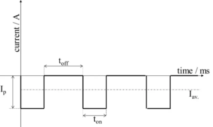
The electrochemical deposition process was performed by pulse current. The electrolyte used for the electrodeposition process of calcium phosphate based bioactive ceramic (CPCs) consisted of 0.49 M Ca(NO3)2·4H2O, 0.29 M NH4H2PO4, and 10 mL/l H2O2. The pH of the solution was kept between 4.0 and 4.5. The schematic illustration of the applied square wave form can be seen in Figure1.
Figure 1.Cathodic square wave current impulses.
In all of our experiments, the pulse current deposition was performed in a two-electrode cell set-up where the anode was a platinum sheet and the cathode was the metallic implant disc. During the deposition, the temperature was kept at 70◦C and the deposition time was 10 min. The deposition parameters varied with regard to the appliedtonandtofftimes as well as the peak current densities and surface post-treatment as indicated in Table1. Titanium alloy (Ti6Al4V) discs (19 mm in diameter, and 1 mm in thickness) were used as substrates. One side of each substrate was sandblasted by applying a standard commercial procedure.
Table 1.Preparation parameters of the electrodeposited CPC coatings.
Deposition Parameters Samples
S1 S2 S3 S4 S5
ton/ms 5 5 1 1 1
toff/ms 5 5 10 10 10
ip/A·cm−2 0.4 1 5 5 5
Surface treatment after
deposition - - -
1 M NaOH solution, 70◦C for 2 h
Heat treatment at 900◦C for 30 min
Scanning Electron Microscopy/Energy-dispersive X-ray spectroscopy (SEM/EDX, Hitachi SU8230, Jeol 8230, Hitachi Group, Tokyo, Japan) and Transmission Electron Microscopy (TEM, FEI Tecnai TF2, Thermo Fisher Scientific, Waltham, MA, USA) devices were used for morphological investigation of the layers.
Fourier-transform infrared spectroscopy (FTIR) spectra were recorded with a Bruker Vertex 70 FTIR spectrometer coupled with Hyperion 2000 IR microscope (Bruker, Wien, Austria) by the specular reflection technique, over the 4000–400 cm−1wave number range at room temperature. Number of scans: 128 scans; resolution: 2 cm−1.
X-ray diffraction measurements were performed to analyze the crystal structures of the samples.
The diffractograms were recorded with a Bruker AXSD8 Discover diffractometer (Cu Kαradiation source, with Göbel mirror and GADDS 2D detector system at 40 kV and 40 mA). The diffraction patterns were collected over a 2θrange from 10◦to 80◦with a 1◦/min rate.
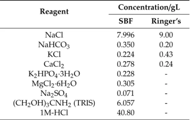
Zahner IM6e electrochemical equipment (Zahner, Kronach, Germany) was applied for potentiodynamic polarization studies. For electrochemical characterizations, a conventional three-electrode cell set-up was used. The working electrode was a metallic implant disc with and without coatings, the counter electrode was platinum net, and a Ag/AgCl/KClsat electrode was used as the reference electrode. The curves were recorded at a scanning rate of 1 mV/s. Conventional Ringer’s solution and simulated body fluid (SBF) were used as electrolytes. Their composition is shown in Table2. The requisite pH was adjusted by 1 M HCl and (CH2OH)3CNH2(TRIS) or 1 M NaOH solutions.
Table 2.Reagents for SBF (pH: 7.40) and Ringer’s solutions (pH: 7.95).
Reagent Concentration/gL SBF Ringer’s
NaCl 7.996 9.00
NaHCO3 0.350 0.20
KCl 0.224 0.43
CaCl2 0.278 0.24
K2HPO4·3H2O 0.228 -
MgCl2·6H2O 0.305 -
Na2SO4 0.071 -
(CH2OH)3CNH2(TRIS) 6.057 -
1M-HCl 40.80 -
Cell viability measurements were performed as follows. The samples were put in a 24-well microtiter plate (MTP) then 1 mL of cell suspension was seeded onto the surface of each sample at a concentration of 10,000 cells/mL. The same amount of cells in culture medium was used as the control without samples. The culture media was removed from the 24-well culture plate after seven and 14 days of cultivation period and the cells were washed with sterile phosphate-buffered saline (PBS). Then, 1 mL of DMEM (Dulbecco’s Modified Eagle Medium, containing 1% WST-8 tetrazolium
salt (2,3,5-triphenyl-2H-tetrazolium chloride) reagent was added to the wells and were incubated for 3.5 h. During the incubation period, viable cells converted WST-8 to a water soluble, yellow-colored formazan dye. After incubation, spectrophotometric measurements were done on the colored products.
The specific absorbance of formazan dye (at 450 nm) in the MTP was measured with an ELISA plate reader (PHomo Autobio Anthos Mykrosystem GMbh, Friesoythe, Germany). The absorbance values directly correlate with the live cell number.
The hydrophobicity of the CPC samples was evaluated by measuring their contact DSA30 analyzer (KRUSS GmbH, Hamburg, Germany). The volume of drop of water used was 3µL.
3. Results and Discussion
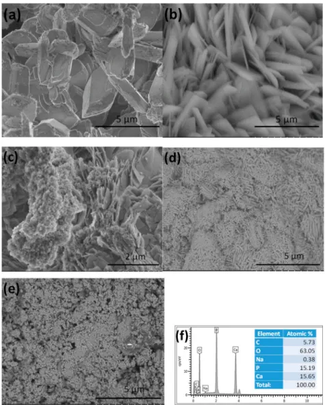
3.1. Morphological Characterization of CPC Coatings Prepared by ED with Different Deposition Parameters Figure2demonstrates the morphological characteristics of coatings deposited with different parameters. It is visible that the particles in the S1 sample had mainly large, thick, rectangular plate-like morphology with length of 4–6µm and width of 0.5–2 µm (Figure2a). The corresponding EDX measurement confirmed the Ca/P ratio as 1.03 (Figure2f), which is the elemental ratio in monetite (CaHPO4). Similar results have been found in many research works [36–40]. In Figure2b, a remarkably thinner and relatively well-oriented, uniform platelets are visible. The average size of the platelets was 3–4µm in length and 0.1–0.3µm in width. The higher current density resulted in smaller and thinner platelets. In the case of the S3 sample (Figure2c), the shapes of the deposited particles were mainly a mixture of non-uniform small needle-like particles at a nanometer size and larger thin, laminated plate-like particles at a micrometer size. In addition, flake-like aggregates were also formed. The Ca/P ratio in the CPC layer varied from 1.01 to 1.73 depending on the investigated site on the surface, which confirmed the different calcium phosphate phases present in the layer. It was visible that the morphology of the CPC layers significantly changed when the ratio ofton/toffdecreased.
The calcium phosphate crystals were larger when largertonwas applied (higher duty cycle).
According to Suchanek et al. [36], in an acidic calcium-phosphate solution (pH=4.0), the obtained crystals had a plate-like morphology with a smooth surface. The average width of particles was 4µm, while their length was 7µm. The particles formed large, irregular flakes with an average width of 2µm and length of 9µm at pH=6.0, while at pH=7.5, the size of the flakes decreased slightly to around 1µm in width and 5µm in length. At pH values of 9.0 and 10.0, bundles of rods also appeared with a similar morphology of crystals. While at pH=11.0, the shape of the crystals were mainly nanofibers with a width of 100 nm and length of 1.5µm. Among the calcium phosphate phases, monetite is the most stable phase under acidic conditions below pH 2.7 [37]. Macha et al. [40] reported monetite with a rectangular block morphology that could transform to hydroxyapatite (HAp) with a morphology of mesh-like thin platelets. It is highly dependent on pH condition, and forms a CaP phase, preferably monetite or HAp. As pH increased, monetite became unstable and converted to HAp [41,42].
Monasterio et al. [43] have also proven that the as-deposited CPCs had plate-like morphology at all examined current densities and the size of plates decreased by increasing the current density.
HAp coating with a flower-like structure was also successfully developed by pulsed electrochemical deposition (PED) with average current density of 1 mA/cm2. Evenly sized flower-like apatite crystals could be deposited onto a titanium substrate when a longer pulse offtime was applied [44]. In the work of Seyedraoufi et al. [34], the increasing duty cycle led to changes in crystal structure of the coatings and smaller particles were deposited at higher duty cycles. However, this finding does not correlate with our experiments, when the higher duty cycle (50%) resulted in larger CPC blocks while at a lower duty cycle (9%), we obtained smaller, thin plate-like particles. Chakraborty et al. [45] reported that electrodeposition with higher current density elevated the rate of phase transformation between calcium hydrogen phosphate and hydroxyapatite compared to deposition with lower current density and thus increased the Ca/P ratio accordingly. Low current density (5 mA/cm2) produced surface with nano-roughness (400 to 500 nm), which is the best condition for bone tissue growth. However,
deposition with high current density might cause crack formation. By increasing the current density, the coating was found to be more porous with a lower crystallite size (nano-range) and the amount of hydroxyapatite phase in the coating increased.
Figure 2.SEM images on CPC coatings prepared by different parameters. (a)ton: 5 ms,toff: 5 ms,ip: 0.4 A·cm−2, S1 sample. (b)ton: 5 ms,toff: 5 ms,ip: 1 A·cm−2, S2 sample. (c)ton: 1 ms,toff: 10 ms,ip: 5 A·cm−2, S3 sample. (d) S4: S3 sample after treatment in 1 M NaOH solution, (e) S5: S3 sample after heat treatment at 900◦C and (f) the corresponding EDX spectra and elemental composition of S1.
The pulse current can enhance the crystallinity of CaP films deposited on a metallic substrate compared to layers deposited by the direct current method. Furthermore, thetofftime of the cycle in the pulsed electrodeposition method gives Ca2+and PO43−ions in the bulk solution sufficient time to diffuse to the vicinity of the cathode thus maintaining favorable conditions for HAp deposition.
The HAp coating prepared by the pulsed method was more compact and uniform when the deposition was performed with low current density of 0.5 mA/cm2with longertoff time. Increasing the peak current density or decreasing pulse off time led to a less uniform, flake-like microstructure and rougher, porous coatings [46]. Moreover, the coatings deposited by the pulsed current also had better adhesion and they were more uniform than those made by the DC current [47]. Figure2d revealed the morphology of the S3 sample after treatment in an alkali solution for 2 h (S4). It can be seen that the layer consisted of small needle- or thorn-like, disoriented particles in the size of about 100–300 nm
in length and 10–50 nm in width. A high pH value above 11 favors the phase transformation from monetite to hydroxyapatite [48–53]. The Ca/P elemental ratio in this case was 1.78, which can indicate that mainly hydroxyapatite crystals are present in the coating. It can be seen in Figure2e, that the heat treatment at 900◦C also caused considerable change in the morphology of the S3 sample (S5). In this case, the layer consists of small, needle-like particles and agglomerated flakes in nanometer size, with an average Ca/P ratio of 1.69. This can also imply the layer to be mainly hydroxyapatite with a small amount of other CaP phases such as tricalcium phosphate (TCP) as contamination.
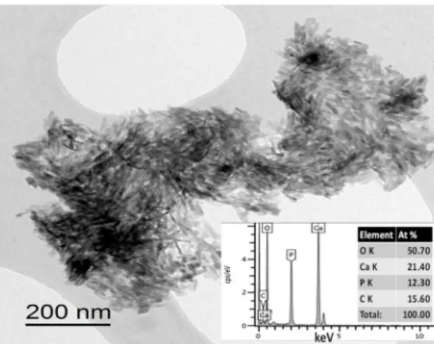
Figure3shows the TEM image of the S4 sample. This also confirmed the small needle-like character of the coating particles. This shape is characteristic of hydroxyapatite crystals [54]. In the corresponding EDX analysis, the Ca/P elemental ratio was 1.73.
Figure 3.TEM image and EDX elemental analysis of the S4 sample.
3.2. Structural Analysis of CPC Coatings
3.2.1. FTIR Measurements
As Figure4demonstrates, the FTIR spectra were very similar for all coatings. In the spectra, peaks at around 627, 960, 990, and 1130 cm−1were connected to the PO43−anionic group. The broad absorption peak in the 1400–1500 cm−1region can be attributed to the absorbed CO32−
content of the calcium phosphate phases [55]. Weaker overlapped peaks at 875 cm−1can be related to HPO42−
content. The vibrations at around 1390 and 863 cm−1suggest the presence of carbonate anions in coatings. The former peak is the asymmetric stretching of the C–O group while the latter can be attributed to the out-of-plane bending vibration of the C–O group [56]. The absorption peak of the OH−groups (OH−stretch vibration) was present at 3700 cm−1. In addition, slight peaks related to adsorbed water also appeared on the spectra from 3600 cm−1to around 2600 cm−1and at 3570 cm−1. 3.2.2. X-Ray Diffraction XRD Measurements
XRD patterns of the CPC coatings are shown in Figure5. The straight baseline and sharp peaks on the diffractograms of the S1, S2, S3, and S5 samples indicate that the layers are partially crystallized.
However, the diffractogram of sample S4 showed significantly broadened characteristic peaks with lower intensity that can be attributed to its mainly amorphous characteristics with smaller, nano-sized particles or its nano-crystallinity.
Figure 4.FTIR measurements on CPC layers prepared by the pulse current with different parameters.
Figure 5.XRD patterns of CPC layers prepared by the pulse current with different parameters.
The phase of samples S1, S2, and S3 was mainly monetite or dicalcium phosphate (CaHPO4, DCP, JCPDS89-5969), however, a small amount ofα-Tricalcium phosphate phase (Ca3(PO4)2, TCP, JCPDS file number 09-0348) could also be identified. It is visible that the relative intensity and width of the characteristic peaks varied in the S1–S3 samples, depending on the preparation parameters, which also indicates different phase ratios. On the other hand, samples S4 and S5 only exhibited the characteristic peaks of hydroxyapatite (HAp, JCPDS76-0694). The main characteristic diffraction peaks were found at 2θ=31.770◦, 32.190◦, and 32.905◦and indexed as (211), (112), (300) planes, respectively, which corresponded to Bragg’s reflection of HAp. The surface treatment in alkaline solution and the heat treatment caused phase transformation from monetite/TCP to pure hydroxyapatite.
The heat treated CPC (S5) exhibited well crystallized sharp peaks of HAp. The better crystallization of sample S5 was proven by narrower and sharper peaks (thinner Bragg peaks) compared to the wider and smaller peaks of S4, which is probably due to the poor crystallinity of the material [57].
3.2.3. Electrochemical Evaluation of the Coatings
The long-term corrosion properties of the substrate material and CPC coating (S5 sample) were compared in our experiments. As Figure6shows, the shapes of the potentiodynamic curves recorded after different immersion times were similar. In all cases, large anodic passive regions were visible on the anodic branch of the potentiodynamic curves and the measured passive current densities (jp) were
small. The range of the passive region was from around+350 mV vs. Ag/AgCl to+900 mV–+1.15 V vs.
Ag/AgCl (passive film breakdown potential).
Figure 6. Potentiodynamic polarization curves of the uncoated Ti6Al4V alloy (a) and CPC coating (S5) (b) in Ringer’s solution as well as Ti6Al4V alloy (c) and CPC coating (d) in SBF solution recorded several times over a two-week immersion period at 37◦C. The potential scanning rate was 1 mV s−1in each case.
In Ringer’s solution, the passive current values for the implant material decreased more significantly over time from 50 to 20 nAcm−2, compared to thejpvalues of the CPC coating, where the passive currents hardly changed over immersion time. In this case, there were two distinctive plateaus in the anodic region, one with ajpof 21.3 nAcm−2from the 80 to 290 mV electrode potential range and the other with ajpof 30.6 nAcm−2from the 80 to 290 mV electrode potential range. The layer breakdown and re-passivation occurred at the 425 mV electrode potential. The curves recorded in SBF solution showed similar forms with a large anodic passive region. However, in this case, the passive current densities were higher by almost two orders of magnitude, and decreased from 1.96 to 1µAcm−2and from 4.67 to 1.1µAcm−2for the substrate implant and CPC coating, respectively.
In addition, the shifting ofEcorrvalues to more negative potentials over time was more apparent.
This may indicate that the possibility of dissolution processes taking place at the electrode surface is higher in the SBF electrolyte and for the CPC coating due to the higher ionic activity and slightly lower pH of the electrolyte.
A similar tendency was observed for the corrosion current (jcorr) values. Thejcorrvalues were higher by more than one order of magnitude for both the implant material and the CPC coating in SBF solution than in Ringer’s solution (Figure7b). Thejcorrvalues showed a slight decreasing tendency with time, while for the implant, they reached a quasi-steady state. This also proves the surface passivation of the uncoated implant and the gradual and slow precipitation/dissolution of corrosion products in the case of the coated sample during immersion. The lowest corrosion currents were measured on the uncoated implant, indicating its highest corrosion resistance.
Figure 7.Potentiodynamic polarization curves after two weeks of immersion (a) and the measured corrosion current densities over time (b) of the CPC coating (S5) and substrate material in different physiological solutions.
The corrosion potentials demonstrated more negative values in SBF solution than in Ringer’s solution, which are also proof of its higher activity. Moreover, theEcorrof the CPC coating was more negative than that of the uncoated implant.
3.2.4. Contact Angle Measurements on CPC Coatings
The hydrophilic characteristic of CPCs is highly important since surface energy has a key role in osteogenesis. The surface of the hydrophilic implant is positively charged and has high surface energy, thus proteins that are essential for cell interaction can easily adhere to the surface [58].
The wettability of CPCs can be altered by an innovative post-treatment of exposing the surface to low energy electron irradiation [59]. The surface energy of the implant can also affect the bone cell proliferation and differentiation as well as the osteointegration [60,61]. The cellular reaction can be different for hydrophilic and hydrophobic implants, especially in the early stage of wound healing.
Surfaces with higher surface energy possess more rapid cell activity and differentiation than those with lower surface energy [62]. The bone cells can more easily adhere to and proliferate on hydrophilic substrates [63].
As Figure8demonstrates, the implant material (TiAl6V4) had a contact angle of 23.2◦. Applying CPC coatings on the surface improved their wettability and hydrophilicity. The contact angle measured on the CPC coating (S5) decreased by around 45%. This result is in good correlation with the research works of Nerantzaki et al. [33] and Fan et al. [64].
Figure 8.Contact angle measurements (a) on titanium alloy substrate; (b) on CPC coating (S5).
3.2.5. Cell Viability Measurements
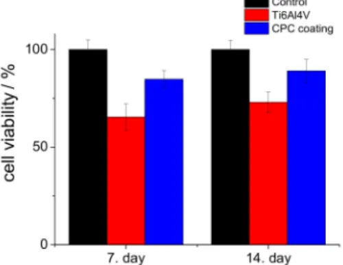
Figure9shows the viability percentages of cells seeded on the substrate material and CPC coating (S5) compared to the control samples. We investigated the biocompatibility properties of sample S5 because this coating was pure hydroxyapatite, which is the main component of human bone. It was clear that in all culture periods, the CPC coating possessed the highest cell viability values; after seven days, it was above 84%, while after two weeks, it had increased to around 89% compared to
the positive control. These measurements proved that the CPC coating, especially the hydroxyapatite phase, promotes the attachment and growth of osteoblastic cells due to its high hydrophilic property and advantageous morphology [65,66].
Figure 9.Cell viability values (in percentage) of the substrate material and CPC sample (S5) compared to the positive control. MG-63 cells were grown in well plates without samples as the positive control.
4. Conclusions
The effects of pulse current deposition parameters on the morphology, structure, and thus the biocompatibility properties of CPC coatings were investigated. The experiments demonstrated that the CPC coatings after electrodeposition consisted of mainly large, plate-like grains in the monetite phase. The size, thickness, and orientation of these platelets were largely dependent on the applied parameters such as the length oftonand the current density. The decrease in theton/toffratio resulted in thinner, more oriented platelets, while the increase in current density caused a significant decrease in grain size. After applying an alkali treatment (at pH value above 11), the layer consisted of small needle or thorn-like disoriented particles in the size range of about 100–300 nm in length and 10–50 nm in width. The higher pH value favored the phase transformation from monetite to hydroxyapatite.
The heat treatment at 900◦C for 30 min also resulted in phase transformation to the hydroxyapatite phase with higher crystallinity than in the case of alkali treatment. This fact was also proven by XRD measurements, where the better crystallization of the heat treated sample was demonstrated by thinner and larger Bragg peaks compared to the wider and smaller peaks of the alkali-treated sample.
The corrosion measurements confirmed that the CPC coating had slightly lower corrosion resistance, which can be attributed to the dissolution/precipitation processes of calcium phosphates, while the surface of the implant material was covered with a compact and stable oxide layer. The contact angle measurements showed increased hydrophilicity, and accordingly, the cell viability measurements clearly showed better biocompatibility for the CPC coating than for the uncoated implant material.
Author Contributions: Conceptualization, M.F. and C.B.; validation, C.B.; investigation, M.F.; resources, M.F.
and C.B.; data curation, M.F.; writing—original draft preparation, M.F.; writing—review and editing, M.F. and C.B.; supervision, C.B.; project administration, M.F.; funding acquisition, M.F. and C.B. All authors have read and agreed to the published version of the manuscript.
Funding:This research was funded by the QualityNano project (EU-Seventh Framework Program, grant number:
UNIVLEEDS-TAF-455), JECS TRUST (2015100), COST Action-TD1204 MODENA, and OTKA-PD 131934.
Acknowledgments:The authors are grateful to J. Harrington, M. Ward, Y. Jiang, T.A. Wilkins (University of Leeds, UK), and L. Illes (MTA-EK, Hungary) for the SEM/EDX measurements. We thank V. Havasi and Z. Kónya (University of Szeged, Hungary) for the FTIR measurements, and Zs. Horváth (MTA-EK, Hungary) for the XRD measurements.
The biocompatibility measurements were performed at Rizzoli Orthopedic Institute, Bologna, thanks to E. D.
Bella and M. Fini, and A. Grünewald, R. Detsch, and A.R. Boccaccini at the Friedrich-Alexander-University Erlangen-Nuremberg, Department for Materials Science.
Conflicts of Interest:The authors declare no conflict of interest.
References
1. Jacobs, J.J.; Hallab, N.J.; Urban, R.M.; Wimmer, M.A. Wear particles.J. Bone Jt. Surg. Am.2006,88(Suppl. 2), S99–S102.
2. Williams, D.F. On the mechanisms of biocompatibility.Biomaterials2008,29, 2941–2953. [CrossRef]
3. Tengvall, P.; Lunstrom, I. Physico-chemical considerations of titanium as a biomaterial.Clin. Mater.1992,9, 115–134. [CrossRef]
4. Ratner, B.D.; Bryant, S.J. Biomaterials: Where we have been and where we are going.Annu. Rev. Biomed.
Eng.2004,6, 41–75. [CrossRef]
5. Anderson, J.M. Biological responses to materials.Annu. Rev. Mater. Sci.2001,31, 81–110. [CrossRef]
6. Goto, T.; Narushima, T.; Ueda, K. Bioceramic coating on titanium by physical and chemical vapor deposition.
InBiological and Biomedical Coatings Handbook, 1st ed.; Zhang, S., Ed.; Taylor & Francis Group: Milton Park Abingdon, UK, 2011; Chapter 7; pp. 299–332.
7. Espallargas, N.; Torres, C.; Muñoz, A.I. A metal ion release study of CoCrMo exposed to corrosion and tribocorrosion conditions in simulated body fluids.Wear2015,332–333, 669–678. [CrossRef]
8. Atapour, M.; Wang, X.; Färnlund, K.; Wallinder, I.O.; Hedberg, Y. Corrosion and metal release investigations of selective laser melted 316L stainless steel in a synthetic physiological fluid containing proteins and in diluted hydrochloric acid.Electrochim. Acta2020,354, 136748. [CrossRef]
9. Sansone, V.; Pagani, D.; Melato, M. The effects on bone cells of metal ions released from orthopaedic implants.
A review.Clin. Cases Miner. Bone Metab.2013,10, 34–40. [CrossRef]
10. Hallab, N.J.; Vermes, C.; Messina, C.; Roebuck, K.A.; Glant, T.T.; Jacobs, J.J. Concentration-and composition-dependent effects of metal ions on human MG-63 osteoblasts.J. Biomed. Mater. Res.2002,60, 420–433. [CrossRef]
11. Nakonieczny, D.; Walke, W.; Majewska, J.; Paszenda, Z. Characterization of magnesia-doped yttria-stabilized zirconia powders for dental technology applications.Acta Bioeng. Biomech.2014,16, 99–106.
12. Nakonieczny, D.; Paszenda, Z.K.; Basiaga, M.; Radko, T.; Drewniak, S.; Podwórny, J.; Bogacz, W. Phase composition and morphology characteristics of ceria-stabilized zirconia powders obtained via sol–gel method with various pH conditions.Acta Bioeng. Biomech.2017,19, 21–30.
13. Salamanka, E.; Pan, Y.-H.; Tsai, A.I.; Lin, P.-Y.; Lin, C.-K.; Huang, H.-M.; Teng, N.-C.; Wang, P.D.;
Chang, W.-J. Enhancement of osteoblastic-like cell activity by glow discharge plasma surface modified hydroxyapatite/β-tricalcium phosphate bone substitute.Materials (Basel)2017,10, 1347. [CrossRef]
14. Takahashi, H.; Yashima, M.; Kakihana, M.; Yoshimura, M. Synthesis of stochiometric hydroxyapatite by a gel route from the aqueous solution of citric and phosphone acetic acids.Eur. J. Solid State Inorg. Chem.1995,32, 829–835.
15. Gligorijevic, B.R.; Vilotijevic, M.; Scepanovic, M.; Vidovic, D.; Radovi, N.A. Surface structural heterogeneity of high power plasma-sprayed hydroxyapatite coatings.J. Alloy. Compd.2016,687, 421–430. [CrossRef]
16. Tsui, Y.C.; Doyle, C.; Clyne, T.W. Plasma sprayed hydroxyapatite coatings on titanium substrates Part 1:
Mechanical properties and residual stress levels.Biomaterials1998,19, 2015–2029. [CrossRef]
17. Su, Y.; Li, K.; Tielens, F.; Wang, J. Effect of sprayed techniques on the surface microstructure and in vitro behavior of nano-HAp coatings.Mater. Sci. Eng. C2020,117, 111318. [CrossRef]
18. Choy, K.L. Chemical vapour deposition of coatings.Prog. Mater. Sci.2003,48, 57–170. [CrossRef]
19. Hontsu, S.; Hashimoto, Y.; Yoshikawa, Y.; Kusunoki, M.; Nishikawa, H.; Ametani, A. Fabrication of hydroxyl apatite coating titanium web scaffold using pulsed laser deposition method. J. Hard Tissue Biol.2012,21, 181–188. [CrossRef]
20. Eliaz, N.; Ritman-Hertz, O.; Aronov, D.; Weinberg, E.; Shenhar, Y.; Rosenman, G.; Weinreb, M.; Ron, E.
The effect of surface treatments on the adhesion of electrochemically deposited hydroxyapatite coating to titanium and on its interaction with cells and bacteria. J. Mater. Sci. Mater. Med. 2011,22, 1741–1752.
[CrossRef]
21. Thanh, D.T.; Nam, P.T.; Phuong, N.T.; Que, L.X.; Van Anh, N.; Hoang, T.; Lam, T.D. Controlling the electrodeposition, morphology and structure of hydroxyapatite coating on 316L stainless steel.Mater. Sci.
Eng. C2013,33, 2037–2045. [CrossRef]
22. Furko, M.; Balázsi, K.; Balázsi, C. Comparative study on preparation and characterization of bioactive coatings for biomedical applications—A review on recent patents and literature.Rev. Adv. Mater. Sci.2017, 48, 25–51.
23. Bosco, R.; Van Den Beucken, J.; Leeuwenburgh, S.; Jansen, J. Surface engineering for bone implants: A trend from passive to active surfaces.Coatings2012,2, 95–119. [CrossRef]
24. Epinette, J.-A.; Manley, M.T.Fifteen Years of Clinical Experience with Hydroxyapatite Coatings in Joint Arthroplasty, 1st ed.; Geesink, R.G.T., Ed.; Springer: Paris, France, 2004; ISBN 978-2-287-00508-4. [CrossRef]
25. Li, H. Thermal sprayed bioceramic coatings: nanostructured hydroxyapatite (HA) and HA-based composites.
InBiological and Biomedical coatings Handbook, 1st ed.; Zhang, S., Ed.; Taylor & Francis Group: Milton Park Abingdon, UK, 2011; Chapter 4; pp. 137–202.
26. Williams, D.F. Definitions in Biomaterials: Proceedings of a Consensus Conference of the European Society for Biomaterials. InProgress in Biomedical Engineering; Elsevier Science Ltd: New York, NY, USA, 1987.
27. Orsini, G.; Piattelli, M.; Scarano, A.; Petrone, G.; Kenealy, J.; Piattelli, A.; Caputi, S. Randomized, controlled histologic and histomorphometric evaluation of implants with nanometer-scale calcium phosphate added to the dual acid-etched surface in the human posterior maxilla. J. Periodontol.2007,78, 209–218. [CrossRef]
[PubMed]
28. Paital, S.R.; Dahotre, N.B. Calcium phosphate coatings for bio-implant applications: Materials, performance factors, and methodologies.Mater. Sci. Eng. R2009,66, 1–70. [CrossRef]
29. Bose, S.; Fielding, G.; Tarafder, S.; Bandyopadhyay, A. Trace element doping in calcium phosphate ceramics to understand osteogenesis and angiogenesis.Trends Biotechnol.2013,31, 594–605. [CrossRef]
30. Gopi, D.; Karthika, A.; Nithiya, S.; Kavitha, L. In vitro biological performance of minerals substituted hydroxyapatite coating by pulsed electrodeposition method.Mater. Chem. Phys.2014,144, 75–85. [CrossRef]
31. Kheradmandfard, M.; Fathi, M.H.; Ansari, F.; Ahmadi, T. Effect of Mg content on the bioactivity and biocompatibility of Mg-substituted fluorapatite nanopowders fabricated via mechanical activation.Mater.
Sci. Eng. C2016,68, 136–142. [CrossRef]
32. Uskokovic, V.; Uskokovic, D.P. Nanosized hydroxyapatite and other calcium phosphates: Chemistry of formation and application as drug and gene delivery agents.J. Biomed. Mater. Res. B Appl. Biomater.2011,96, 152–191. [CrossRef]
33. Nerantzaki, M.; Filippousi, M.; Van Tendeloo, G.; Terzopoulou, Z.; Bikiaris, D.; Goudouri, O.M.; Detsch, R.;
Grüenewald, A.; Boccaccini, A.R. Novel poly(butylene succinate) nanocomposites containing strontium hydroxyapatite nanorods with enhanced osteoconductivity for tissue engineering applications. Express Polym. Lett.2015,9, 773–789. [CrossRef]
34. Seyedraoufi, Z.S.; Mirdamadi, S. Effects of pulse electrodeposition parameters and alkali treatment on the properties of nano hydroxyapatite coating on porous Mg–Zn scaffold for bone tissue engineering application.
Mater. Chem. Phys.2014,148, 519–527. [CrossRef]
35. Pana, J.; Prabakaranb, S.; Rajan, M. In-vivo assessment of minerals substituted hydroxyapatite/poly sorbitol sebacate glutamate (PSSG) composite coating on titanium metal implant for orthopedic implantation.Biomed.
Pharmacother.2019,119, 109404. [CrossRef] [PubMed]
36. Suchanek, K.; Bartkowiak, A.; Perzanowski, M.; Marszałek, M. From monetite plate to hydroxyapatite nanofibers by monoethanolamine assisted hydrothermal approach. Sci. Rep. 2018,8, 15408. [CrossRef]
[PubMed]
37. Jokic, B.; Mitric, M.; Radmilovic, V.; Petrovic, S.D.R.; Janackovic, D. Synthesis and characterization of monetite and hydroxyapatite whiskers obtained by a hydrothermal method.Ceram. Int.2011,37, 167–173. [CrossRef]
38. Duncan, J.; MacDonald, J.F.; Hanna, J.V.; Shirosaki, Y.; Hayakawa, S.; Osaka, A.; Skakle, J.M.S.; Gibson, I.R.
The role of the chemical composition of monetite on the synthesis and properties ofα-tricalcium phosphate.
Mater. Sci. Eng. C2014,34, 123–129. [CrossRef]
39. Cama, G.; Nkhwa, S.; Gharibi, B.; Lagazzo, A.; Cabella, R.; Carbone, C.; Dubruel, P.; Haugen, H.; Di Silvio, L.; Deb, S. The role of new zinc incorporated monetite cements on osteogenic differentiation of human mesenchymal stem cells.Mater. Sci. Eng. C2017,78, 485–494. [CrossRef]
40. Macha, I.J.; Charvillat, C.; Cazalbou, S.; Grossin, D.; Boonyang, U.; Ben-Nissan, B. Comparative study of coral conversion, Part 3: Intermediate products in the first half an hour.J. Aust. Ceram. Soc.2016,52, 177–182.
41. Ben-Nissan, B.C.; Charvillat, C.; Oktar, F.N.; Grossin, D. Comparative study of coral conversion, part 2:
Microstructural evolution of calcium phosphate.J. Aust. Ceram. Soc.2015,51, 149–159.
42. Cegla, R.-N.R.; Macha, I.J.; Ben-Nissan, B.; Grossin, D.; Heness, G.; Chung, R.-J. Comparative study of conversion of coral with ammonium dihydrogen phosphate and orthophosphoric acid to produce calcium phosphates.J. Aust. Ceram. Soc.2014,50, 154–161.
43. Monasterio, N.; Ledesma, J.L.; Aranguiz, I.; Garcia-Romero, A.; Zuza, E. Analysis of electrodeposition processes to obtain calcium phosphate layer on AZ31 alloy.Surf. Coat. Technol.2017,319, 12–22. [CrossRef]
44. Gopi, D.; Karthika, A.; Sekar, M.; Kavitha, L.; Pramod, R.; Dwivedi, J. Development of lotus-like hydroxyapatite coating on HELCDEB treated titanium by pulsed electrodeposition.Mater. Lett.2013,105, 216–219. [CrossRef]
45. Chakraborty, R.; Sengupta, S.; Saha, P.; Das, K.; Das, S. Synthesis of calcium hydrogen phosphate and hydroxyapatite coating on SS316 substrate through pulsed electrodeposition.Mater. Sci. Eng. C2016,69, 875–883. [CrossRef] [PubMed]
46. Gopi, D.; Indira, J.; Kavitha, L. A comparative study on the direct and pulsed current electrodeposition of hydroxyapatite coatings on surgical grade stainless steel.Surf. Coat. Techn.2012,206, 2859–2869. [CrossRef]
47. Marashi-Najafi, F.; Khalil-Allafi, J.; Etminanfar, M.R. Biocompatibility of hydroxyapatite coatings deposited by pulse electrodeposition technique on the Nitinol superelastic alloy.Mater. Sci. Eng. C2017,76, 278–286.
[CrossRef] [PubMed]
48. Zou, Z.; Liu, X.; Chen, L.; Lin, K.; Chang, J. Dental enamel-like hydroxyapatite transformed directly from monetite.J. Mater. Chem.2012,22, 22637–22641. [CrossRef]
49. Shih, W.J.; Chen, Y.H.; Wang, S.H.; Li, W.L.; Hon, M.-H.; Wang, M.-C. Effect of NaOH(aq)treatment on the phase transformation and morphology of calcium phosphate deposited by an electrolytic method.Cryst.
Growth2005,285, 633–641. [CrossRef]
50. Chen, H.-T.; Wang, M.-C.; Chang, K.-M.; Wang, S.-H.; Shih, W.J.; Li, W.-L. Phase transformation and morphology of calcium phosphate prepared by electrochemical deposition process through alkali treatment and calcination.Metall. Mater. Trans A2014,45, 2260–2269. [CrossRef]
51. Shih, W.J.; Wang, M.C.; Chang, K.M.; Wang, C.L.; Wang, S.H.; Li, W.L.; Huang, H.H. Phase transformation of calcium phosphates by electrodeposition and heat treatment.Metall. Mater. Trans. A2010,41, 3509–3516.
[CrossRef]
52. Huang, C.; Cao, P. Tuning Ca:P ratio by NaOH from monocalcium phosphate monohydrate (MCPM).Mater.
Chem. Phys2016,181, 159–166. [CrossRef]
53. Prado Da Silva, M.H.; Lima, J.C.H.; Soares, G.A.; Elias, C.N.; de Andrade, M.C.; Best, S.M.; Gibson, I.R.
Transformation of monetite to hydroxyapatite in bioactive coatings on titanium.Surf. Coat. Technol.2001, 137, 270–276. [CrossRef]
54. Koutsopoulos, S. Synthesis and characterization of hydroxyapatite crystals: A review study on the analytical methods.J. Biomed. Mater. Res.2002,62, 600–612. [CrossRef]
55. Berzina-Cimdina, L.; Borodajenco, N. Research of calciumphosphates using Fourier transform infrared spectroscopy. InInfrared Spectroscopy—Materials Science Engineering and Technology; Theophile, T., Ed.;
IntechOpen Ltd: London, UK, 2012; pp. 123–148. ISBN 978-953-51-0537-4.
56. Roveri, N.; Falini, G.; Sidoti, M.C.; Tampieri, A.; Landi, E.; Sandri, M.; Parma, B. biologically inspired growth of hydroxyapatite nanocrystals inside self-assembled collagen fibers.Mater. Sci. Eng. C2003,23, 441–446.
[CrossRef]
57. Singh, A. Hydroxyapatite, a biomaterial: Its chemical synthesis, characterization and study of biocompatibility prepared from shell of garden snail, Helix aspersa.Bull. Mater. Sci.2012,35, 1031–1038. [CrossRef]
58. Jimbo, R.; Ivarsson, M.; Koskela, A.; Sul, Y.T.; Johansson, C.B. Protein adsorption to surface chemistry and crystal structure modification of titanium surfaces.J. Oral Maxillofac. Res.2010,1, e3. [CrossRef] [PubMed]
59. Aronov, D.; Rosen, R.; Ron, E.Z.; Rosenman, G. Tunable hydroxyapatite wettability: Effect on adhesion of biological molecules.Proc. Biochem.2006,41, 2367–2372. [CrossRef]
60. Zhao, G.; Schwartz, Z.; Wieland, M.; Rupp, F.; Geis-Gerstorfer, J.; Cochran, D.L.; Boyan, B.D. High surface energy enhances cell response to titanium substrate microstructure.J. Biomed. Mater. Res. A2005,74, 49–58.
[CrossRef]
61. Kilpadi, D.V.; Lemons, L.E. Surface energy characterization of unalloyed titanium implants.J. Biomed. Mater.
Res.1994,28, 1419–1425. [CrossRef]
62. Eriksson, C.; Nygren, H.; Ohlson, K. Implantation of hydrophilic and hydrophobic titanium discs in rat tibia: Cellular reactions on the surfaces during the first 3 weeks in bone.Biomaterials2004,25, 4759–4766.
[CrossRef]
63. Anselme, K. Osteoblast adhesion on biomaterials.Biomaterials2000,21, 667–681. [CrossRef]
64. Fan, R.R.; Zhou, L.X.; Song, W.; Li, D.X.; Zhang, D.M.; Ye, R.; Zheng, Y.; Guo, G. Preparation and properties of g-TTCP/PBS nanocomposites and its in vitro bio-compatibility assay.Int. J. Biol. Macromol.2013,59, 227–234.
[CrossRef]
65. Kilpadi, K.L.; Chang, P.L.; Bellis, S.L. Hydroxylapatite binds more serum proteins, purified integrins, and osteoblast precursor cells than titanium or steel.J. Biomed. Mater. Res.2001,57, 258–267. [CrossRef]
66. Thian, E.S.; Ahmad, Z.; Huang, J.; Edirisinghe, M.J.; Jayasinghe, S.N.; Ireland, D.C.; Brooks, R.A.; Rushton, N.;
Bonfield, W.; Best, S.M. The role of surface wettability and surface charge of electrosprayed nanoapatites on the behaviour of osteoblasts.Acta Biomater.2010,6, 750–755. [CrossRef] [PubMed]
©2020 by the authors. Licensee MDPI, Basel, Switzerland. This article is an open access article distributed under the terms and conditions of the Creative Commons Attribution (CC BY) license (http://creativecommons.org/licenses/by/4.0/).


![degradationofcoatingsisfavourablefrombothclinicalandbiomedicalpointsofview. ofbiomedicalapplications[ , ].Themainapproachisthatthebioceramiccoatingsact toincreasethebiocompatiblecharacteristicsofimplants.Thiscanbebestachievedby theimplants.Generally,thema](data:image/gif;base64,R0lGODlhAQABAIAAAP///wAAACH5BAEAAAAALAAAAAABAAEAAAICRAEAOw==)