S Z E K F O G L A L O ELO A D A SO K A M AGYAR TU D O M A N Y O S A K A D E M IA N
Hendrik Van Brussel
A SYSTEMS APPROACH
TO M ANUFACTURING SCIENCE
---
y z y .' /
s,
/ o f - * J 7U , . - ^ jJ ‘ j/ ‘“ ' '" / / M r * I "
/ A , l u , 1 ^
A ^ ^ j# * * 1
7 / / ^ - / / - * * ; A ^ ' ^ ■ ^ ^ '7 ^ 7 ^ * / ^ ^ / V > * y ^ ^
r ' a ^ a " , / , « - .
. . A i ^ ^ ---- T^/J
> //rt LUy
e/ < j * ^ 4' ' ...
• ■ " " y " ' v A *
/ ' . / ,,het <^V ✓ /
' , < ' , ’ -c a
y x ,
t i i i a / J J J ^ 9•f " 7 , : t ^ 1 ' , ..., * , > " " ■
/,//
/# # ■ u / u * “/ / „ . » / ' 7 ', . ,,„'/-"
■ h “ / ‘ “ ' " ‘
// .»•
* * ' , / a / ■ ' '^ I I / “
/- iV t V -* '
1 ! > <- <J
/ / > -
' / a J 7 ' * *
t-y u r
7 0, L ^ ‘ f t ^ / / : !j £ ~ A Z ^ h
H en d rik Van Brussel
A S Y S T E M S A PPRO A CH T O M A N U F A C T U R IN G S C IE N C E
SZEKFOGLALOK
A MAGYAR TUDOMANYOS AKADEMIAN INAUGURAL LECTURES
AT THE HUNGARIAN ACADEMY OF SCIENCES
A 2013. majus 6-an megvalasztott akademikusok szekfoglaloi Inaugural lectures by new members
elected on 6 May, 2013
Hendrik Van Brussel
A SYSTEMS APPROACH TO MANUFACTURING SCIENCE
Magyar Tudomanyos Akademia • 2014
Az eloadas elhangzott 2013. oktober 10-en Delivered on 10 October, 2013.
Sorozatszerkeszto • Series editor: Bertok, Krisztina
Angol nyelvi lektor • English reader: Torkos, Bela
Borito es tipografia • Cover and typography: Auri Grafika
ISSN 1419-8959 ISBN 978-963-508-741-9
© Hendrik Van Brussel
Kiadja a M agyar Tudomanyos Akademia • Published by the Hungarian Academy o f Sciences Kiadasert felel • Person in charge o f publication: Lovasz, Laszlo, az M T A elnoke • President o f H A S
Felelos szerkeszto • Editor-in-chief: Kindert, Judit N yom dai munkalatok • Printed by: Kodex Konyvgyarto K ft.
ABSTRACT
Present and future manufacturing engineering research should be inspired by the ongoing industrial and societal paradigm shifts. It is important for re
searchers in manufacturing science to detect these changes at an early stage, and to develop methods and technologies to cope with them appropriately. The complexity of the arising problems is so vast that only an integrated systems approach -not the traditional Taylorian approach- is beneficial. In this inau
gural lecture, some of these paradigm shifts, and their underlying technology drivers, which have dominated the research and teaching career of the speaker, are identified and elaborated upon. The marked advantages of the integrated systems view are illustrated with representative cases in mechatronics, holonic manufacturing systems (HMS), robotics, precision engineering, and microsys
tems technology (M ST), taken from the long research experience of the au
thor and his colleagues at Division PM A (Production engineering, Machine design and Automation), K U Leuven, Belgium.
i. INTRODUCTION
Gradually, a consensus is growing among European industrial and political leaders that a strong European manufacturing industry is essential for E u rope’s survival as a world-leading region. While this was 35% in 1970, manu
facturing economy is still responsible for 20% of employment in Europe. In the E U member countries, the share of manufacturing in the added value is between 17 and 23 %. The importance of manufacturing as a creator o f indirect
IIK N D R IK V A N B RU SSE L: A S Y S T E M S A P P R O A C H T O M A N U F A C T U R I N G S C IE N C E 5
jobs has been proven. Every direct job in manufacturing creates between two and five indirect jobs.
The manufacturing industry stimulates, as no other industrial sector, re
search and development -in Germany the automotive industry is the most innovative industrial sector- as well as the demand for services. The manu
facturing sector provides a major share of the private (up to 90%), and public financing of research and development. It plays an essential role in the innova
tion process and the technological progress. The success of the integration of new technologies, such as microsystem technology (M ST), IC T , new materi
als, nanotechnology and biotechnology, in new products, in the first place depends on the availability of appropriate production methods. Only those locations that master all technological and organisational aspects of the emer
gence and the lifecycle of innovative products have a future in the industrial landscape of the 21st century. This is a strong plea for a vigorous local (rather than global) manufacturing industry that can build up strong ‘industrial com
mons’ (production infrastructure and processes) as a fertile soil for innovation.
In order to safeguard and strengthen the European manufacturing indus
try, the E U and several technologically advanced member countries have set up extensive research programmes. In order to be relevant, these programmes have to take into account the ongoing industrial and related societal paradigm shifts (PSs) as the base for these programmes, and the technology drivers (TDs) that enable to cope with these shifts.
2. INDUSTRIAL PARADIGM SHIFTS AND THE MANUFACTURING INDUSTRY
For the sake of this inaugural lecture, I have identified five industrial paradigm shifts (PSs) that have (had) a profound influence on the manufacturing indus
try. They are the following:
6 S Z E K F O G L A L O K A M A G Y A R T U D O M A N Y O S A K A D F .M IA N
PSi Drastic reduction o f time-to-market
In the automotive industry, time-to-market has been reduced from 60 months to less than 20 months over a period of fifteen years, and other industries have followed suit. This has only become possible by the introduction of new design and engineering approaches, as technology drivers, such as:
• T D 11 Concurrent engineering (C E) at all levels of the manufacturing cycle, to enhance design and manufacturing efficiency. This implies for instance that, where possible, product and production system are to be designed simultaneously, or otherwise, that the product be de
signed as a function of the existing production system.
• T D 12 The mechatronic design methodology (simultaneous design, inte
grated design) as the most important enabling technology of the con
current engineering paradigm. It implies that during the design all aspects (mechanical, control, software ...) should be simultaneously taken into account, making the design a multi-criterion optimisation exercise.
• T D 13 New machine concepts (e.g. parallel kinematic machines [PKM], modular and reconfigurable machines, hybrid machine tools) are re
quired to implement the new manufacturing methods (high-speed machining, E L ID grinding, dry cutting ...) needed to reduce time- to-market.
PS2 A broader vision o f ‘performance’ (of products and production systems)
T he performance of products and production systems (meta-products) is de
termined not only by productivity, but also by precision, size, sustainability, cost. Technology drivers to achieve this are the following:
H E N D R IK VA N B R U SSE L: A S Y S T E M S A P P R O A C H T O M A N U F A C T U R IN G S C IE N C E 7
• T D 21 Integrated. (ubiquitous) quality control and real-tbne condition ??ionitor- ing systems are indispensible to be able to control each step in the production cycle, at runtime. This requires the development of suitable (miniaturized) sensors, and appropriate signal processing techniques (feature detection, feature classification, failure mode identification).
• TD 22 Life cycle design. The design requirements are extended from func
tional design to design for X, where X stands for an array of requirements, such as: easy manufacture, assembly, use, disassembly, packaging, mainte
nance, minimal life cycle cost, ecological impact, etc.
• TD23 The mechatronic design methodology enhances quality and perfor
mance through better (robust, resilient) products and better manufactur
ing control.
• T D 24 Miniaturisation leads to more functionality in a smaller package, and to lighter and smaller products.
• TD 25 New materials lead to better, smaller, stronger products, but they require appropriate production processes.
PS3 Towards mass customisation and the service economy
Personalisation of products requires the flexible production of high-perfor
mance products in small batches, even one-of-a-kind, at mass production rates and cost. However, Products and production systems should be ‘tailor made’, not
‘Taylor made’. Indeed, optimality is not obtained by optimising each element separately, as Taylor in his time advocated, but by simultaneous engineering, as advocated by the mechatronics approach. This requires, as technology drivers:
• TD 31 Enhanced flexibility and adaptability, achieved by introducing modular, plug-and-play compatible, reconfigurable manufacturing systems and products
8 S Z E K F O G L A L O K A M A G Y A R T U D O M A N Y O S A K A D E M lA N
• TD 32 Holonic (multi-agent) control o f manufacturing systems (heterarchical vs. hierarchical control), allowing flexible and robust behaviour of manu
facturing systems PS4 Towards ‘co-creation’
Industry has evolved from design O F the customer (1960s)) over design W IT H the customer (1980s), towards design B Y the customer (1990s and be
yond). This evolution has become possible by the following technology drivers:
• T D 4 1 The emergence of new, ICT-based manufacturing technologies (e.g.
rapid prototyping, 3D-printing), allowing closer collaboration with the customer.
• T D 4 2 Advanced use of I C T (standardised, open interfaces) enabling virtual entreprises, and plug-and-play compatibility between entreprise modules.
PS5 Towards the ‘ubiquitous machine/computer’
Machines have left the factory floor and they are increasingly intruding into our daily lives, sometimes without us being fully aware (‘the disappearing ma
chine’). For machines to be accepted in human-centered (but also in industrial) environments (health care, medical robotics, home and service robots, ware
house robots, museum guides) there is need for:
• T D 51 New ways o f‘programming' machines: task level control, holonic (multi-agent) control, learning by demonstration, behaviour based control, biologically inspired manufacturing control (ant colonies).
• TD 52 Natural ways o f hutmn/machine communication: voice input, natural (writing) interfaces for surgical robots, shared wheelchair control.
H E N D R IK V A N B R U S S E l.: A S Y S T E M S A P P R O A C H T O M A N U F A C T U R I N G S C IE N C E 9
Success will be ensured, when European manufacturing industry suc
ceeds in optimally satisfying: (i) Market needs, in terms of performance, cost efficiency, time-to-market, and (ii) Society needs, in terms of sustainability of products and production processes.
To satisfy these requirements simultaneously, the ‘intelligence’ of products and meta-products (manufacturing systems) should be drastically increased.
Intelligent manufacturing systems should behave like intelligent humans or hu
man societies, equipped with features like: (i) Autonomy, including learning capacity, robustness against disturbances, reasoning capability, and if possible (self)-awareness, and (ii) Social behaviour, including cooperation, predictive power, and social acceptance.
A n integral view on manufacturing is the key requirement to be able to introduce intelligence. T his means: (i) An integrated design approach for prod
ucts and meta-products, and (ii) An integrated manufacturing chain (design, production, quality control, logistics, sustainability).
3. MANUFACTURING SYSTEMS ARE COMPLEX (ADAPTIVE) SYSTEMS [1]
Systems, or problems, can be simple, complicated or complex. T he distinction has to do with the number of components and their interactions. A car is complex relative to a bicycle, but very simple relative to a manufacturing plant or an economy. One could say that a bicycle, that contains a hundred components, is a simple system, and a car, with some ten thousand components, a complicated system. A manufacturing plant, with many more components, would also be a complicated system, but it is more, it is also a complex system. W hy?
The behaviour of simple and complicated systems is well predictable.
I f one follows the assembly rules for a bicycle or a car, the behaviour of the as-
IO S Z E K F O G L A L O K A M A G Y A R T U D O M A N Y O S A K A D E M lA N
sembled system is predictable by knowing the starting conditions, because the relations between the system components are well-defined and fixed. At some point of complexity, we are unable to observe some underlying pattern by ob
serving its constituent parts in isolation. In a complex system, the same start
ing conditions can produce different outcomes depending on interactions of the elements in the system. At that point we say that there is some ‘emergent behaviour’ or self-organisation and declare the system ‘complex’. For example, building a highway is complicated, but managing urban traffic congestion is complex. Likewise, building a state-of-the-art air traffic control center is a complicated challenge in executing a project, while directing air traffic is com
plex, involving real-time problem-solving. In the same way, a manufacturing system is a complex system.
W hile a complex system consists o f a large number of components (often called ‘agents’) that interact, the term ‘complex adaptive system’ (CAS) refers to a complex system in which the components (called ‘holons’ here) not only interact, but also adapt and/or learn. Self-similarity is also often required for a CAS. A mechatronic system has a self-similar (fractal) nature when looked at on a component, machine and machine-system level. Adaptivity gives a com
plex system robustness (resilience) against disturbances and autonomic behaviour (homeostasis).
Optimdity is another important feature when designing complicated or complex systems. F.W . Taylor, the father of scientific management, claimed that a complex system/organization was optimal when each of its components was optimized separately. This Taylorian view stands perpendicular to the present, generally accepted view that optimality can only be achieved if the complicated/complex system is considered in its entirety, and subject to opti
misation as a whole.
H E N D R IK V A N B RU SSE L: A S Y S T E M S A P P R O A C H T O M A N U F A C T U R IN G S C IE N C E I I
4. MECHATRONICS AS AN INTEGRATED DESIGN PARADIGM [2]
Over the last half a century, Japan has gradually conquered a dominating position on the consumer electronics, automotive and machine tool markets.
Through their harmony model, built-in in their society, the integral approach to product design, advocated by the mechatronics design paradigm, was only a logical step for Japan in the evolution of their industry. T h ey realised very soon the advantages of a concurrent engineering approach to designing prod
ucts and meta-products and they launched the mechatronic design methodol
ogy already in the early 1970s.
Mechatronics is a powerful tool to satisfy the requirements of shorter time-to-market, increased quality and performance, and mass customisation.
Mechatronics combines machine design, control engineering, electronics, physics, and informatics in a synergetic way and gives rise to superior products.
In essence, mechatronics is the science of motion control. An essential fea
ture in the behaviour of a machine (system) is, indeed, the occurrence of con
trolled and/or co-ordinated motions of one or more machine elements. Typical examples can be found in robots, machine tools, compact-disc players, cars, computer disc drives, wafer steppers, etc. T he generation and co-ordination of the required motions in those machines, such that the increasingly growing performance and accuracy requirements are satisfied, makes up the raison d’etre o f mechatronics.
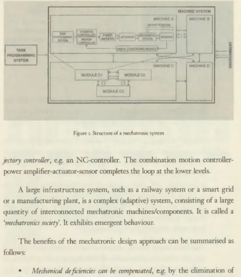
A complex mechatronic system consists of a hierarchy of levels: the ma
chine system level (factory), the machine level and the module or component level. It has a self-similar structure (Figure 1). Each level contains a task-programming module that materialises the man-machine or machine-machine interaction. The motion controller consists of a sequence controller, e.g. realised in a PLC , and a tra-
12 S Z E K F O G L A L O K A M A G Y A R T U D O M A N Y O S A K A D F .M IA N
Figure i. Structure o f a mechatronic system
jectory controller', e.g. an NC-controller. The combination motion controller- power amplifier-actuator-sensor completes the loop at the lower levels.
A large infrastructure system, such as a railway system or a smart grid or a manufacturing plant, is a complex (adaptive) system, consisting of a large quantity o f interconnected mechatronic machines/components. It is called a
‘mechatronics society'. It exhibits emergent behaviour.
The benefits of the mechatronic design approach can be summarised as follows:
• Mechanical deficiencies can be compensated, e.g. by the elimination of mechanical transmission elements and by compensating harmful me
chanical nonlinearities (e.g. friction, backlash) through appropriate modelling and feedforward, resulting in a better dynamic behaviour and a higher bandwidth. In Figure 2, it is shown that the position
ing behaviour of a spot welding robot is improved by applying the
H E N D R IK V A N B RU SSE L: A S Y S T E M S A PP R O A C H T O M A N U F A C T U R IN G S C IE N C E ! 3
End effector position (mm]
Time [s]
0.3
0
1-
End effector position [mm]
Time [s]
Figure i. Mechatronic design leads to better positioning behaviour
mechatronics design approach. The mechanical system is left un
changed, but the controller, by taking into account machine dynam
ics, leads to a markedly better performance.
• Machine elements can be made adaptable or ‘smart1 in the sense that their properties can be adapted to the circumstances. ‘Adaptronics’ is the term used in Germany to indicate this branch of mechatron
ics. For example, an active air bearing can adapt its stiffness and/
or damping to the needs imposed by the application (Figure 3 ) [3].
A change in air gap thickness is measured by a capacitive probe and fed back via a controller to piezoelectric actuators to counteract this change, resulting in an infinite static stiffness and a marked increase in dynamic stiffness up to high frequencies.
• High (positioning or tracking) accuracy of machine tools can be achieved through software compensation of disturbances such as friction in guideways or hysteresis in piezoelectric actuators, and/or by using alternative drive systems. A good example is the piezostepper, shown in Figure 4, which exhibits a positioning resolution of 2 nm and active stiffness control in 6 degrees of freedom [4].
■4 S Z E K F O G L A L O K A M A G Y A R T U D O M A N Y O S A K A D E M IA N
Shaft Air gap h0
Membrane Piezo actuator Capacitive sensor
Air supply
Op*n- and closed-loop stiftn*»s (h g-^m )
Figure 3. Adaptive air bearing
Figure 4. Piezostepper
Robust performance in the presence o f disturbances can be obtained by applying robust or adaptive (motion) controllers. As shown in Figure 5, the notorious quadrant glitch occurring at motion reversal in machine tools can be eliminated by feedforward of a pre-rolling friction model or by a disturbance observer [5].
H E N D R IK V A N B RU SSE L: A S Y S T E M S A P P R O A C H T O M A N U F A C T U R IN G S C IE N C E >5
no sia lic m o del G M S m o del d istu rb a n c e static m o d e l* G M S m odel +
c o m p e n sa tio n feedforw ard feedfonvard o b se rv e r o b s e r w r o b se rv er
-3 0 0 3 0 -3 0 0 3 0 -3 0 0 3 0 -3 0 0 3 0 -3 0 0 3 0 - 3 0 0 3 0
p o s itio n X [m m ) p o s itio n X [m m J p o sitio n X [ m m ] p o s itio n X [ m m | p o s itio n X [m m ] p o s itio n X [m m )
a n g le [ d e g r e e ) a n g le [ d e g r e e ] a n g le [ d e g r e e ] a n g l e [ d e g r e e ] a n g le [ d e g r e e ] a n g le [ d e g r e e ]
Figure 5. Accurate contouring through friction compensation and disturbance observer
5. TOWARDS THE ‘MECHATRONIC COMPILER’ [6]
An early example of the lack of an integrated approach in manufacturing research is the history of chatter research. Chatter is a self-excited vibration occurring in machine tools during cutting. Consider turning as an example.
During removal of a chip with thickness t, cutting force F occuring between workpiece and tool will deform elastically the machine and the workpiece, by which the chip thickness changes. As a consequence, the cutting force changes, resulting again in a chip thickness change. Under certain conditions, this effect can become cumulative so that instability occurs, somewhat like when a mi
crophone is placed too close to the loudspeaker. The described phenomenon is clearly a function of the characteristics of the cutting process, of the machine tool, and of their interaction. Early theories emphasized unilaterally the cut-
l6 S Z E K F O G L A L O K A M A G Y A R T U D O M A N Y O S A K A D E M IA N
ting process (Tobias, 1963), or the machine structure (Tlusty, 1965). It was at K U Leuven that Peters, Vanherck (1963) and Van Brussel (1971) took an integrated view, by considering the interaction between process and machine structure, to derive stability criteria in order to predict the critical depth of cut.
That the integrated mechatronic point of view results in more optimal systems is clear from Figure 6. Sequential design, whereby first the machine structure is optimised (indicated by the square) and then an optimal controller is designed, results in the performance indicated by the circle. Simultaneous optimisation o f structure and controller results in the performance shown by the full circle.
10 Control Parameter
Structural Parameter
Figure 6. Integrated (simultaneous) design leads to better systems than sequential design
The integrated approach advocated by the mechatronics paradigm is real
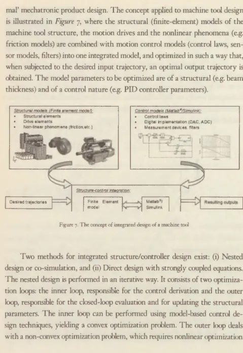
ized in a so-called ‘mechatronic compiler’. A mechatrmic compiler transforms a set of high-level design requirements in a semi-automatic way into an ‘opti-
H E N D R IK V A N B RU SSE L: A S Y S T E M S A P P R O A C H T O M A N U F A C T U R IN G S C IE N C E ■7
mal’ mechatronic product design. The concept applied to machine tool design is illustrated in Figure 7, where the structural (finite-element) models o f the machine tool structure, the motion drives and the nonlinear phenomena (e.g.
friction models) are combined with motion control models (control laws, sen
sor models, filters) into one integrated model, and optimized in such a way that, when subjected to the desired input trajectory, an optimal output trajectory is obtained. The model parameters to be optimized are of a structural (e.g. beam thickness) and of a control nature (e.g. PID controller parameters).
Structural models (Finite element model):
• Structural elements
• Drive elements
• Non-linear phenomena (friction,etc.)
Struct ure-control integration:
Control models (Matlab9/SimulinK):
• Control laws
• Digital implementation (DAC, ADC)
• Measurement devices, filters
Desired trajectories Finite Element
model
Matlab / Simulink
Figure 7. T h e concept o f integrated design o f a machine tool
Tw o methods for integrated structure/controller design exist: (i) Nested design or co-simulation, and (ii) Direct design with strongly coupled equations.
The nested design is performed in an iterative way. It consists of two optimiza
tion loops: the inner loop, responsible for the control derivation and the outer loop, responsible for the closed-loop evaluation and for updating the structural parameters. T he inner loop can be performed using model-based control de
sign techniques, yielding a convex optimization problem. The outer loop deals with a non-convex optimization problem, which requires nonlinear optimization
1 8 S Z E K F O G L A L O K A M A G Y A R T U D O M A N Y O S A K A D E M IA N
methods or the use of genetic algorithms. The nested design strategy converges when the outer optimization loop converges. The interacting structural and con
trol software can use their own integration step, which might be beneficial in reducing calculation time. The direct design strategy considers, simultaneously, the control and structural parameters using a numerical method, such as non
linear optimization algorithms or genetic algorithms. These algorithms may re
quire long calculation times, especially when several parameters are considered, and because there can be only one integration step, that of the fastest process.
5.1. Examples
Example 1: Integrated design o f a 3-axis machine tool [7,8]
T h e design starts with a conceptual design phase, where a variant analysis is made by combining elementary building blocks, and optimal configurations are sought satisfying performance criteria such as maximal workspace, maximal static and dynamic stiffness. In the ensuing detailed design phase, detailed finite-element models are made of the parameterised building blocks and a reduced state-space model, based on C M S (Component Mode Synthesis), is extracted, usable for control purposes. Finally, an integrated structural/control model is used for simultaneously optimising both the controller parameters and some structural parameters.
Example 2: Design o f mechatronic systems with configuration dependent structural dynamics [9,10 ]
Tw o types of mechatronic systems with configuration dependent dynamics are considered: (i) a Cartesian 3-axis pick-and-place robot (Figure 8a), and (ii) a pa
rallel kinematic ultrafast pick-and-place robot (Figure 8b). Structural modell
ing of the Cartesian robot goes in three steps: (i) elaborate a parameterised high-order finite-element model, (ii) extract local linear models at several
H E N D R IK V A N B RU SSE L: A S Y S T E M S A P P R O A C H T O M A N U F A C T U R IN G S C IE N C E
>9
Figure 8. Cartesian pick-and-place robot (a), ultra-fast 2D pick-and-place robot (b)
discrete configurations using a linear model reduction technique, (iii) build an L P V state-space model by affine interpolation between poles, zeros and gains extracted from the reduced models. A mechatronic design approach was applied, using as design parameters: (i) the diameter of the z-axis quill, and (ii) the parameters of the controller, a PID controller in this case. An L T I PID controller is optimised, or a gain scheduling L P V PID controller. The Total Variation (T V ), a time domain metric, has been adopted as performance criterion. When the optimisation is run for different quill diameters, the optimal quill diameter leading to the overall minimal T V of the end effector, over all z-positions of the quill, can be determined.
The objective for the parallel kinematic robot is to move the end effector according to a predefined trajectory in the plane, with accelerations reaching 300111/s2. The control structure is a typical feedback configuration, complemented by a feedforward input to guarantee accurate tracking of the reference trajectory. The mechanical structure is modelled as a flexible multibody system, on which the classical model reduction techniques are applied. T he feedforward signal is spline based, the parameters of which are to be optimised to ensure accurate tracking. The structural parameters taken
20 S Z F K F O G L A L O K A M A G Y A R T U D O M A N Y O S A K A D E M IA N
into account in the integral design approach are the lengths of the inner and outer arm of the manipulator. The aim is to evaluate the tradeoff between the maximal required torque of the drive motors and the tracking error.
Example 3: Optimisation o f the comfort o f a passenger car
The aim of the application of the integrated design approach was to optimise the comfort of an Audi car provided with Tenneco semi-active dampers. Multibody modelling was done using a symbolic modelling package (RO BO TRAN ), followed by finite-element modelling (M EC A N O /O O FELIE). This model was integrated with a control model and optimised when subject to a stochastic road input and with the R M S acceleration of certain points on the car body as performance criterion.
6
. CONTROLLING MECHATRONICS SOCIETIES
The discussion above shows the advantages and even the necessity of an integrated view on design and control of simple or complicated mechatronic systems. Mechatronics societies, such as manufacturing plants, are complex systems. They require other design and control rules, able to cope with the inherent uncertain behaviour of these systems and to guarantee robustness and allow for easy extendibility.
Complex manufacturing systems are considered as holovic systems, consisting of interconnected holms. Holom [11] are autonomous agents, cooperating with each other to achieve a global system goal. A consequence of this definition is that, in order to be a holon a subsystem, eventually consisting o f several holons, must be of sufficient size to be stable and behave autonomously [12], and equipped with appropriate interfaces to
H E N D R IK V A N B R U SSE L: A S Y S T E M S A P P R O A C H T O M A N U F A C T U R IN G S C IE N C E 21
be able to communicate with all the other holons in the system, also with holons to be added later. Holons only have local expertise and intelligence.
Holonic ?nanufacturing systems are meant to exhibit the advantages of hierarchical systems, working strictly according to predefined process plans, but able to work optimally as long as no contingencies occur, and of heterarchical systems, working purely based on interactions and hence are very flexible and robust, but not optimal.
6.1. The PROSA reference architecture [13]
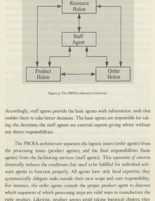
T he PROSA reference architecture (Figure 9 ) describes a generic way of building holonic (manufacturing) system models. It is built around three types o f basic holons (agents): order, product and resource holons. Each of them is responsible, respectively, for one aspect of manufacturing control: (i) internal logistics, (ii) recipes or process plans, and (iii) resource handling. These basic agents are structured using object-oriented concepts like aggregation and specialization.
S ta ff agents can be added to assist the basic agents with expert knowledge (e.g. a scheduler). Each resource agent corresponds to a production resource in the manufacturing system and contains an information processing part that controls the resource. Each product agent owns a “product model” of a product type — not the “product state model” of one physical product instance being produced. A product agent acts as an information server to the other agents, delivering the right recipes in the right place. Each order agent represents a task. It is responsible for performing the corresponding work correctly and on time. It manages the physical product(s) being produced, the product state model, and all logistic information processing related to the job. The staff agent mirrors the difference between line functions and staff functions in human organizations. In a human organization, one of the main goals for the intro
duction of staff functions is to reduce the workload and complexity of line functions (or operational processes) by providing them with expert knowledge.
22 SZ E K F O G L A L O K A M A G Y A R T U D O M A N Y O S A K A D I-'M IA N
Figure 9. T h e PRO SA reference architecture
Accordingly, staff agents provide the basic agents with information, such that enables them to take better decisions. The basic agents are responsible for tak
ing the decisions; the staff agents are external experts giving advice without any direct responsibilities.
The PROSA architecture separates the logistic issues (order agents) from the processing issues (product agents), and the final responsibilities (basic agents) from the facilitating services (staff agents). This separation o f concerns drastically reduces the conditions that need to be fulfilled for individual soft
ware agents to function properly. All agents have only local expertise; they systematically delegate tasks outside their own scope and core responsibility.
For instance, the order agents consult the proper product agent to discover which sequences of which processing steps are valid ways to manufacture the right product. Likewise, product agents avoid taking logistical choices; they
H E N D R IK V A N B R U SSE L: A S Y S T E M S A P PR O A C H T O M A N U F A C T U R IN G S C IE N C E 2 ?
make all known possible processing sequences available for the order agents.
Furthermore, order agents query resource agents about expected processing times, whereas product agents query resource agents about the supported manufacturing process types. In this manner, the design of the agents avoids introducing unstable choices. Staff agents give advice only. This reduces the constraints imposed by the design of the staff agents toward the remainder of the system. It also avoids the build-up of inertia for the design choices in the staff agent designs.
6.2. Holonic (manufacturing) execution system (HMES) [14, 15]
The PROSA reference architecture allows describing complex systems in an easily scalable way. PROSA describes the different holons along the lines of essential modelling, known from object-oriented programming. PROSA builds structural models rather thanfunctional models. Consequently, it does not describe the ‘dynamics’ (control) of the system to execute a task, defined by the order holon. An additional task execution system is needed to control the system described by PROSA.
Control (task execution) of holonic systems is preferably based on interactions, rather than on transactions by rigid algorithms (A route description [algorithm], provided by a route planner is less robust against disturbances [e.g. a roadblock], than a map [interactive]). In such an interactive task, system control emerges from the interactions between the (intelligent) product holons and (intelligent) resource holons, described in PROSA, needed to appropriately execute the task defined by the order holon. Taking manufacturing as an example, a holonic manufacturing execution system (HM ES) tries to improve the responsiveness, proactivemss, scalability and flexibility of the manufacturing system and handles changes and disturbances as business as usual.
24 SZ feK FO G L A L O K A M A G Y A R T U D O M A N Y O S A K A D F M IA N
The H M E S described hereunder is bio-inspired. T he world of social insects provides a rich source of inspiration for the design of complex adaptive systems. The food foraging behaviour in ant colonies constitutes an interesting example and is adopted here. Ants coordinate each other’s behaviour through signs in the environment; this is called stigmergy. Ants observe signs in their environment and act upon them without synchronization with other ants.
Most interesting is that local signs inform the food foraging ants about global properties of the system. Importantly, these signs are put in the environment without exposing individual ants to the complexity and the dynamics of the situation.
Food foraging ants execute a simple procedure: (i)In the absence of any signs in the environment (consisting of scents from a pheromone), ants perform a randomized search for food, (ii) W hen an ant discovers a food source, it drops a smelling chemical substance — i.e. pheromone — on its way back to the nest while carrying some of the food. Thus, it creates a pheromone trail between nest and food source. An important property of such pheromone trail is that it will evaporate if none of the ants deposes fresh pheromones. (iii)When an ant senses a pheromone trail, it will be urged by its instinct to follow this trail to the food source. Note that a scent strength gradient indicates the direction toward the food. (iv)When this ant arrives at the food source, it will return with food, while depositing more pheromones. In this manner, the strength of the pheromone trail is maintained and even reinforced. When the ant finds an exhausted food source, it starts a randomized search for a new food source and the trail disappears because of the evaporation.
The above scheme results in an emergent overall behaviour for the colony that is highly ordered and very effective at foraging food. At the same time, it is robust against the uncertainty and complexity posed by the environment.
An important capability of this type of stigmergy is that global information
H E N D R IK V A N B RU SSE L: A S Y S T E M S A P P R O A C H T O M A N U F A C T U R IN G S C IE N C E 2 <-
— about where to find food in a remote location — is made available locally
— i.e. the direction in which the ant must move to get to this food. The main achievement is that individual ants are not exposed to the complexity and dynamics of the situation. Instead, the environment is incorporated into the solution and allows the overall system to cope with its complexity; none of the ants needs a mental map of the environment. Similarly, the evaporation and refreshing of the pheromone trails allow the ants to cope with the dynamics o f the environment; there is no information in the head of the ants that must be kept synchronized with reality. This ant colony design avoids introducing coordination mechanisms that fail when the environment changes or that break when the geometrical complexity of the environment grows.
Moreover, pheromone trails that become invalid are no longer refreshed and evaporate. ‘Evaporation and refresh' is a generic mechanism to limit the inertia of information that is accumulated over time.
Ant colonies and PROS A
The ant colony H M E S applied here is based on the addition of delegate multi- agent systems (delegate M AS) to its order holons. A delegate M A S consists of a swarm o f lightweight agents (called ant agents) that provide a service for a heavier agent (the issuing agent) to support this agent in fulfilling its functions.
For resource allocation and production/logistic activity coordination, two distinct delegate M A S are employed: a swarm of exploration ants that seek out possible routings amongst resources on behalf of a task, and a swarm of intention ants that communicate a task’s likely routing back to the resources.
The issuing agent controls the number of ant agents, their program, and their parameter settings.
'The ants in a delegate M AS deposit, observe, and modify information (digital pheromones) in the virtual counterpart of the real world (i.e. the persistent model network). This information can be any kind of data structure.
26 S Z E K F O G L A L O K A M A G Y A R T U D O M A N Y O S A K A D E M IA N
Moreover, the environment in which the information is deposited may transform this information. For instance, bookings made by intention ants are inserted into a resource agent’s planning scheme. All pheromone information has an expiration time (evaporation). A delegate M A S delegates in two manners.
First, the issuing agent assigns a responsibility to the delegate MAS. Second, the ant agents delegate to the environment in which they travel and evolve.
For instance, exploration ants query resource agents about expected processing times, processing results, transportation times, etc. Intention ants delegate the local scheduling to the resource agents. Exploring ants use product agents to evaluate routing options. This extreme usage of delegation enables a delegate M A S to cope with a dynamic, heterogeneous and unpredictable world; it is instrumental in avoiding model contamination. Its design nowhere assumes that data structures suffice to capture the diversity of the problem domain.
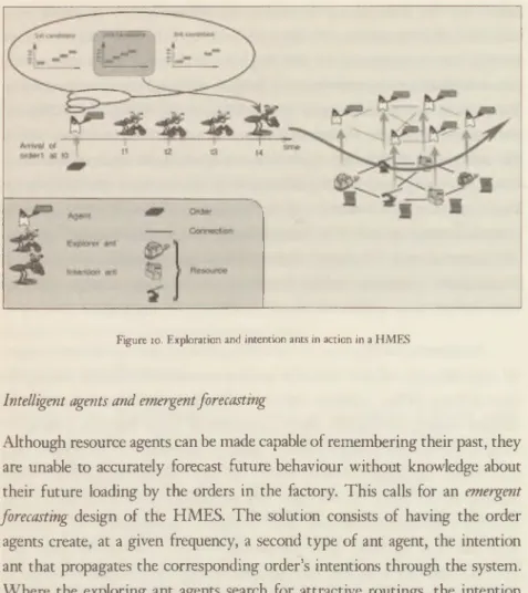
As illustrated in Figure 10, the smaller exploration ants are created at regu
lar time intervals and each virtually executes a possible and feasible routing for their activity. W hen sufficient exploration has been done (determined by the decision-making mechanism model), the activity holon executes a decision
making mechanism model to select a solution (discovered by an explorer ant) and creates the bigger intention ant to virtually execute this solution while making the necessary reservations. The exploration process continues even after the reservations have been made to discover opportunities for improve
ment and to be prepared when disturbances occur. The activity holon cre
ates intention ants at regular time intervals to compensate evaporation and to discover whether the situation has changed. The evaporate-and-refresh o f the digital pheromones by these delegate M AS keep the agents’ view on the world- of-interest up to date. T he extreme delegation obeys the single source o f truth principle and makes the overall system model-driven.
H E N D R IK V A N B RU SSE L: A S Y S T E M S A P P R O A C H T O M A N U F A C T U R IN G S C IE N C E 2 7
Figure 10. Exploration and intention ants in action in a H M E S
Intelligent agents and emergent forecasting
Although resource agents can be made capable of remembering their past, they are unable to accurately forecast future behaviour without knowledge about their future loading by the orders in the factory. This calls for an emergent forecasting design of the H M ES. The solution consists of having the order agents create, at a given frequency, a second type of ant agent, the intention ant that propagates the corresponding order’s intentions through the system.
Where the exploring ant agents search for attractive routings, the intention ant agents propagate the currently selected route of their order agent. These intention ant agents navigate virtually through the factory and inform resource agents about the intention of the order to visit the resource. Again, these ant agents retrieve all performance and topology information through querying the resource agents. This enables them to predict how long it will take to travel or to be processed without exposing themselves to software maintenance
28 S Z F .K F O G L A L O K A M A G Y A R T U D O M A N Y O S A K A D F .M IA N
problems when changes or disturbances occur in the factory. Likewise, they execute the decision module o f the order agent, while feeding this module forecasted information. In contrast to the exploring agents, the intention ant agents inform the resource, which they visit on their virtual journey, about their intention to actually execute this routing. The resource agents record this declared intention and use it to update their own local load forecast. In other words, the resource agents construct a workplan (a kind of G A N T T chart) for their resource out o f the intentions that have been declared to them by the intention ant agents on behalf of the order agents. In this manner, the multi
agent system realizes emergent short-term forecasting. A built-in evaporation/
refresh mechanism ensures that old intentions disappear and are replaced by new ones. The refresh also informs the order agents about changes in the perfor
mance of the current intentions. Indeed, when a resource breaks down, or a rush order is scheduled in front of this order, the intention refresh will reveal the impact on performance for the affected orders. W hen the exploring ant agents report back more attractive routes, the order agent is likely to change its intentions, thus reacting to the deterioration of its current intentions or the discovery of a more attractive routing by the exploring ants.
Socially acceptable behaviour [16 ]
The accuracy of the emergent forecasts depends on the behaviour of the order agents. When order agents strongly stick to previously declared intentions, the manufacturing system will be unable to respond to disturbances, and it is likely to become locked into the (sub-optimal) routings that were explored first.
Conversely, if order agents modify their intentions whenever the perceived performance o f an alternative routing is slightly better than the perceived performance of the current intentions, the system will behave chaotically and the forecasts will be useless. To avoid these undesirable constraints, the order agents’ decision mechanism is encapsulated in a wrapper that enforces
11F.N D RIK V A N B RU SSEL: A S Y S T E M S A P P R O A C H T O M A N U F A C T U R IN G S C IE N C E 2 0
socially acceptable behaviour. This wrapper enables the designer to configure the nervousness of the order agents. The proper decision mechanism provides the wrapper with its preferences (i.e. perceived performance of the possible decisions) and the wrapper decides about changing intentions. This changing will be probabilistic, such that only a small percentage of affected order agents react to a given disturbance before the refresh makes the consequences of these changes visible to the other agents. In addition, this wrapper imposes further constraints, such as sticking more to intentions that are in the near future than to those that are further away in time, or a minimal time in between changes of an order’s intentions. Moreover, different types of orders can have different behaviours (e.g. rush order versus make-to-stock orders).
6.3. Application Domains of HM ES
The H M E S concepts are more generally applicable than just manufacturing.
This section gives an overview from several cases where the concepts and principles of the H M E S have been applied.
Manufacturing - A car paint shop [17 ] (Figure u )
A car body paint shop was an excellent case to test the applicability of the H M E S for flexible floiv shops. This large shop, comprising six floors, paints more than 1000 car bodies each day and comprises more than 400 manufacturing resources: unidirectional and bi-directional conveyors, turning tables, lifts, painting booths, etc. These resources are arranged in a complex topology, in which loops are present. The system has built-in redundancy, i.e.
for each processing step multiple resources can be chosen. Similarly, for the transportation more than one routing option is available to move a car body from one processing unit to the next. As the result of a production step is uncertain, the next processing step for a car body will depend on the outcome of the previous one. This means that it is sometimes necessary that a product
30 S Z E K F O G L A L O K A M A G Y A R T U D O M A N Y O S A K A D F M IA N
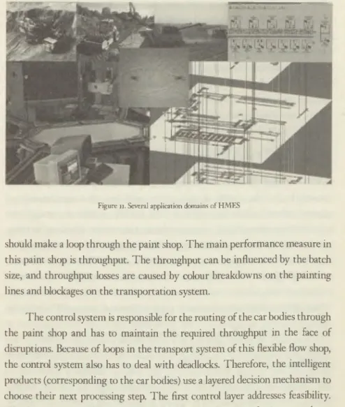
Figure i i. Several application domains o f H M E S
should make a loop through the paint shop. The main performance measure in this paint shop is throughput. The throughput can be influenced by the batch size, and throughput losses are caused by colour breakdowns on the painting lines and blockages on the transportation system.
T he control system is responsible for the routing of the car bodies through the paint shop and has to maintain the required throughput in the face of disruptions. Because o f loops in the transport system of this flexible flow shop, the control system also has to deal with deadlocks. Therefore, the intelligent products (corresponding to the car bodies) use a layered decision mechanism to choose their next processing step. T he first control layer addresses feasibility.
This layer is responsible for deadlock avoidance and ensures for instance that a car body is not transported in a direction which lacks the necessary processing capabilities. The second layer handles production goals like maximizing throughput or respecting due dates. A third layer can provide advisory
IIK N D R IK VA N BRU SSF.L: A S Y S T E M S A PP R O A C H T O M A N U F A C T U R IN G S C IE N C E i !
information. These layers are application specific and can be easily replaced if necessary (plug-ins). T he control system is also responsible for the batching of the car bodies for the painting process. Small batch sizes lead to more setups and so a lower throughput. Moreover, as batches are small, there are more defects and so more car bodies have to be repainted, lowering the throughput even more. To deal with this, the intelligent resources corresponding to the painting equipment propagate information about their planned batches (size, colour, time window, etc.). The intelligent products can use this information to decide to join a certain batch.
Manufacturing - Flexible manufacturing system (F M S ) [14 ,18 ] (Figure n )
Another application addressed a machine shop producing long components of weaving looms. The shop floor is organized as a job shop with a central automated storage and retrieval system (AS/RS). This AS/RS consists of a storage area and an automated rail-based transporter, called the ‘tram’, to pick up and drop off loads at the various workstations. T he components are transported in containers. Each container contains a variable number of identical components, travelling together until completion. At the workstations, the components of a container are processed one by one and put in another (empty) container.
When all components are processed, the transporter is prompted to bring the container to the storage area. T he transporter can carry two containers at the same time. So, before moving to a workstation to pick up a container, the transporter can travel to the storage area to take the container that has to be processed next at that workstation. In this way, an additional movement of the transporter is avoided. Most of the processing steps (e.g. sawing, milling, turning, etc.) can be carried out by several alternative workstations, but possibly with different processing times.
The H M E S has to organize the production by routing the containers - represented by intelligent products - through the machine tool shop. T he vari
32 S Z E K F O G L A L O K A M A G Y A R T U D O M A N Y O S A K A D E M IA N
ous (intelligent) resources (workstations, storage area, transporter ...) offer their operations as services to the intelligent products. The considered perfor
mance criteria are: throughput increase, lead-time minimization, improvement of labour and resource utilization. Another important issue for the control sys
tem is the optimization of the use of the transporter. During periods of heavy demand for transportation (rush hour), the transporter is a bottleneck and causes workstations and operators to idle.
Open- A ir Engineering [19 ] (Figure 11)
T he concepts o f the H M E S can equally well be applied to coordinate open-air engineering processes such as open-pit mining, road construction and harvesting (see Fig. 12). These processes are usually carried out with high-tech mobile equipment (e.g. excavators, dump trucks, asphalt layers, road graders) that need to cooperate in order to execute the processes successfully. As the operating costs of the work vehicles are considerable, it is important to optimize their productivity through proper planning and execution of their operations. This involves resource allocation and scheduling decisions, aiming to optimize one or more performance objectives (e.g. minimizing completion time or energy consumption). T he dynamics in the open and distributed operating environment o f open-air engineering processes make this planning complex.
’ Current approaches see this problem as a resource constrained project planning problem for which a large number of mathematical and ad-hoc heuristic techniques have been developed. The planning is performed off-line before the process starts. Changes in the operating environment require re
planning.
In an H M E S for open-air engineering processes, the intelligent resource agents correspond to the work vehicles, as well as to stationary physical entities (e.g. storage bins for excavated product). These intelligent resources
H E N D R IK V A N B RU SSE L: A S Y S T E M S A P P R O A C H T O M A N U F A C T U R IN G S C IE N C E 33
offer domain-specific services such as excavating, harvesting, transporting, etc. Also, these resources contain models of their corresponding reality that encapsulate the domain-specific aspects. These models are used to make short
term forecasts, for instance to predict when a storage bin’s capacity will be reached. The processes that have to be carried out are the intelligent products, looking for services from the intelligent resources to get their task executed.
Specific for this case is that a product sometimes needs multiple services and resources at the same time (multi-resource allocation). For instance, in open-pit mining, to mine a certain area, the service of an excavator is required, together with the service of a dump truck to transfer the excavated product.
Robotics [20]
Applying the H M E S concept is also relevant for multi-robot coordination.
Consider a set of robots navigating in the same environment, each having its own goal location. T he robots should autonomously move around and use range sensors to detect and avoid obstacles. Navigation should be smooth and interference with other robots or humans should be minimized. A possible scenario is in a hospital or retirement home where a limited number of robotic wheelchairs should provide autonomous navigation for a large number of patients or inhabitants. These users would request a wheelchair (through some interface) and the robot would then navigate autonomously to the user. After the user is assisted into the wheelchair, a target location is given, towards which the robot has to navigate. T he benefit of this approach is that medical staff is only required, when the user wants to mount or dismount the wheelchair. W hile navigating, the robot autonomously finds its way and is able to avoid obstacles using its range sensors. In this scenario, the need for smooth navigation and low interference is apparent. Minimizing the patient’s discomfort is a key criterion for a successful application. In a more industrial context, this application would be useful in allowing a set of autonomously
34 S Z E K F O G L A L O K A M A G Y A R T U D O M A N Y O S A K A D E M IA N
guided vehicles (AGVs) to transport goods from one location in a warehouse to another.
In a traditional robocentric approach, each robot executes its own task, assuming the environment is implicitly allocated for its needs and not being aware that other users might be present. Users can either be humans moving around or other robots executing a task. Each room is connected to two narrow corridors and depending on the target, going through one corridor is more efficient than going through the other. This scenario can cause livelocks, provided the number of robots is high. A more common problem, however, is that the robots do not follow an optimal path to move from one room to another. I f two robots enter the same corridor and are not aware of each other’s intention, they will most likely replan their route through the other corridors in order to reach their target, resulting in a longer travel path.
The main contribution of using the H M E S concepts in the context of robotics is that rooms and corridors are represented by intelligent resources, and are thus treated as first class citizens in the overall software system. Most other robot software architectures (such as [i, 16]), on the other hand, adopt a functional decomposition and the representation of the environment is spread over the different control systems (each robot maintains its representation).
The structural decomposition adopted in H M E S improves scalability and flexibility, since explicit resource allocation allows taking other robots’ intentions into account.
Another contribution toward the robotics domain is the introduction of short-term forecasting in multi-robot navigation. The delegate M A S provides a way to adopt the robot’s behaviour in such a way that it optimally takes into account future tasks or conflicting tasks o f other robots. Consider for instance a small corridor, only wide enough for one robot to pass simultaneously.
H E N D R IK V A N B R U SSE L: A S Y S T E M S A P P R O A C H T O M A N U F A C T U R IN G S C IE N C E 35
Turning this corridor into an intelligent resource with explicit allocation allows forecasting whether or not it is opportune to navigate through this corridor.
In the robotics context, the intelligent products correspond to the tasks a robotic platform or a fleet o f robots need to execute. In the navigation scenario, this boils down to a sequence of navigation operations to move from one location to another. All physical entities supposed to execute a particular task are represented by intelligent resources, e.g. robotic platforms, sensors in the building, doors, corridors, etc. Representing a physical robot by an intelligent resource allows including the robot’s available services, such as navigation or manipulation.
Logistics - Chain Conveyor System[2i]
Chain conveyors are often used for the internal transportation of goods, for instance in distribution centres. In many cases, several chains are connected to each other (by means of diverters) to form a complex transportation network.
The control system has to decide about the routes that products follow and when these products are transported. Moreover, the control system has to deal with uncertainties and disturbances (e.g. defect carts, delays, jammed chains, etc.). Currently, chain conveyor systems are controlled statically. Routing tables determine the route for each product type. These tables are only adapted when serious changes happen, for instance when the product mix changes drastically.
As all products from the same category follow the same route through the system, the control system has no flexibility and cannot react to disturbances.
By applying the H M E S concepts, the control can be made more flexible and dynamic. The different components of the chain conveyor system (e.g.
the chains and diverters) are represented by intelligent resources which have a model of the behaviour of the corresponding component. Such a model of a chain for instance can forecast when a cart will reach a certain position.
36 SZ E K F O G L A L O K A M A G Y A R T U D O M A N Y O S A K A D F.M 1A N
The intelligent products correspond to the goods that have to be transported by the chain conveyor system, and they search for the necessary services like transporting and switching to get their corresponding product at the required destination. In contrast to the static approach, each product can now follow an individual route through the conveyor system and can react to disturbances such as a jammed chain (responsiveness). The short-term forecasts even allow anticipating certain disturbances (e.g. a congested chain) and to find an alternative route (proactiveness).
Logistics - Cross-Docking Facility[22 ]
Cross-docking is a logistic strategy in which incoming shipments are (almost) directly transferred to outgoing trailers, with little or no storage in between.
I f the shipments are temporarily stored, this should be only for a short period of time, e.g. less than 24 hours. Cross-docking can have several advantages:
the consolidation of shipments, shorter delivery lead times, cost reduction, etc. However, the organization of the cross-docking operations is a complex and challenging task, certainly because the arrival and departure times of the inbound and outbound trucks need to be synchronized. Moreover, cross-docks operate in an uncertain and dynamic environment, among others due to a tough competition in the transport and logistics sector and an ever-increasing traffic.
T he current approaches to control a cross-dock are usually planning approaches, in which the plan is made off-line before the operations start.
These approaches usually assume that all necessary information (e.g. the exact content and arrival time of the incoming trucks) is fixed and known beforehand.
Also, the problems are usually assumed to be static, while the control of a cross
dock is inherently dynamic (trucks arrive early or late, equipment fails, etc.).
H E N D R IK V A N B RU SSEL: A S Y S T E M S A P P R O A C H T O M A N U F A C T U R IN G S C IE N C E 37
W hen using H M E S to control a cross-docking terminal, all trucks, forklifts and dock doors become intelligent resource agents. This intelligent resource contains a model of the dynamic behaviour of the corresponding real- world resource so that what-if questions can be answered. It is also responsible for its own local decisions (e.g. a dock door should decide which truck it handles). All goods that have to be handled in the cross-dock are represented by intelligent products. These intelligent products are responsible for routing their corresponding entities through the cross-docking system. Therefore, they can make use of the available services offered by the intelligent resources, such as loading or unloading, internal transportation, temporary storage, etc.
Also for this application, multi-resource allocation is an issue. For instance, when goods have to be unloaded from a truck, these goods require the unload service from a forklift (and a driver), while at the same time the truck and a dock door have to be available (these resources also have to be allocated, even if they do not perform an active service in this situation).
7. CONCLUDING REMARKS
Ongoing industrial and societal paradigm shifts require a systems approach to designing intelligent products and meta-products. Mechatronics is the in- tegrated-design paradigm par excellence to design high-performance products.
Mechatronics societies require a distributed multi-agent control approach, eventually bioinspired, to ascertain robustness, scalability, proactiveness, and socially accepted behaviour.
38 S Z E K F O G L A L O K A M A G Y A R T U D O M A N Y O S A K A D K M IA N