Virtual Design of Advanced Control Algorithms for Small Turbojet Engines
Ladislav Főző
1, Rudolf Andoga
2, Levente Kovács
3, Michal Schreiner
2, Károly Beneda
4, Ján Savka
1, Radovan Soušek
51Department of aviation engineering, Faculty of Aeronautics of Technical University of Košice, Rampová 7, 04001 Košice, Slovakia
ladislav.fozo@tuke.sk
2Department of avionics, Faculty of Aeronautics of Technical University of Košice, Rampová 7, 04001 Košice, Slovakia
rudolf.andoga@tuke.sk, michal.schreiner@tuke.sk
3John von Neumann Faculty of Informatics, Óbuda University Bécsi út 96/b, H-1034 Budapest, Hungary
kovacs.levente@nik.uni-obuda.hu
4Department of Aeronautics, Naval Architecture and Railway Vehicles, Faculty of Transport Engineering, Budapest University of Technology and Economics, Műegyetem rkp. 3, H-1111 Budapest, Hungary
kbeneda@vrht.bme.hu
5Faculty of Transport Engineering, University of Pardubice Studentská 95, 53210 Pardubice, Czech Republic
radovan.sousek@upce.cz
Abstract: Advanced control in the area of turbojet engines defines many different applied complex control strategies. Highly theoretical approaches and designs are often presented in this area. The article is aimed at practical aspects of adaptive controller design for a class of small turbojet engines in triple loop control architecture. The article presents a non-linear dynamic model of a small turbojet engine taking in account the environmental conditions, which it operates in. The designed triple loop control architecture shows increased precision of control keeping acceleration schedule of the simulated engine and is not susceptible to outer disturbances. The article shows pilot dynamic simulation tests, showing feasibility of the taken approach. It can also be used for other classes of turbojet engines as well other similar technical systems.
Keywords: turbojet engines; adaptive control; non-linear system; dynamic modelling
1 Introduction
Control systems of aircraft engines define their economic and operational efficiency as well as their safety. Digital control systems allow updating control algorithms as software packages, which can quickly and effortlessly improve fundamental operational characteristics of an engine. There are many approaches, which are today applied to fulfil this task [1, 2, 3, 4]. Apart from the classical PID control systems, which are quite effective [5, 6], more progressive approaches in control of turbojet engines can be taken [7, 8]. The ones, which expand on the classical control schemes are the adaptive control algorithms [8, 9, 10].
This means application and design of a controller, which is using some sort of adaptation not only to outer environmental conditions but also to state conditions of a turbojet engine, contrary to control systems using non-adaptive controllers with integrated limiters [5, 6]. Such approach can achieve a solid control quality and safety of operation in turbojet engines control and is today widely used and improved [11, 12, 13, 14].
Small turbojet engines usually use simple control algorithms. The aim of the paper is to show the advantage of combining an adaptive algorithm with a triple loop control architecture, which keeps acceleration/deceleration schedules of the engines steady throughout their whole operational life [7]. This is not typical for small turbojet engines, but it can be expected that combination of adaptability and multi-looped control system can be very efficient for this class of engines.
In order to show the advantages of adaptive and multi loop control in the area of small turbojet engines a non-linear simulation model has been developed taking in account altitude and velocity parameters and their influence on a small turbojet engine. The article covers a practical approach in adaptive controller design using a generalized non-linear engine model and shows advantages of such approach in control of small turbojet engines compared to traditional control approaches using fixed parameters PID controllers with limiters [7, 17, 18]. This practical approach is contrary to often presented results, which are only concepts or strictly simulation results [4, 5, 15, 17]. The resulting design should provide a controller design that is suitable for acceleration/deceleration control as well as steady state control in a wide area of changing aircraft velocities, altitudes and engine speeds with good efficiency [17].
2 Non-Linear Model of a Small Turbojet Engine
2.1 A Generalized Dynamic Engine Model
In order to design and test an adaptive control scheme for a turbojet engine, a generalized dynamic turbo-compressor model based on available data of the turbo-compressor TJ/TP 100 engine has been developed. The model also includes a dynamic actuator model and together with a non-linear approximation of speed/altitude characteristics [18, 19, 20].
The model can be expressed as the following transfer function after Laplace transformation:
) , , ( ),
, , ( 1 ,
) (
)
( K f n H M T f n H M
s T
K s
FF s n
e e
e
e
(1)Where:
FF – fuel flow [l/min],
n – rotational speed of the engine [RPM],
Ke – static gain of the engine,
Te – time constant of the engine [sec],
H – flight altitude [m],
M – Mach number [-],
f – a non-linear approximation function.
The first order transfer function is able to approximate the dynamics of the engine with sufficient precision [2, 18], its complexity is hidden mainly in the non-linear characteristics of its Ke and Te variables. Both reflect the changes in outer environmental conditions and the engine’s state conditions. These non-linear characteristics have been modelled according to data from TJ-100 engine. The graph in Figure 1 presents a non-linear approximation of the Ke parameter for the different engine’s speeds, altitudes and velocities. The graph in Figure 2 shows approximation of the Te parameter for the same input parameters. These approximations can be considered as valid for different engines. The equations used for these approximations are defined as follows (2) (3):
0 2 5
. 2 3 0 0
2 . 0 1 2
. 0
1 T
M T
M p
T p
T
HH p e
(2)
0 2
3.50
p 1 0 . 2 M K p
K
H p
e
(3)where Tpo and Kpo are obtained from equilibrium states of the engine at ground conditions at temperature and pressure for static ground conditions defined as T0=288°K and p0=1.013e05 N/m2. The parameters TH and pH were defined using the international standard atmosphere (ISA) model [23]. The flight altitude is changing in the interval
H 0 , 4000
m and Mach number in the intervalM 0 , 0 . 4
.Figure 1
Approximation of the gain “Ke” parameter
Figure 2
Approximation of the time constant “Te” parameter
2.2 Architecture of the Model
The resulting model has a single input control parameter (fuel flow supply), two input outer/environmental parameters (Mach number and Altitude) and one state parameter, which is the rotational speed of the turbo-compressor. The state parameter represents a feedback in the model to approximate Te and Ke parameters of the model.
Figure 3
The architecture of the engine model
Dynamic response of the engine is also considerably influenced by dynamics of the fuel pump with a non-linear element by-pass valve [2, 9, 21]. Transfer function of the valve can be expressed by the transfer function Fbypass (n), its operation being dependent on the engine’s speed n. Fuel flow is partially transferred back into the engine up to a speed around 50 000 RPM. The resulting transfer function of the fuel pump with the non-linear function of the bypass valve is presented in the equation (4):
) ) (
( )
( F n
s PWM
s
F
FFPWM FF
bypass (4)The control input of the fuel pump is a pulse width modulated signal PWM, output of the pump is given by its mass fuel flow. The dynamic simulation model of the engine and its fuel flow pump with the bypass valve is shown in Figure 4.
Figure 4
The model implemented in simulation environment
The simulation in Figure 5 presents a dynamic response of the engine’s model to a step in the fuel flow supply at different altitudes running for 10 seconds. The model is able to capture dynamic characteristics of the real engine, it can be seen that with increased altitude its acceleration time is lower and achieved speed is higher with identical fuel flow.
The final model represents a non-linear dynamic system, which changes its characteristics according to different environmental and inner state conditions.
The system is inherently stable as its base is defined by a first order transfer function and a traditional PI controller in a single loop is able to control it successfully. However, its efficiency decreases in off design conditions when altitude or velocity change. In order to secure qualitative control in all conditions with guaranteed acceleration times and constant control efficiency, different adaptive control methodologies will be investigated further.
Figure 5
Dynamic step response of the constructed model
3 Controller Design
In order to meet the strict criteria in acceleration and deceleration times laid on modern turbojet engines, the methodology of n_dot control has been selected [7, 24]. This methodology is today widely used and is aimed at securing constant acceleration times by controlling the acceleration and set-point of the engine using a multiple loop control architecture [5, 6]. In order to decrease the complexity of the controllers a third inner-most loop is devised, which is aimed to precisely control and meter the fuel flow. The triple loop control system architecture is shown in Figure 6. Limiters and the engine protection logic is not considered, but can be added in any of the loops using the min-max methodology or others [25, 26, 27].
Figure 6 Triple loop controller design
The inner-most feedback loop controls the fuel flow supply into the engine by computing the pulse width modulated (PWM) signal controlling the fuel pump with control law defined as follows:
)) ( )
( )(
( )
( s K T s FF s FF s
PWM
d cm d
act (5)The inner-most feedback loop controls the fuel flow supply into the engine by computing the pulse width modulated (PWM) signal controlling the fuel pump with control law defined as follows:
)) ( )
( )(
001 . 0 6625 . 3 ( )
( s s FF s FF s
PWM
cm d
act (6)The next loop contains the n_dot controller, which is used to control the speed derivative of the engine keeping it at constant level until the desired engine speed is obtained. This loop computes the desired fuel flow into the engine to be stabilized by the lower level loop. This loop is crucial for the resulting control quality and is mainly influenced by state and environmental parameters. This means that adaptive control algorithm has to be applied at this level of control.
The control law of this loop is defined as:
. ( ) . ( )
1 ) 1 ( )
( K s ndot s s n s
s T s s
FF
ndot cmdi
cmd
(7)The computed controller for the non-adaptive approach for the designed model is as follows:
. ( ) . ( )
05 9881 . 0.0001 2
1 ) 1
( e s ndot s s n s
s s s
FF
cmd
cmd
(8)The outermost loop computes the derivative command for the engine in order to get to a selected set-point, the commanded rotational speed. The control law at this level is very simple and is defined as:
( ) ( )
)
( s K n s n s
ndot
cmd
setp cmd
act (9)the computed P controller at this level is as follows:
( ) ( )
8 . 0 )
( s n s n s
ndot
cm d
cm d
act (10)3.1 Adaptive Triple Loop Control System
In order to change the dynamics of the system the Kndot parameter of the control law was defined in (7). The dynamics of the control loop is mainly influenced by this parameter and it will be scheduled according the equation:
) , (
e endot
f K T
K
(11)The function f represents the function of the adaptor and Ke, Te are the parameters of the internal model as defined in (1) and Figure 3. The resulting adaptive control system architecture therefore represents an adaptive control system with an internal model [28, 29, 30]. The designed control system architecture is shown in Figure 7.
Figure 7
Adaptive triple loop controller design
Three different approaches when designing the adaptor have been tested. The first one is represented by the Naslin algorithm computation of the controller gain according the formula (12), which the coefficients of the characteristic equation have to satisfy [31, 32]:
1 1
2
.
)
( a
i a
ia
i (12)The coefficient α represents allowed overshoot of the response characteristics of the system and ai are coefficients of the characteristic equation of the linearized model of the engine.
The second taken approach in adaptation of the Kndot parameter is the performance quadratic function of the deviation of acceleration from the commanded engine acceleration according to the following formula:
s. n_cmd(s) - n_act(s)
22 . 1 : K
ndot
f
(13)The third approach in adaptor design is application of a neural network. An offline trained neural network with time delayed inputs trained by the “Scaled Conjugate Algorithm” has been used. The neural network has the following structure:
2 neurons in input layer (Te, Ke),
12 neurons in the first hidden layer, 7 neurons in the second hidden layer,
1 neuron (Kndot) in the output layer.
All of the proposed approaches have been evaluated in the simulation environment in order to execute comparative test analysis with the non-adaptive triple loop control system [33].
4 Evaluation of the Control System
The aim of the evaluation is to test the multiple looped control system and see if it operates normally. The presented tests have to be taken as pilot experiments to show the abilities of the adaptive multi loop control system to operate in a range of simulated conditions. The evaluation will mainly be done in simulated environment with the following experimental set-up.
Mach number M=0, 0.3,
Maximal acceleration schedule = 3000 RPM/s,
Engine set-point schedule represented by a step command from 40 000 RPM to 52 000 RPM, meaning that the engine should accelerate from idle to maximal speed at around 4 seconds,
Altitude is set at the following values: 0, 1000 and 4000 meters.
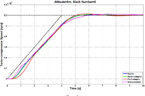
The resulting dynamic responses of the engine in simulations are shown in the following figures. Figure 8 shows the engine‘s acceleration at ground at zero velocity. This also simulates laboratory conditions and can be used for comparison of the simulated and a real-world experiment using the engine iSTC-21v. It can be seen that all controllers operate with similar control quality at this level.
Figure 8 Ground simulation
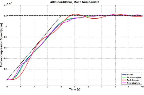
The next simulation resembles a flight of an aircraft at an altitude of 1000 meters shown at a Mach number of 0.3. As shown in Figure 9, with higher altitude the
performance of the adaptive approaches has improved compared to the non- adaptive algorithm, acceleration time of which is slower. It is even more prevalent when the altitude is increased to 4000 meters in Figure 10, where the adaptive approaches show a considerable improvement. On the other hand, it can be stated that all controllers present good control quality keeping the desired acceleration schedule, this means that the turbojet engine is accelerating in approximately 6 seconds irrespective of flight conditions.
Figure 9 Flight at 1000 meters
Figure 10 Flight at 4000 meters
Follow-up simulation tests with constant Mach number M = 0.3 and changing altitude have been done. The summarized performance of all controllers with changing altitude at the constant velocity is shown in Table 1. In order to compare the performance of individual controllers linear absolute control surface have been computed [22]. Lower control surface means that the controller is more efficient in acceleration of the engine. The table shows that the Naslin adaptive controller performs as the best followed by the neural network adaptive algorithm, non- adaptive and the last is the performance quadratic adaptive controller, although it has also achieved acceptable control quality.
Table 1
Comparison of performance between different adaptive controllers Altitude
Adaptor
0 [m] 1000 [m] 2000 [m] 3000 [m] 4000 [m]
Naslin 9295.6 8115.4 7498.8 6750.3 6261.8
Neuro-adaptor 9673.4 8475.3 7807.4 6994.9 6454.6
Perf adaptor 15005 13194 11819 10183 9187.9
Non adaptive 10571 9170.2 8054.1 6978.4 6383.7
To prove the validity of the concept, the triple loop control architecture was employed in laboratory conditions using the iSTC-21v engine [1, 35, 39]. The simulations are compared to the real data obtained in an experiment as shown in Figure 11, where the Naslin adaptor has been employed in the triple loop control system architecture. It can be seen that the experiment with the engine performs
with a lower quality compared to simulations, however it is keeping the schedule well and illustrates that the control concepts presented in simulations can be successfully applied in a digital control system of a real engine. Some further tuning of the designed controller would be needed in order to compensate for other non-linear properties of the engine iSTC-21v, which have not been included in the model. The experiment serves just as a proof of concept that the designed control system is stable and performs similarly to simulations. It needs also to be noted that the adaptive control with triple loop algorithm has been designed for the TJ-100 engine, however, is robust enough to control a different engine.
Figure 11
Comparison of simulation and experimental data using the iSTC-21v engine
Conclusion
A concept for efficient control of a small turbojet engine with fixed exhaust nozzle under different environmental conditions has been shown. Using a triple loop control scheme seems to be a promising concept decomposing the complex controller into several very simple controllers, which can achieve good performance even without adaptation. Adaptation of the middle loop according to a simple Naslin methodology can improve efficiency of the control system further.
Further tuning of the adaptor could probably provide even better results. A practical test has confirmed that the control architecture works in a real experimental setup using the iSTC-21v engine and is robust enough to control different engine than it has been designed for. The practical test serves only as a proof of concept and a more complex set of tests can be done using the modified TJ-100 engine. The design can be implemented in an embedded microcontroller system as envisioned in [34]. More complex neural network with online training and with a broader data-set could improve efficiency of the adaptive control
system even further. A comprehensive set of tests will be prepared and presented as a follow-up study using the TJ-100 engine.
Acknowledgement
The work presented in this paper was also supported by KEGA under Grant No.
044TUKE-4/2019 – “A small unmanned airplane - the platform for education in the area of intelligent avionics.". The work was supported by projects: ESPOSA –
“Efficient Systems and Propulsion for Small Aircraft”, funded by funded by the European commission in the seventh frame work programme under grant agreement no ACP1-GA-2011-284859-ESPOSA and APVV – Slovak Research and Development Agency under grant agreement no. DO7RP-0023-11. The work was support of research and development potential in the area of transport means with ITMS project code: 313011T557.
References
[1] R. Andoga, L. Főző, J. Judičák, et al., “Intelligent Situational Control of Small Turbojet Engines,” International Journal of Aerospace Engineering, Vol. 2018, Article ID 8328792, 16 pages, 2018
[2] G. G. Kulikov, A. Thompson, “Dynamic Modelling of Gas Turbines Identification, Simulation, Condition Monitoring and Optimal Control,”
Springer, p. 337, 2004
[3] R. Hanz, “Advanced Control of Turbofan Engines,” Springer, p. 225, 2012 [4] G. Sanjay, “Controls and Health Management Technologies for Intelligent
Aerospace Propulsion Systems,” Glenn Research Center, AIAA–2004–
0949, NASA/TM—2004-212915, 2004
[5] P. P. Walsh, P. Fletcher, "Gas Turbine Performance", ASME press, Second edition, p. 631, 2004
[6] J. Csank et al, "Control Design for a Generic Commercial Aircraft Engine,"
Glenn Research Center, AIAA–2010–6629, NASA/TM—2010-216811, 2010
[7] L. C. Jaw, J. D. Mattingly, “Aircraft Engine Controls – Design, System Analysis, and Health Monitoring, American Institute of Aeronautics and Astronautics,” Inc. Reston. Virginia, ISBN 978-1-60086-705-7, p. 361, 2009
[8] J. K. Tar, J. F. Bitó, I. J. Rudas, “Contradiction Resolution in the Adaptive Control of Underactuated Mechanical Systems Evading the Framework of Optimal Controllers,” Acta Polytechnica Hungarica, Vol. 13, No. 1, 2016 [9] R. Andoga et al., “Basic approaches in adaptive control system design for
small turbo-compressor engines,” in INES 2014 IEEE 18th International Conference on Intelligent Engineering Systems, Tihany, Hungary, pp. 95- 99, 2014
[10] V. Bobál, J. Böhm, J. Fessl, J. Machácek, “Digital self-tuning controllers,”
Springer, ISBN 978-1-84628-041-2, p. 318, 2005
[11] Ch. Harris, X. Hong, Q. Gan, “Adaptive Modelling, Estimation and Fusion from Data,” Springer, ISBN 3-540-42686-8, p. 323, 2006
[12] R.-E. Precup, M.-L. Tomescu, and C.-A. Dragos, Stabilization of Rössler chaotic dynamical system using fuzzy logic control algorithm, International Journal of General Systems, Vol. 43, No. 5, pp. 413-433, Jul. 2014, DOI:
10.1080/03081079.2014.893299
[13] I. D. Landay, R. Lozano, M. M'Saad, A. Karimi, “Adaptive Control Algorithms, Analysis and Applications,” Series: Communications and Control Engineering, 2nd edition, XXII, 590 p. ISBN 978-0-85729-664-1, 2011
[14] N. Bungard, “Adaptive Computing Technologies Improve Propulsion Control and Efficiency,” 41st AIAA/ASME/SAE/ASEE Joint Propulsion Conference & Exhibit, Joint Propulsion Conferences, 2005
[15] W. A. Yonke, L. A. Terrell, & L. P. Meyers, "Integrated flight/propulsion control - Adaptive engine control system mode," 21st Joint Propulsion Conference, Joint Propulsion Conferences (1985)
[16] B. Csanadi, P. Galambos, J. K. Tar, Gy. Gyorok, A. Serester, "Revisiting Lyapunov's Technique in the Fixed Point Transformation-Based Adaptive Control," 2018 IEEE 22nd International Conference on Intelligent Engineering Systems (INES) pp. 329-334, 2018
[17] A. L. Diesinger, “Systems of Commercial Turbofan Engines,” Springer- Verlag, p. 234, 2008
[18] L. Főző, R. Andoga, K. Beneda, and J. Kolesár, “Effect of operating point selection on non-linear experimental identification of iSTC–21v and TKT–
1 small turbojet engines,” Periodica Polytechnica Transportation Engineering, Vol. 45, No. 3, pp. 141-147, 2017
[19] ESPOSA Project website, thttp://www.pbsvb.com/about-us/esposa-project and PBS Velká Bíteš Aircraft Engines website, http://www.pbsvb.com/customer-industries/aerospace/aircraft-engines [20] L. Főző, R. Andoga, L. Madarász, J. Kolesár, and J. Judičák, “Description
of an intelligent small turbo-compressor engine with variable exhaust nozzle,” in 2015 IEEE 13th International Symposium on Applied Machine Intelligence and Informatics (SAMI), pp. 22-24, Herl'any, Slovakia, 2015 [21] R. Andoga et al, “A Digital Diagnostic System for a Small Turbojet
Engine,” Acta Polytechnica Hungarica, Vol. 10, No. 4, pp. 14, 2013 [22] N. S. Nise, “Control Systems Engineering, ” Kindle Edition, pp. 944, 2015
[23] E. Torenbeek, “Advanced Aircraft Design: Conceptual Design, Analysis and Optimization of Subsonic Civil Airplanes,” First Edition. Published 2013 by John Wiley & Sons, Ltd.
[24] H. Richter, “Advanced Control of Turbofan Engines,” Springer, ISBN 978- 1-4614-1170-3, p. 259, 2012
[25] X. Wang, J. Zhao, and X. Sun, “Overshoot-free acceleration of aero- engines: an energy-based switching control method,” Control Engineering Practice, Vol. 47, pp. 28-36, 2016
[26] S. Jafari, P. Khalaf, M. Montazeri-Gh, "Multi-Objective Meta Heuristic Optimization Algorithm with Multi Criteria Decision Making Strategy for Aero-Engine Controller Design," International Journal of Aerospace Sciences, 3(1): 6-17, DOI: 10.5923/j.aerospace.20140301.02, 2014
[27] S. Jafari, T. Nikolaidis, "Turbojet Engine Industrial Min–Max ControllerPerformance Improvement Using Fuzzy Norms," Electronics, 7, 314, 2018
[28] J., Q. Huang, J. G. Sun “Multi Variable Adaptive Control for Turbojet Engines,” The American Society of Mechanical Engineers, 1993
[29] Z. Knoll, G. Tao, “Multivariable adaptive LQ control of jet engines, Multivariable adaptive LQ control of jet engines,” American Control Conference (ACC), 2015, 978-1-4799-8685-9, pp. 1193-1198, DOI:
10.1109/ACC.2015.7170895, 2015
[30] R.-E. Precup, M. L. Tomescu, S. Preitl, E. M. Petriu, J. Fodor, and C.
Pozna, Stability analysis and design of a class of MIMO fuzzy control systems, Journal of Intelligent and Fuzzy Systems, Vol. 25, No. 1, pp. 145- 155, DOI: 10.3233/IFS-2012-0621, 2013
[31] P. Naslin, Essentials of Optimal Control, Boston Technical Publishers, Boston, MA, USA, 1969
[32] R. Breda, F. Adamcik, "Aircraft Automatic Control Systems and their Control Systems," Nase More Vol. 61, issue. 1-2, pp. S9-S12, 2014
[33] B. Csanadi, P. Galambos, J. Tar, Gy. Györök, A. Serester, "A Novel, Abstract Rotation-Based Fixed Point Transformation in Adaptive Control,"
2018 IEEE International Conference on Systems, Man, and Cybernetics (SMC) pp. 2577-2582, 2018
[34] Gy. Györök, "Continuous Operation Monitoring of Electronic Circuits with Embedded Microcontroller," IEEE 18th International Symposium on Computational Intelligence and Informatics (CINTI), pp. 155-160, 2018 [35] S. Fabry, M. Ceskovic, "Aircraft gas turbine engine vibration diagnostics,"
Magazine of Aviation Development 5(4):24-28, 2017
[36] B. Bulko, I. Priesol, P. Demeter, et al., "Geometric Modification of the Tundish Impact Point," Metals Vol. 8, Issue 11, 2018
[37] M. Hagara, F. Trebuna, R. Hunady, et al., "Experimental identification of modal parameters of thin metal sheets by using of DIC" 5th International Conference on Modelling of Mechanical and Mechatronics Systems (MMaMS) pp. 180-188, 2012
[38] M. Stamborska, F. Simcak, M. Kalina, et al., "Identification of the Stress Fields from the Strain Fields in the Isotropic Materials," 5th International Conference on Modelling of Mechanical and Mechatronics Systems (MMaMS) pp. 665-672, 2012
[39] L. Főző, R. Andoga, M. Schreiner et al., “Simulation aspects of adaptive control design for small turbojet engines,” in IEEE 23rd International Conference on Intelligent Engineering Systems (INES), pp., Gödöllő, Hungary, 2019
[40] R. Andoga, L. Főző, M. Schrötter, M. Češkovič, S. Szabo, R. Bréda, M.
Schreiner, Intelligent Thermal Imaging-Based Diagnostics of Turbojet Engines. Appl. Sci. 2019, 9, 2253