in Civil 3D
Khalil Khaska
pand D aniel Miletics
Department of Transport Infrastructure and Water Resources Engineering, Faculty of Architecture, Civil and Transport Engineering, Szechenyi Istvan University, Egyetem ter 1, 9026, Gy}or, Hungary
Received: December 31, 2020 • Revised manuscript received: April 5, 2021 • Accepted: April 9, 2021 Published online: May 29, 2021
ABSTRACT
Nowadays, self-driving cars have a wide reputation among people that is constantly increasing, many manufacturers are developing their own autonomous vehicles. These vehicles are equipped with various sensors that are placed at several points in the car. These sensors provide information to control the vehicle (partially or completely, depending on the automation level). Sight distances on roads are defined according to various traffic situations (stopping, overtaking, crossing, etc.). Safety reasons require these sight distances, which are calculated from human factors (e.g., reaction time), vehicle characteristics (e.g., eye position, brakes), road surface properties, and other factors. Autodesk Civil 3D is a widely used tool in the field of road design, the software however was developed based on the characteristics of the human drivers and conventional vehicles.
KEYWORDS
geometric design, sight distance, autonomous vehicles, vertical alignment, crest curve
1. INTRODUCTION
Required sight distances are important inputs in current road design guidelines especially to determine certain geometric parameters (radiuses of vertical curves, with of the clear field in horizontal curves, clear sight fields at intersections, etc.). Autonomous vehicles are different from human-driven vehicles e.g., in terms of reaction time and eye (sensor) height. There- fore, the reconsideration of required sight distances and minimum geometric parameters is a relevant issue.
This modeling depends on changing the main influenced parameters eye height, location of the eye, the height of the target (object), and location of the target. For this study, using AutoCAD Civil 3D a road model has been designed for purpose of checking sight distances (using check sight distance tool), which can be obtained by several sensors LIDAR, camera, and radar for several radiuses. On the other hand, the sight distance that can be obtained by the human drivers has been checked under the same conditions (vertical radius, road surface, design speed, weather conditions, vehicle mechanism, and the time of day). After that, comparing the results from the human drivers with results from other sensors were mentioned previously. The resulted sight distances will be compared with the design values calculated for conventional vehicles and human drivers' parameters in American Association of State Highway and Transportation Official (AASHTO). The aim is to determine whether they match, less, or higher than the design values. Also, the sight distances will be compared with the sensors ranges, of course, there are minor or significant differences between the capabilities of sensors depending on the purpose of each one, sensor position, and technical ability, which differs from manufacturer to another one. Depending on the modeling results there will be a discussion and some important questions connected to Autonomous Vehicles (AVs) requirements. This paper presents some modeling results, particularly checking the sight distances in case of AVs versus conventional vehicles.
Pollack Periodica • An International Journal for Engineering and Information Sciences
16 (2021) 3, 33–38
DOI:
10.1556/606.2021.00380
© 2021 The Author(s)
ORIGINAL RESEARCH PAPER
pCorresponding author.
E-mail:khalilkhaska1987@gmail.com
2. BACKGROUND
Khoury et al. [1] focused in their research on elements of road geometric design in case of AVs, the design values of each design element for instance: stopping sight distance, decision sight distance, and length of sag and crest vertical curves were discussed as elements will be directly affected when fully autonomous vehicles replace conventional vehi- cles. Also, they discussed the possible modifications in some equations used to calculate some road parameters, after that they redesigned a road, which is already designed using the current standards and compared between the current and proposed design. Furthermore, they assume only fully AVs will use the newly designed and constructed roads. Intini et al. [2] reviewed international design concepts and dis- cussed the possibility of applying conventional concepts of road geometric design (considering human-driven vehicles) to geometric standards of Automated Vehicles Native Roads (AVNRs), with a particular focus on rural roads. They devoted their efforts to answering research questions, namely what are geometric standards, which are primarily governed by driver's factors and should be adjusted to comply with AVNRs or what innovative ideas can be incorporated into AVNRs design concepts. Oakes-Ash et al.
[3] discussed the transition phase in which Connected and Autonomous Vehicles (CAVs) will operate alongside human drivers in terms of how existing roads networks operate during this transition period. According to CAVs technol- ogy and how it deals with infrastructure, the researchers distinguished between two models the first one is fully autonomous vehicles, independent, and automated vehicles, which can adapt to the current infrastructure and the second is CAVs, which are fully autonomous vehicles that work on specific roads where infrastructure allows them to do so.
Magyari and Koren [4] checked the possibility of changing the required sightfield regulations for AVs in road junction design; also they compared the visibility requirements for conventional vehicles with those of autonomous vehicles.
Berenyi [5] has proven that laser scanning technology can be used in engineering scanning and is considered an effective method in engineering structural scanning operations. The laser scanning technology can be used in experiments of autonomous vehicles due to its low cost compared to the cost of LIDAR sensor. The use of a laser scanner to analyze the sight distances in case of autonomous vehicles is done by generating 3D point models. Somogyi et al. [6] explained the importance of point cloud in engineering fields, where he used an earthly laser scanner to give statistical quality measurements explain the reasons for the differences be- tween point clouds.
3. AIM OF THE STUDY
The aim of this paper is to investigate whether the sensors of AVs can provide the current minimum required sight dis- tances in AASHTO depending on their positions in the
autonomous vehicle. Also, checking the sight distances for the conventional vehicles then compare the results with AVs in terms of sensors and human capabilities. Some expected results can lead to increase or reduce in the design speed on the vertical curves or horizontal alignment.
4. METHODOLOGY
This study conducted on automated vehicles starting from level three and higher, which can stop the vehicle indepen- dently when they detect a stationary or temporary obstacle on the road. Also, the focus in this paper is on the sight distances on the vertical alignment, specifically the crest vertical curve with different radii with the same longitudinal grade and design speed. This study involves some basic concepts related to the main parameters that should be identified precisely in AutoCAD Civil 3D modeling as fol- lows.
4.1. Minimum sight distance
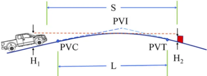
This input refers to the design value from the Hungarian guidelines for road design [7], which is corresponding with the design speed. This value was calculated depending on the human's capabilities and behavior, therefore in this study all other surrounding conditions assumed to be constant, sur- face road conditions and grade are assumed to remain the same, and the vehicle dynamic properties of autonomous vehicles and conventional vehicles are assumed to be iden- tical, thus, the braking distance is assumed to remain the same. Figure 1 illustrates the sight distance on the crest vertical curve, where L is the length of crest vertical curve (m); S is the sight distance (m); H1 height of eye above roadway surface (m); H2 is the height of object above roadway surface (m); PVI is the Point of Vertical Intersec- tion; PVC is the Point of Vertical Curvature; PVT is the Point of Vertical Tangency.
The distance traveled during Perception Reaction Time (PRT) is the product of the design speed of the vehicle and the PRT of the driver. According to UME [7], the human reaction time to full stop the vehicle before an obstacle is around 1 second divided into 0.7 second to detect the object and 0.3 second for the mechanical delay time of the hy- draulic brake system. There are some factors influencing the reaction distance:
Fig. 1.Sight distance on the crest vertical curve (Source: Author)
Vehicle speed;
Driver reaction time.
Factors reducing the reaction distance:
Hazard forecasting;
Preparedness, routine.
Factors that increase the reaction distance:
Alcohol, drug, or medication use;
Uncertainty in decision making;
Fatigue;
Distraction activities (e.g., telephone calls).
Factor influencing braking distance:
Vehicle speed
Quality and condition of the road;
Quality and condition of brakes;
Quality and condition of tires.
Anyway, human reaction time still difficult to give it a specific value due to the drivers vary in their responses to particular events and take longer to respond when decisions are complex, or events are unexpected. According to AASHTO the average of driver's reaction time is 0.6 seconds, with a few drivers taking as long as 2 s, consequently, for a simple, unexpected decision and action, some drivers may take as long as 2.7 seconds to respond. A complex decision with several alternatives may take several seconds longer than a simple decision [8]. Furthermore, the longer the re- action time, the greater the chance for error. The main difference between the human driver and autonomous vehicle is in the cycle of perceiving the situation, thinking about it and performing an action depending on the assessment, high-tech devices take over each of these tasks in case of AVs and the brain in case of a human driver.
On the other hand, AVs equipped with radar or LIDAR sensors and a camera system have a reaction time of 0.5 seconds. In terms of time, autonomous brake control is significantly superior to the other case because modern computers have a significantly higher speed than for a person to process and response to what they see.
4.2. Eye height
According to UME [7] for all sight distance calculations for passenger cars, the height of the driver's eye is considered to be 1.0 m above the road surface. The eye height in the AASHTO specifications is 1.08 m. In this analysis the human eye was set as 1.1 m rounding up the AASHTO value and following the global tendency of spreading of bigger vehicles e.g. SUV. The goal of this study was not the determination of the eye/sensor heights but a comparison of the sight distances of the different sensors and human eye. In case of autono- mous vehicles, this height depends on where each sensor is placed, thus, it differs from sensor to other.
4.3. Eye location
The difference between eye position in case of autonomous vehicle and human driven vehicle, in this study the eye
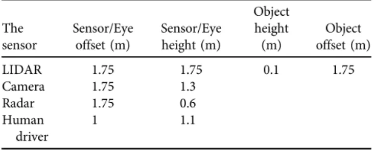
position of the autonomous vehicle is considered to be the position of LIDAR sensor, or camera, or radar. The offset of the eye and AV-sensors were defined as the lateral distance from the centerline of the road (Table 1).
4.4. Target (object) height
The object can be a human, or car, or animal, or stationary object (such as walls, fences, trees, poles, or bridges), etc.
According to AASHTO, for stopping sight distance and decision sight distance calculations, the height of the object is considered to be 0.60 m above the road surface (height of the rear lights of the car fore). For passing sight distance calculations, the height of the object is considered to be 1.08 m above the road surface [8]. Road model was created according to AASHTO, the object height however has been taken into account as 0.1 m according to the Hungarian guidelines (at a design speed of 90 km/h).
4.5. Target location
For this study the location of the object was examined in the middle of the vehicle's lane. All these parameters for the examined sensors are summarized inTable 1.
The crest vertical curve was examined three radii (3500 m, 5500 m, 7500 m) with design speed 90 km/h, lane width 3.5 m, grade in 2%, and grade out -2% (the evaluation of the effect of a wider range of grades is planned to be conducted in the next phase of the research project). Using check sight distance tool in AutoCAD Civil 3D with a check interval equals to 10 m representing as stations start from the beginning of the vertical curve and finish at the end of the vertical curve, and minimum sight distance which is corresponded to the design speed, from AASHTO, is 160 m.
The results for each radius were represented as case study as follows:
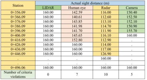
4.5.1. First case study R53500 m.Table 2 shows the resulted sight distances from AutoCAD Civil 3D and how many times every sensor violated the required minimum sight distance, the marked values refer to the obstruction points on the curve.
4.5.2. Second case study R55500 m. Results for R55500 m are shown inTable 3.
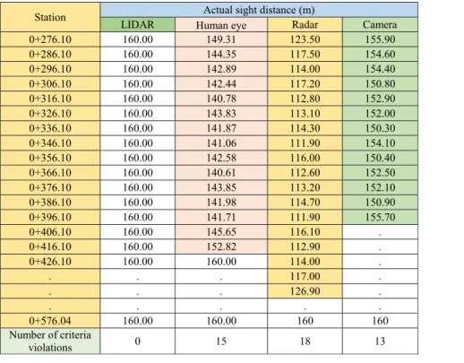
4.5.3. Third case study R57500 m. Results forR57500 m are shown inTable 4.
Table 1.The using parameters for every examined sensor
The sensor
Sensor/Eye offset (m)
Sensor/Eye height (m)
Object height (m)
Object offset (m)
LIDAR 1.75 1.75 0.1 1.75
Camera 1.75 1.3
Radar 1.75 0.6
Human driver
1 1.1
5. RESULTS DISCUSSION
From the previous tables, regardless of the range of each sensor and its capabilities, there is a clear disparity in the number of stations in which the required minimum sight distance is violated. In fact, this sight distance refers to the stopping sight distance because it is recommended that vertical curves be designed to provide at least the stopping sight distance, approval for speed design. This disparity is mainly due to the position of the sensor in the car, which in turn affects the sensor capabilities, based on the previ- ously mentioned results in terms of the number of viola- tions of design criteria, the sensors can be sequenced as follows:
LIDAR sensor, which is located on the top of the car;
Camera, which is located on the top of the windshield;
Human eye;
Radar front bumper integrated.
The position of the sensor, according to its height, may face more obstruction points the lower its height is, and this ex- plains why the radar has more obstruction points than the rest of the sensors, on the other hand, the LIDAR does not have any obstruction point. The presence of violations by the human element can be explained simply that the design is based on that the height of the target is 0.6 m. In fact, this height is not constant it may be larger or smaller, for this reason, these sensors were tested in case of an object with a height of 0.1 m, in addition to being affected by the speed of the car.
By taking the range of each sensor into consideration, all the examined sensors in general, with different techniques of operation, have a sufficient range to provide the minimum required sight distance and thus determine the position and Table 3.Sight distances for all the sensors which were examined at the radius 5500 m
Station Actual sight distance (m)
LIDAR Human eye Radar Camera
0+316.09 160.00 140.78 112.80 152.90
0+326.09 160.00 143.83 113.10 152.00
0+336.09 160.00 141.87 114.30 150.30
0+346.09 160.00 141.06 111.90 154.10
0+356.09 160.00 142.59 116.00 150.40
0+366.09 160.00 140.61 112.60 152.50
0+376.09 160.00 143.85 113.10 152.10
0+386.09 160.00 141.98 114.70 150.90
0+396.09 160.00 141.70 111.90 155.70
0+406.09 160.00 145.65 116.10 160.00
. . 152.80 112.90 .
. . . 114.00 .
. . . 117.00 .
. . . . .
0+536.05 160.00 160.00 160.00 160.00
Number of criteria
violations 0 11 13 9
Table 2.Sight distances for all the sensors, which were examined at the radius 3500 m
Station Actual sight distance (m)
LIDAR Human eye Radar Camera
0+356.09 160.00 142.59 116.00 150.40
0+366.09 160.00 140.61 112.60 152.50
0+376.09 160.00 143.85 113.10 152.10
0+386.09 160.00 141.98 114.70 150.90
0+396.09 160.00 141.70 111.90 155.70
0+406.09 160.00 145.65 116.10 160.00
0+416.09 160.00 152.80 112.90 .
0+426.09 160.00 160.00 114.00 .
0+436.09 160.00 160.00 117.00 .
0+446.09 160.00 160.00 126.90 .
. . . 160.00 .
. . . . .
0+496.06 160.00 160.00 160.00 160.00
Number of criteria
violations 0 7 10 5
height of the object. The height of the object and radius of the crest vertical curve can play an essential role in taking advantage of the sensors' capabilities, for example when the crest vertical curve has a small radius and high grade (grade in and grade out), therefore the length of the crest is small and the crest curve is sharp, in this case, the capabilities of the sensors will decrease but remain superior to the human driver who depends on what he mainly sees. In particular, the LIDAR sensor outperforms both the camera and the radar sensor because it is at a higher altitude than the rest of the sensors. Accordingly, the design speed can be increased, which reduces the time required to pass the crest in less time.
The position of the element on the road also has an essential role in affecting the capabilities of the sensors or even the human driver, especially since some sensors emit their waves or rays in a way that makes the process of identifying it slower and thus accidents occur.
The spread of AVs may affect the road design guidelines, the parameters however are expected to remain for a longer period of time because conventional vehicles may coexist with autonomous vehicles for decades. Speed regulation however may be different for autonomous vehicles because of the improved reaction times and advantageous combi- nation and location of the sensors.
6. CONCLUSION
Autonomous vehicles with their sensors can increase road safety. Hence, it is essential to study other design elements
and modify them if needed to be appropriate for AVs especially in the transitional period (mixed traffic of AVs and conventional vehicles) to achieve maximum advantages of their features.
These sensors with different types and capabilities should work together to increase road safety.
LIDAR sensor is a very promising technology therefore it should be studied to involve all the weather conditions such as: snow, rain, fog etc.
ACKNOWLEDGEMENT
The research presented in this paper was carried out as part of the“Dynamics and Control of Autonomous Vehicles meeting the Synergy Demands of Automated Transport Systems (EFOP-3.6.2-16-2017-00016)” project in the framework of the New Szechenyi Plan. The completion of this project is funded by the European Union and co-financed by the European Social Fund.
REFERENCES
[1] J. Khoury, K. Amine, and R. A. Saad,“An initial investigation of the effects of a fully automated vehicle fleet on geometric design,” J. Adv. Transp., vol. 2019, Paper no. 6126408, 2019.
[2] P. Intini, P. Colonna, N. Berloco, and V. Ranieri,“Rethinking the main road design concepts for future automated vehicles native roads,”Eur. Transp. - Trasp. Eur., vol. 73, no. 3, pp. 1–28, 2019.
Table 4.Sight distances for all the sensors, which were examined at the radius 7500 m
Station Actual sight distance (m)
LIDAR Human eye Radar Camera
0+276.10 160.00 149.31 123.50 155.90
0+286.10 160.00 144.35 117.50 154.60
0+296.10 160.00 142.89 114.00 154.40
0+306.10 160.00 142.44 117.20 150.80
0+316.10 160.00 140.78 112.80 152.90
0+326.10 160.00 143.83 113.10 152.00
0+336.10 160.00 141.87 114.30 150.30
0+346.10 160.00 141.06 111.90 154.10
0+356.10 160.00 142.58 116.00 150.40
0+366.10 160.00 140.61 112.60 152.50
0+376.10 160.00 143.85 113.20 152.10
0+386.10 160.00 141.98 114.70 150.90
0+396.10 160.00 141.71 111.90 155.70
0+406.10 160.00 145.65 116.10 .
0+416.10 160.00 152.82 112.90 .
0+426.10 160.00 160.00 114.00 .
. . . 117.00 .
. . . 126.90 .
. . . . .
0+576.04 160.00 160.00 160 160
Number of criteria
violations 0 15 18 13
[3] L. Oakes-Ash, J. Tricker, A. Dawn, and K. Allen, “Dedicated Driverless Spaces,” 2018. [Online]. Available: https://www.
cityscience.com/download/Dedicated-Driverless-Spaces.pdf.
Accessed: Sep. 20, 2020.
[4] Z. Magyari and C. Koren,“Impact of autonomous vehicles to vis- ibility requirements in road junction design,” in International Conference on Transport Science, Gy}or, Hungary, Szechenyi Istvan Egyetem, Mar. 21–22, 2019, 2019, pp. 1–6.
[5] A. Berenyi,“Laser scanning in engineering survey–An application study,”Pollack Period., vol. 5, no. 2, pp. 39–48, 2010.
[6]A. Somogyi, T. Lovas, and A. Barsi, “Comparison of spatial reconstruction software packages using DSLR images,” Pollack Period., vol. 12, no. 2, pp. 17–27, 2017.
[7] e-UT 03.01.11 road planning, Hungarian Road and Rail Society, 2008.
[8]A Policy on Geometric Design of Highways and Streets. 7th Ed.,American Association of State Highway and Transportation Officials, 2018.
Open Access. This is an open-access article distributed under the terms of the Creative Commons Attribution 4.0 International License (https://creativecommons.org/
licenses/by/4.0/), which permits unrestricted use, distribution, and reproduction in any medium, provided the original author and source are credited, a link to the CC License is provided, and changes–if any–are indicated. (SID_1)