GENERATING CONCEPTS WITH THE HELP OF GREEN TIPS
ÁGNES TAKÁCS
University of Miskolc, Institute of Machine and Product Design 3515, Miskolc-Egyetemváros
takacs.agnes@uni-miskolc.hu
Abstract:Conceptual design is the early phase of the whole design process where the designer engineer analyses the similar on the market existing products, complete them with his or her own ideas and generating new solutions this way. In a lucky situation the designer can generate all the possible solutions of the product. In this case analysing solutions is a really hard task and in many cases cannot be solved without the help of a computer. This paper introduces a previous work integrated by the tools of environmentally friendly design.
Keywords: design theory, methodology, Design for Environment
1. Introduction
Due to the literature of the field environmentally friendly design or DFE or Green design or eco design mean only the protection of the nature do not pay any attention to the protection of the human that is a component of the green environment, only indirectly referring to it. It is essential to notice that the man only as a designer but also as the part of the green environment appears in the machine-human-environment cycle. The elements of the cycle are interrelationship continuously. So the human designs for itself and for the environment as well. Machine has the effect for the human and for the environment too.
The environment also has the impact for the human and for the machine. So environment means not only the nature over the office, the factory, but the direct environment of the human where it works, so the workplace. As for the further researches it would be practical to mention and analyse ergonomics as the element of the environmentally friendly design.
2. Tools of DFE
2.1. DFE elements
Dfx, or design according to a given viewpoint [2] can be any formal period of the design process, or any important aspect that can be followed during the whole design activity as the main principle. Dfx is an enormous set of design principles that is really hard to describe, because this set is increasing day-by-day. Scientists define more and more principles, and for those principles methods are also created. These methods denote or can denote the adaption of Dfx techniques to computer. DFE, that is Design for the Environment is collecting the aspects of environmentally friendly design. It consists of seven essential areas: design for recycling, design to minimize material usage, design for disassembly, design for remanufacturing, design to minimize hazardous materials, design for energy efficiency, design to regulations and standards. According to different aspects these can be divided into other different principles. This figure also confirms why it is so complicated to collect all the Dfx techniques and to group them.
2.2. 3R, 4R, 6R
3R philosophy means nothing else but not accumulating used or consumed materials as waste, but recycling them to the product-market. Reduce means to lower the quantity of the waste, reuse means using again the waste, recycling means using waste for creating new raw material. There are several versions for 4R. Usually recover, rethink and replace are mentioned as the 4th R.
Elements of 6R are recycle, reuse, repair, replace, reduce, rethink. Rethinking a product can lead to an absolute green product, for instance using biodegradable materials. Of course it determines and might lower the life-time of the product (e.g.: plant-a-tree box, as a packaging carton box, patent no.: US20080046277A1). But this way the effect on the environment can be reduced the most. Reducing the waste cannot be the best solution, as even though making the quantity of the waste less, it still has the impact on the environment. During redesign certain assemblies can be changed by less harmful ones.
Repairing a product that is out of order its lifetime gets longer, so less new product is needed. It is sure that this possibility is not proper for the manufacturers. Reusing a product is significant for the environment. Due to recycling less natural raw materials have to be extracted. The recycled raw material has no impact on the environment as waste, but the recycling procedure might be dangerous for the environment. It does not mean to be worst than extracting the natural materials.
2.3. Valdez or CERES principles
There are several principles that were defined to make the industry understand and deal with the effects of producing for the environment. For example Valdez principles that were published in the Financial Times 27th March 1991. These principles later had been renamed for CERES principles. Coalition for Environmentally Responsible Economies had been established by Joan Bavaria in 1989 that is the abbreviation for CERES, who was the Roman goddess for fertility and agriculture. After the Exxon Valdez oil spill in the same year of establishing, CERES determined its 10 point principles. These help factories producing with the highest environmentally efficiency. Many industries keep CERES principles in front of the eye nowadays, General Motors among others.
2.4. Ten Golden Rules
Ten golden rules were carried out by Luttropp and Lagerstedt [1]. The rules are the summary of those principles that are used by different industries, and suggested by hand books. Ten golden rules are quite general; each industry should carry out product and industry specific rules.
2.5. Life cycle assessment
Figure 1 shows the stages of the product lifecycle in the point of view of the material.
The process starts with the extraction of the raw material, with that the production of the stock can be started. From the stock products are prepared. These products become wastage after using them. Waste can be reused in several ways. By reusing those elements of products that have longer life, than other parts, products can be fixed (for instance scrap yards). In case of remanufacturing elements of the product are in the production line again (Remy Automotive). During the recycling process new materials are produced from the used ones (gathering PET bottles).
Figure 1. Product-material-lifecycle [2]
Aim and object
Stocking
Effect analysis
Interpretation
Figure 2. Frame-system of the LCA
Life cycle assessment deals with the possible impacts on the environment a product can cause during its whole life according to the Figure 1 [4]. According to ISO 14040 the frame-system of LCA is shown in Figure 2. To take a stock (or strike a balance) is the stage of LCA, where the material and energy consumption and emission of the analysed system during the whole lifecycle or a stage of it is listed. This stage of the LCA is the process where energy and raw material necessity is objectively determined on the basis of data.
Over this stocking stage includes the definitions of water and air emissions, waste, and other environmentally emissions through the lifecycle of a product, process or service.
Effect analysis is the stage of LCA that has the aim to explore and evaluate how big and significant the environmental effect of the analysed system. During this stage of LCA environmental effects listed in the stocking stage are evaluated. Stocking data should be assigned to effect categories, classified and characterised. As a result each environmental category has a value as the effect of the analysed lifecycle.
3. Ergonomics
MacLeod [5, 6] defined twelve principles that can help the designer’s work during the design process to create a machine, tool, equipment or product that ensures comfortable work for the user. These principles are general, but give significant help during design.
David Ridyard determined five main territories within he declared several design principles for neutral postures. The aim is to ensure these normal positions.
Raw material extraction
Production of the stock
Product production
Using the product
Waste management
4. Conceptual design
Design task
Definition of customer’s requirements Market- and patent analysis
Ranking customer’s requirements Finding and defining functional subassemblies functional subassembly-
importance
Definition of construction requirements
Ranking of construction requirements
Finding and defining connections among functional subassemblies connection-
importance
Defining evaluating aspects according to the construction’s requirements
Ranking evaluating aspects
Generating the solution variants
Choosing the optimal solution variant
Quality line Quantity line
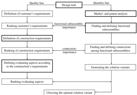
Figure 3. Conceptual design process – a suggestion
Figure 3 [7] focuses on the main scope of researches; it summarises the phase of the conceptual design. Suggested method introduced by Figure 3 implies a relatively simple algorithm, so the process is adaptable for computer. The introduced method consists of a quantity and a quality line. Quantity line makes it possible the designer could pay attention on more aspects, so more functional subassemblies and this way more solutions. Quality line valuates solutions according to different view-points and tightens the solution-space, optionally for one proper solution. In the modern World of our days it significantly facilitates the task of the engineering designer.
As it is shown in Figure 3 certain steps of the conceptual design process are indicated by thick line. These are the steps where the creativity of the designer appears and the designer has to pay attention to the given circumstances, rules, laws and in these steps the tools of the DFE can also be taken into consideration. Right now, on this stage of the research it cannot be defined by numbers how effective it is. Quantification would be easier if a catalogue have been composed that would collect those functional subassemblies that have some kind of ‘green’ effect, and take one of the DFE tool as a basis.
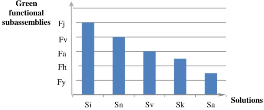
Green functional subassemblies have to be determined in a separate group to take into account the expectable effects on the environment with the help of an existing software operating on the basis of the process introduced in Figure 4. For example solar battery different types of filters, led lightning can be green functional subassembly. These should be ranked on the basis of their expectable effect on the environment, but designers’ claims also have to be kept in front of the eye. According to the importance order of green functional subassemblies a diagram can be composed that ranks the promising solutions
due to the number of green functional subassemblies can be found in them. So diagram in Figure 4 arises.
Figure 4. Ranking solutions on the basis of green functional subassemblies
Diagram shows, which preliminary determined and ranked green functional subassemblies are chosen to compose the different solutions. So solution i (Si) contains all the green functional subassemblies signed in diagram (Fy, Fh, Fa, Fv, Fj) among them the strongest one that has the highest environmental effect is functional subassembly j, while the weakest one is functional subassembly y that has the less effect on the environment.
This weakness means that the given functional subassembly assists the less the environmentally friendly design. So solution Si is the most environmentally friendly according to Figure 4.
5. Green Tips
Previously collected environmentally friendly tools are suggesting very general possibilities for designers. It would be really hard to get them one-in-one in the conceptual design phase, this very early phase of the whole design process. So on the basis of the introduced principles a system should be carried out that are can be adapted even in this early phase of design and effectively assist the designers’ work. In this phase designers still do not know sizes, materials, maybe certain connections can be determined, but no constructional features are available, because this task is realised in a later phase of the design. Expectable green effects can also be evaluated later. But certain principles can be taken into consideration.
HT1 HT2 HT3 … HTn
GT1 GT2 GT3
… GTn
Figure 5. Tip matrix
Si Sn Sv Sk Sa
Green functional subassemblies
Solutions Fj
Fv Fa Fh Fy
Figure 5 introduces Tip Matrix. The first column of the matrix contains the green tips (GT) and the first row human tips (HT) that are in connection with ergonomics. In the cells of the matrix those functional subassemblies can be found that are possible solutions not only from the point of view of green tips, but from the point of view of ergonomics as well.
Of course a functional subassembly kit also should be previously composed.
6. Summary
On the basis of the above introduced principles defining a list is in process that takes not only environmentally friendly design but ergonomics as well into consideration. And on this basis gives suggestions to the designer during the conceptual design phase while making the list of functional subassemblies by suggesting ones from the built-in ones.
Further task is to develop the subassembly-kit and the tip-list.
7. Acknowledgement
This research was supported by the European Union and the State of Hungary, co-financed by the European Social Fund in the framework of TÁMOP-4.2.4.A/2-11/1-2012-0001 ‘National Excellence Program’.
8. References
[1]Luttropp, C.–Lagerstedt, J.: EcoDesign and The Ten Golden Rules: generic advice for merging environmental aspects into product development. Journal of Cleaner Production, 2006.
[2]Otto, K.–Wood, K.: Product Design – Techniques in Reverse Engineering and New Product Development. Prentice Hall, 2008.
[3]Pahl, G.–Beitz, W.: Engineering Design – A Systematic Approach. Springer Verlag, London, 2005.
[4]Tóthné Szita, K.: Életciklus-elemzés, életciklus hatásértékelés. Miskolci Egyetemi Kiadó, Miskolc, 2008.
[5]MacLeod, D.: The Ergonomics Kit for General Industry. ISBN 1280546115, ebook, CRC Press, 2006.
[6]MacLeod, D.: The Rules of Work – A Practical Engineering Guide to Ergonomics. ISBN 1560328851, ebook, CRC Press, 2000.
[7]Takács, Á: Számítógéppel segített koncepcionális tervezési módszer. PhD-disszertáció, Miskolc, 2010.
[9]Sarka, F.–Döbröczöni, Á.: Analysis of gear drives and searching of noise reduction possibilities with the help of graphs. Design of Machines and Structures, Vol. 4, No. 1, Miskolc, 2014.
[10]Patkó, Gy.–Takács, Gy.–Demeter, P.–Barna, B.–Hegedűs, Gy.–Barak, A.–Simon, G.–Szilágyi, A.: A process for establishing the remanent lifetime of rolling element bearings. XXIV. microCAD International Scientific Conference, Miskolc, March 2010.
Á. DÖBRÖCZÖNI Institute of Machine- and Product Design University of Miskolc
H-3515 Miskolc-Egyetemváros, Hungary machda@uni-miskolc.hu
M. GERGELY Acceleration Bt.
mihaly_gergely@freemail.hu
K. JÁRMAI Department of Materials Handling and Logistics University of Miskolc
H-3515 Miskolc-Egyetemváros, Hungary altjar@uni-miskolc.hu
I. KEREKES Institute of Mechanics
University of Miskolc,
H-3515 Miskolc-Egyetemváros, Hungary mechker@uni-miskolc.hu
F. J. SZABÓ Institute of Machine- and Product Design University of Miskolc
H-3515 Miskolc-Egyetemváros, Hungary machszf@uni-miskolc.hu
A. SZILÁGYI Institute of Machine Tools and Mechatronics University of Miskolc
H-3515 Miskolc-Egyetemváros, Hungary szilagyi.attila@uni-miskolc.hu
J. PÉTER Institute of Machine and Product Design
University of Miskolc
H-3515 Miskolc-Egyetemváros, Hungary machpj@uni-miskolc.hu
![Figure 1. Product-material-lifecycle [2] Aim and object Stocking Effect analysis Interpretation](https://thumb-eu.123doks.com/thumbv2/9dokorg/1127297.79700/3.892.177.713.201.606/figure-product-material-lifecycle-stocking-effect-analysis-interpretation.webp)