Performance Guarantees on Machine-Learning-based Overtaking Strategies for Autonomous Vehicles
Bal´azs N´emeth, Tam´as Heged˝us and P´eter G´asp´ar
Abstract— The control of autonomous vehicles in overtaking scenarios is an important challenge, in which an autonomous vehicle in a multiple vehicle environment must be safely driven.
Due to the complexity of vehicle scenarios, several machine- learning-based design strategies have been developed, which provide outstanding results. However, in most of these methods it is difficult to provide a theoretical guarantee on the most important performance of the overtaking strategy, i.e., the avoidance of collisions with the surrounding vehicles. This pa- per proposes a design architecture with which this performance can be guaranteed. The method is based on the robust control framework and it is independent from the structure of the machine-learning-based agent. The effectiveness of the method is illustrated through simulation examples.
I. INTRODUCTION AND MOTIVATION
Machine-learning techniques are important components in the control of automated and autonomous vehicle sys- tems. The advantage of the learning methods is that several decision processes, perceptions and the characteristics of human driving interventions can be effectively integrated in their agents. Machine-learning techniques have a special importance at the handling of the complex multi-vehicle scenarios.
Although there exist several optimal control solutions to the problem of overtaking maneuvers [1], [2], [3], [4], machine-learning-based methods have also been successfully applied. A reinforcement-learning-based overtaking control strategy is proposed in [5], [6]. In [7] a Q-learning strategy is used in the design of driving algorithms for multi-lane environments. An analysis method of the robust properties of the machine-learning-based overtaking decision strategies is found in [7]. A deep-reinforcement-learning method is used in [8], which is applied to decision making in different manoeuvres. The applied method provides the possibility of behaviour adaptation without re-training and thus, the agent is capable of adhering to traffic rules and learns to drive safely in a variety of situations.
In spite of the promising results on the application of machine learning methods in the overtaking control strate-
B. N´emeth, T. Heged˝us and P. G´asp´ar are with Systems and Control Laboratory, Institute for Computer Science and Control, Kende u. 13-17, H-1111 Budapest, Hungary. E-mail:
[balazs.nemeth;tamas.hegedus;peter.gaspar]@sztaki.hu
This work has been supported by the GINOP-2.3.2-15-2016-00002 grant of the Ministry of National Economy of Hungary and by the European Commission through the H2020 project EPIC under grant No. 739592. The work of Bal´azs N´emeth was partially supported by the J´anos Bolyai Re- search Scholarship of the Hungarian Academy of Sciences and the ´UNKP- 19-4 New National Excellence Program of the Ministry for Innovation and Technology. The work of Tam´as Heged˝us was partially supported by the ´UNKP-19-3 New National Excellence Program of the Ministry for Innovation and Technology.
gies, a crucial problem is the lack of performance guar- antees, see [9]. A current issue is how it is possible to quantify and guarantee performance levels of a machine- learning-based agent in the sense of the control theory.
The challenge is that the mathematical structure of the machine-learning-based algorithms and the formulation of the dynamic control systems are different. This complexity makes it difficult to examine the system which is yielded via their interconnections. Moreover, the conventional control systems are generally designed based on simplified control- oriented models, which are also used in the evaluation of closed-loop stability and performances [10]. It means that the machine-learning-based control systems can be complex for the evaluation of the closed-loop system through the conventional analysis methods. Although there are some novel results in the research on guarantees, e.g. [11], [12], the problem is still open.
This paper focuses on trajectory design and control design methods for machine-learning-based overtaking strategies with which the performance of collision avoidance can be guaranteed. The motivation of the paper is to provide a design framework, which is able to provide the advantages of a machine-learning agent (e.g. self-learning, achievement of human expectations through samples), while its drawback about the lack of performance guarantee is eliminated. As a novelty of the method, the generated trajectory of the machine-learning method is verified using a guaranteed safe trajectory, which is computed through an optimization task.
Formally, it results in a measured disturbance, which is incorporated in the robust design of the local trajectory track- ing control. The effectiveness of the method is illustrated through simulations using CarMaker. It is illustrated that the emergency, which results from an unexpected event for the machine learning algorithm, can be avoided.
The paper is organized as follows. The machine-learning- based trajectory design is presented in Section II. The design method of the guaranteed safety trajectory is formed in Section III. Section IV proposes the LPV-based control design, which guarantees the minimum performance level of the system. Simulation results are shown in Section V and the contributions are summarized in Section VI.
II. MACHINE-LEARNING-BASED TRAJECTORY DESIGN
In this section a machine-learning-based trajectory design algorithm for the overtaking problem is presented. The design of the agent has three stages.
1./ The training set of the supervised learning method is generated. It requires an off-line method, in which the 2020 European Control Conference (ECC)
May 12-15, 2020. Saint Petersburg, Russia
route and the acceleration outputs for various scenarios are computed. The method is based on the results of [13], [14].
In this solution a graph-based algorithm is applied, in which several factors can be incorporated, e.g. a probability map of the surrounding vehicle positions, the comfort in the route selection, the decision of the overtaking, etc. Although the graph-based optimization provides an acceptable route for the vehicle, the numerical complexity makes it difficult in an online implementation. Thus, optimization can be used only as an off-line process. The motivation of the learning is to ignore the necessity of the online solution of the graph-based optimization problem. Therefore, in the proposed solution the optimization is performed for numerous scenarios and their results are used as a training set.
2./The generated training set must be processed by a su- pervised learning method, which results in a neural network.
The training is also an off-line process, but the resulting neural network can be used in an on-line process.
3./ During the cruising of an autonomous vehicle several multi-vehicle scenarios must be handled. The scenarios can be used to enlarge the training set. This requires the logging of the input data and an off-line solution of the graph-based optimization. If the training set is enlarged, the initial neural network based on the enlarged set can be retrained. Using this self-learning process the trajectory design method for the autonomous vehicle can be improved, which is an advantage of the method. Unfortunately, the self-learning capability has the drawback that the future structure and the numerical values of the neural network may be unknown.
In the rest of this section the training process of the neural network is briefly presented.
Training of the machine learning agent
The neural network is a member of the machine learning family. The artificial neural network is modeled after the human brain in such a manner that it is able to solve complex, nonlinear problems. The main advantage which distinguishes this technique from the conventional machine learning algorithms is its ability to deal with different kinds of optimization tasks, such as clustering, classification, pre- diction, fitting etc. A neural network contains weights and activation functions, which are called neurons. They are grouped into layers. A network has one input and one output layer and, at least, one hidden layer. The number of the hidden layers and the type of the activation function can be chosen freely, and they are the main parameters of the neural network [15].
In this paper the neural network is trained using a su- pervised learning technique, which requires a data set for training and testing purposes. The training set is a subset of the collected data set, which is used for training the network.
Another subset is the test set, which is used for evaluating the neural network. The data set is generated through 5000 dis- tinct scenarios, in which the proposed graph search algorithm has been performed. During the data collection the initial parameters of the scenarios are selected randomly, e.g., the positions or the velocity values of the vehicles. The results of
the graph-based decision-making algorithm are the computed trajectory and the velocity profile. For the reduction of the computation in the training, the resulting lateral position values are transformed into discrete values0;±1. The value means that the lateral position is not modified concerning the previous computation. ±1 represents that the trajectory is modified to one step right or left on the grid. In the computation of the trajectory the road horizon is divided into 10 steps in longitudinal, and 7 in lateral directions, which results in a grid with 70 points.
The structure of the network consists of one input, one output and 3 hidden layers. The hidden layers contain 8−10−12neurons. The numbers of the hidden layers and the neurons are selected by using the so-called k-fold cross validation technique [16]. The input vector of the network on the input layer contains
• the velocity difference between the actual velocity of the vehicle and the current velocity regulations,
• the lateral position of the vehicle,
• the distances and the velocity differences between the controlled vehicle and the further vehicles in the over- taking scenario.
The results of the neural network are the trajectory in grid step representation and the velocity profile vx,i+1,l. The trajectory is converted into position values using a further smoothing layer, which results inyi+1,l.
A further crucial part of the network is the used activation functions. Although there exist numerous functions that can be used in the training process, the rectified linear unit (ReLU) and the log-sigmoid functions are used in this estimation problem, because they can be easily adjusted to nonlinear problems. For training the network, the Levenberg- Marquardt algorithm is used [17].
III. FORMULATION OF SAFE REFERENCE TRAJECTORY
The generation of a safe trajectory for overtaking is de- signed through a predictive optimization strategy [18], whose minimum performance level is quantified. The following description provides a brief overview of the mehtod. In the trajectory design problem the lateral motion of the vehicle is formulated based on the kinematic model of the vehicle and the trajectory of the vehicle is formed as clothoid segments [19].
The curvature of the clothoid is a continuous function, which means that the relation between the curve in section i and i+ 1 is κi+1 =κi+ciLi, where Li is the distance between two section points andciis the ratio of the clothoid section. Moreover, during the cruising of the vehicle the velocity vx,i may vary with constant acceleration a, which leads to the relation vx,i+1 = vx,i + aT, where T is sampling time. The kinematic motion equations using the representation of the curvature and the velocity profile is transformed into a state-space representation
xi+1=A(a)xi+B(a)ci, (1)
wherexi=
yi ψi κiT
is the state vector of the system andciis its input andA(a), B(a)are acceleration-dependent matrices.
The goal of the design is to provide a trajectory which guarantees the avoidance of the objects on the road with min- imum lateral displacement. The objective of the optimization is to minimize |yi|for all i= 1. . . n, which represents the prediction horizon. The criterion is formed in an objective function
J(C) = 1
2YT(C)QY(C) +CTRC, (2) whereY contains the predicted lateral errors,C involves the clothoid ratios,QandR are weighting matrices.
During the optimization the actual positions of the objects and the borders of the lanes must be considered. The posi- tions are incorporated in constraint relations on yi+j, ∀j ∈ {1, n−1}. The role of the constraints is to limit the minimum and the maximum lateral values of the designed trajectory, such asyi+j≥yi+jmin,yi+j ≤ymaxi+j ,∀j∈ {1, n−1}. where
yi+jmin=yi+jmin,o+d, (3a) ymaxi+j =yi+jmax,o−d. (3b) In the computation of yi+jmin, ymaxi+j two components are involved.ymin,oi+j andymax,oi+j are determined by the positions of the objects and the borders of the lane.dis safe distance, which has an important role in the performance specification of the trajectory design algorithm. drepresents the smallest distance between the safe trajectory and the objects or the borders of the lane. It has impact on the guaranteed minimum performance level of the vehicle control system.
The trajectory design leads to a constrained optimiza- tion problem, in which the objective function (2) must be minimized subject to the constraints on yi+1. During the optimization the constrained optimization is solved for various fixedaacceleration values and the minimum ofJ(C) is requested depending on C, a. The variables in C and the parameteraare also bounded by constraint. The optimization leads to a series of clothoid ratios on the horizon from which the safe trajectory yi+1,s, vx,i+1,s in the next step i+ 1 is computed.
IV. ROBUST CONTROL DESIGN OF THE AUTONOMOUS OVERTAKING STRATEGY
In this section the tracking control design method is proposed. The goal of the control is to perform the overtaking maneuver without a collision. It contains two tasks:
• it is necessary to decide about the acceptability of the machine-learning-based reference signal,
• the reference signal must be tracked with a limited error, with which a predefined safe distancesfrom the objects is guaranteed.
In the following the solutions of these tasks are presented.
A. Examinations on the reference signals
The reference signals for the vehicle control are the designed trajectoryyref and the desired longitudinal velocity vref. In the generation of these signals yi+1,l, vx,i+1,l and yi+1,s, vx,i+1,s are considered.
The calculation of yref and vref are based on the rela- tionships
yref =yi+1,s+ ∆∗l,1, if ∆∗l,1∈Λl,1, (4a) vref =vx,i+1,s+ ∆∗l,2, if ∆∗l,2∈Λl,2, (4b) where∆∗l,1,∆∗l,2 are scalar design parameters andΛl,1,Λl,2
are domains.
The values of∆∗l,1,∆∗l,2are selected in such a way that if the conditions of (4) are guaranteed, thenyref =yi+1,l and vref =vx,i+1,l, such as
∆∗l,1=yi+1,l−yi+1,s, (5a)
∆∗l,2=vx,i+1,l−vx,i+1,s. (5b) But, if the conditions of each relation are not guaranteed in (4), then the design parameters are limited with the boundaries of their domains. It means that the general rule of the reference signal formulation is
yref =yi+1,s+ ∆l,1, (6a)
vref =vx,i+1,s+ ∆l,2, (6b) where
∆l,1= min max(∆∗l,1; ∆l,1,max); ∆l,1,min
, (7a)
∆l,2= min max(∆∗l,2; ∆l,2,max); ∆l,2,min
, (7b) where∆l,1,min,∆l,1,max,∆l,2,min,∆l,2,maxare the bound- aries ofΛl,1,Λl,2.
The formulations (6)-(7) show that yref, vref must be inside of a limited neighbourhood of the safe trajec- tory yi+1,s, vx,i+1,s. In practice, it is suggested to select
|∆l,i,max| = |∆l,i,min| = ∆l,i,m, i = {1; 2}, which leads to symmetric domains. If the domains are small, then the machine learning based trajectory is often overridden, with which the benefits of the learning can be degraded.
But, if the domains are broad, then an incorrect reference signal yi+1,l, vx,i+1,l is not improved in time. Thus, it is recommended to select the initial value ofΛl,1,Λl,2 bound- aries through test experiences on the trajectory generation algorithms, e.g. simulations or real experiments. Moreover, there are further conditions, which must be considered during the selection, as it is proposed below.
The selection of Λl,1 has high importance on the guar- anteed minimum performance level of the entire overtaking control system, because the distance between the safe refer- ence trajectoryyi+1,s and the object or the lane border can decrease through ∆l,i,m. The minimum performance level of the system is influenced byd(see (3)),∆l,i,m andey, ev
tracking errors ofyref,vref.
The performance specification of the overtaking control is defined that the minimum distance between the controlled vehicle or the lane border isssaf e. In a worst case scenario
the following constraint must be guaranteed, see an illustra- tion in Figure 1:
d−∆l,1,m−ey−ey,v−H/2≥ssaf e, (8) where the components are the following. The value d is selected in the design of the safe reference trajectory. The value ∆l,1,m is selected and built in the control design through the scaling of the reference signal. The value of ey is built in the control design directly through the scaling of the control performances. Sincevx,influences the lateral motion of the vehicle, ev can cause a lateral position error ey,v. It is computed through kinematic relations as
yi+1=yi+T vx,i+vref −vx,i
2 T+evT 2 =
=yi+1,s+ey,v, (9)
whereey,v=ev2T. The valueevis built in the control design directly through the scaling of the control performances, which leads to ey,v. Moreover, the value H represents the width of the vehicle.
ssaf e d
∆l,i,m
∆l,i,m
safe trajectory learning trajectory
bound
bound
ey+ey,v realized trajectory
H
Fig. 1. Illustration of the overtaking trajectories
The inequality (8) shows that there are several parameters which must be selected during the design. In practice, it is recommended to select d and ∆l,i,m at high values, while ey andev must be selected at a small value in the design.
B. Design process of the robust controller
The design of the tracking control requires the model of the vehicle, which is described through the following dynamical model [20]:
m¨y=Cf
δ−ψl˙ f+ ˙y vx
+Cr
ψl˙ r−y˙ vx
, (10a)
Jψ¨=Cflf
δ−ψl˙ f+ ˙y vx
−Crlr
ψl˙ r−y˙ vx
, (10b)
mv˙x=Flong−Fdist (10c)
whereJ is the yaw inertia of the vehicle,m is the vehicle mass, Cf, Cr are the cornering stiffness coefficients and lf, lr are geometric parameters. The signal y˙ is the lateral velocity and ψ˙ is the yaw rate. The longitudinal dynamics is described byvx and the longitudinal traction force Flong
and the disturbances Fdist, e.g. rolling resistance, air drag etc.
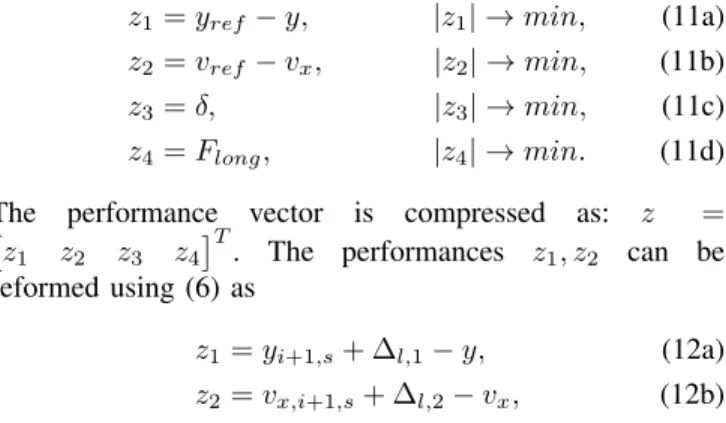
The designed controlled system must perform the follow- ing control performances
z1=yref−y, |z1| →min, (11a) z2=vref −vx, |z2| →min, (11b)
z3=δ, |z3| →min, (11c)
z4=Flong, |z4| →min. (11d) The performance vector is compressed as: z = z1 z2 z3 z4T
. The performances z1, z2 can be reformed using (6) as
z1=yi+1,s+ ∆l,1−y, (12a)
z2=vx,i+1,s+ ∆l,2−vx, (12b) in which yi+1,s, vx,i+1,s and ∆l,1,∆l,2 are measured dis- turbances. There is an important difference between these signals
• yi+1,s, vx,i+1,s are generated by the safe trajectory design method. Their characteristics (i.e. bounds, rates) are determined by the optimization algorithm.
• ∆l,1,∆l,2 are the result of various signals, such as the machine learning algorithm, the safe trajectory design algorithm and the selected values∆l,1,m,∆l,2,m. Since the sources of disturbances are different it is recom- mended to handle them separately.
The measured signals of the systems are the tracking errors
ym,1=yref −y, (13a)
ym,2=vref−vx, (13b) where ym =
ym,1 ym,2T
vector contains the measured signals.
The dynamic equations (10), the performance (11)-(12) and the measurement equations (13) are transformed into a LPV state-space representation
˙
x=A(ρ)x+B1w+B2u, (14a) z=C1x+D11w+D12u, (14b)
ym=C2x+D21w (14c)
whereA(ρ), B1, B2andC1, C2, D11, D12, D21are matrices.
x =
˙
y ψ˙ vx
T
is the state vector, the disturbance is w =
Fdist yi+1,s vx,i+1,s ∆l,1 ∆l,2T
and the control input vector isu=
δ FlongT
.ρ=vx is selected as a scheduling variable of the LPV system.
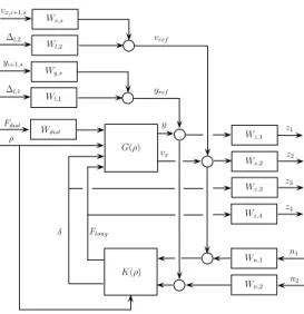
The control design is based on a weighting strategy, which is formulated through the closed-loop interconnec- tion structure, see Figure 2. The interconnection structure contains several weighting functions, whose roles are to guarantee the trade-off between the performances and to scale the signals. The weightsWn,1, Wn,2 are related to the sensor characteristics on the lateral and the velocity error measurements, where n1, n2 represent noises. Wdist scales the longitudinal disturbance force.
G(ρ)
K(ρ)
Wz,1 Wz,2
Wz,3 Wz,4
Wn,1
Wn,2 Wl,1
Wdist z1
z2 z3
z4
n1
n2
Fdist
∆l,1
ρ
Flong
δ
vx y Wy,s
yi+1,s Wl,2 Wv,s
∆l,2
vx,i+1,s
vref
yref
Fig. 2. Closed-loop interconnection structure
The role of weightsWy,s, Wv,sis to consider the dynamics of the reference signalsyi+1,s, vx,i+1,s. Similarly,Wl,1, Wl,2
scale the disturbances∆l,1,∆l,2. The weights are selected as Wl,1= ∆l,1,m
T12s2+T11s+ 1, Wl,2= ∆l,2,m
T22s2+T21s+ 1, (15) where Ti,j are design parameters, which represent the dy- namics of the signal. ∆l,i,m are selected based on (8). The selected forms guarantee that the values of the disturbances are∆l,1,m,∆l,2,m in steady state.
Wz,1, Wz,2andWz,3, Wz,4are the weights for the perfor- mances, which represent the minimization of them. Weights Wz,1, Wz,2have important role from the aspect of the overall performance of the overtaking control, because they scale the tracking errorsey, ev (8). The forms of the weights are
Wz,1= ey
T10s+ 1, Wz,2= ev
T20s+ 1, (16) where T10, T20 are design parameters and ey, ev are the expected tracking errors. The selected forms guarantee that the tracking errors areey, ev in steady state.
The design of the control is based on robust LPV method [21]. The problem is set up by gridding the parameter space and solving the set of LMIs that hold on the subset of FP. The induced L2 norm of parameter-dependent stable LPV systems with zero initial conditions is defined as
infK sup
%∈FP
sup
kwk26=0,w∈L2
kzk2
kwk2. (17) The result of the optimization are the LPV controller Kρ, which which steering angle δ and the longitudinal force Flong are computed.
Finally, Figure 3 shows the architecture of the entire control system, which is incorporated in the robust LPV controller and the generation blocks of the learning and safe reference signals. The role of the measured disturbance generator is to perform the computations (5)-(7).
Vehicle
robust LPV controller
safe trajectory generation machine learning
algorithm measured
generator
road&trafficenvironment
yi+1,l vx,i+1,l yi+1,s vx,i+1,s
∆l,1
∆l,2 δ
Flong
measured vehicle signals
road & traffic information disturbance
Fig. 3. Architecture of the entire control system
V. SIMULATION RESULTS
The effectiveness of the proposed method is illustrated through simulation examples, in which the CarMaker vehicle dynamic software is used. In the scenario the machine- learning-based algorithm designs a trajectory of the vehicle, which is not safe enough and the vehicle may lease the road.
This results in a scenario, which has been rare in the training set and thus, the machine-learning-based algorithm has a low performance. Nevertheless, the proposed robust control algorithm is able to guarantee the safety of the vehicle owing to the modification of the trajectory.
In the example the performance is guaranteed based on the inequality (8). The required safe distance is ssaf e= 0.5m.
The width of the vehicle isH = 2m. In the design of the LPV control ey = 0.005m and ev = 0.05m/s tracking errors are selected. Since T = 0.05s sampling time is selected, the lateral error from the velocity tracking error is ey,v = evT /2 = 0.05 = 0.00125m. It means that the selection of d = 2.1m and ∆l,1,m = 0.5m guarantees the required performance, such as
2.1m−0.5m−0.005m−0.00125m−1m=
= 0.59375m≥0.5m.
The trajectory and velocity profile results are presented in Figure 4. They show that the motion of the vehicle is smooth and the maximum velocity regulation is kept through the tracking of the safe velocity profile generation.
0 50 100 150 200 250
−0.5 0 0.5 1 1.5 2 2.5 3 3.5
Longitudinal position (m)
Lateral position (m)
(a) Lateral position
0 5 10 15
13 14 15 16 17 18 19 20
Time (s)
Veloctiy (m/s)
vx,i+1,l vx,i+1,s Real velocity
(b) Velocity signals Fig. 4. Motion of the vehicle
Figure 5 compares results of the learning and the safe trajectories at three periods of the overtaking manoeuvre. The results show thatyi+1,lcan lead to the departure of the road, which is avoided through the proposed method. Moreover, in the second segment the safe distance between the vehicles is preserved, see after8.8s. As a result, the reference trajectory is inside of the safe trajectory during the entire scenario. It guarantees the most important performance of the overtaking strategy.
8 8.5 9 9.5 Time (s)
2.6 2.8 3 3.2 3.4
Lateral position (m)
Safe Learning Reference Real
11 11.5 12 12.5
Time (s) -2
-1 0 1 2 3
Lateral position (m)
Safe Learning Reference Real
4 4.5 5 5.5
Time (s) 0
1 2 3 4
Lateral position (m)
Safe Learning Reference Real
Fig. 5. Trajectories of the vehicle in various segments of the road
Finally, the control inputs of the system are illustrated in Figure 6, which are actuated on the vehicle. Through the steering angle (Figure 6(a)) and Flong (Figure 6(b)) the tracking of the reference trajectory (Figure 5) and the velocity (Figure 4(b)) are successfully performed.
0 5 10 15
Times (s) -0.025
-0.02 -0.015 -0.01 -0.005 0 0.005 0.01 0.015 0.02 0.025
Steering angle (rad)
(a) Steering angleδ
0 5 10 15
Time (s) 0
500 1000 1500 2000 2500 3000 3500
Force (N)
(b) Longitudinal forceFlong
Fig. 6. Control interventions
VI. CONCLUSIONS
The paper has proposed a design architecture for machine- learning-based trajectory design methods, with which the avoidance of collisions with the surrounding vehicles during the overtaking strategy can be guaranteed. During the simu- lation examples the effectiveness of the method is illustrated as follows. The proposed neural-network-based trajectory design method has been able to provide an appropriate trajec- tory. However, it has also been presented that in some special scenarios the generated trajectory may cause hazardous sit- uations. Using the proposed robust design framework it has been possible to avoid these situations: the trajectory has been limited to vary in a neighbourhood of a safe trajectory.
The neighbourhood has been represented by the domain of a known disturbance, which has been incorporated in the robust control framework. The result of the paper has been a control design method which satisfies the safety requirements of overtaking manoeuvres.
REFERENCES
[1] K. Berntorp, “Path planning and integrated collision avoidance for autonomous vehicles,” inAmerican Control Conference, Seattle, 2017, pp. 4023–4028.
[2] N. Murgovski and J. Sj¨oberg, “Predictive cruise control with au- tonomous overtaking,” in 2015 54th IEEE Conference on Decision and Control (CDC), Dec 2015, pp. 644–649.
[3] N. A. Nguyen, D. Moser, P. Schrangl, L. del Re, and S. Jones,
“Autonomous overtaking using stochastic model predictive control,”
in2017 11th Asian Control Conf. (ASCC), Dec 2017, pp. 1005–1010.
[4] P. Petrov and F. Nashashibi, “Modeling and nonlinear adaptive control for autonomous vehicle overtaking,”IEEE Transactions on Intelligent Transportation Systems, vol. 15, no. 4, pp. 1643–1656, 2014.
[5] D. C. K. Ngai and N. H. C. Yung, “A multiple-goal reinforcement learning method for complex vehicle overtaking maneuvers,” IEEE Transactions on Intelligent Transportation Systems, vol. 12, no. 2, pp.
509–522, 2011.
[6] C. You, J. Lu, D. Filev, and P. Tsiotras, “Advanced planning for autonomous vehicles using reinforcement learning and deep inverse reinforcement learning,”Robotics and Autonomous Systems, vol. 114, pp. 1 – 18, 2019.
[7] R. Tami, B. Soualmi, A. Doufene, J. Ibanez, and J. Dauwels, “Ma- chine learning method to ensure robust decision-making of AVs,” in IEEE Intelligent Transportation Systems Conference, Auckland, New Zealand, October 2019.
[8] P. Wolf, K. Kurzer, T. Wingert, F. Kuhnt, and J. M. Zollner, “Adaptive behavior generation for autonomous driving using deep reinforcement learning with compact semantic states,” in 2018 IEEE Intelligent Vehicles Symposium (IV), June 2018, pp. 993–1000.
[9] S. Shafaei, S. Kugele, M. Osman, and A. Knoll, “Uncertainty in machine learning: A safety perspective on autonomous driving,” in Computer Safety, Reliability, and Security. SAFECOMP 2018. Lecture Notes in Computer Science, vol. 11094. Springer, 2018.
[10] K. Zhou, J. Doyle, and K. Glover, Robust and Optimal Control.
Prentice Hall, 1996.
[11] U. Rosolia and F. Borrelli, “Learning model predictive control for iterative tasks. a data-driven control framework,”IEEE Transactions on Automatic Control, vol. 63, no. 7, pp. 1883–1896, July 2018.
[12] M. Hertneck, J. K¨ohler, S. Trimpe, and F. Allg¨ower, “Learning an approximate model predictive controller with guarantees,” IEEE Control Systems Letters, vol. 2, no. 3, pp. 543–548, July 2018.
[13] B. N´emeth, T. Heged˝us, and P. G´asp´ar, “Model predictive control design for overtaking maneuvers for multi-vehicle scenarios,” in2019 18th European Control Conference (ECC), June 2019, pp. 744–749.
[14] T. Heged˝us, B. N´emeth, and P. G´asp´ar, “Graph-based multi-vehicle overtaking strategy for autonomous vehicles,” IFAC-PapersOnLine, vol. 52, no. 5, pp. 372 – 377, 2019, 9th IFAC Symposium on Advances in Automotive Control AAC 2019.
[15] M. Nielsen,Neural Networks and Deep Learning. Determination Press, 2015.
[16] S. Arlot and A. Celisse, “A survey of cross-validation procedures for model selection,”Statist. Surv., vol. 4, pp. 40–79, 2010.
[17] M. Hagan, H. Demuth, and M. Beale, Neural Network Design.
Boston: PWS Publishing, 1996.
[18] B. N´emeth, T. Heged˝us, and P. G´asp´ar, “Optimal control of overtaking maneuver for intelligent vehicles,”Journal of Advanced Transporta- tion, 2018.
[19] P. F. Lima, M. Trincavelli, J. Martensson, and B. Wahlberg, “Clothoid- based model predictive control for autonomous driving,” inEuropean Control Conference, 2015, pp. 2983–2990.
[20] P. Gaspar, Z. Szabo, J. Bokor, and B. Nemeth,Robust Control Design for Active Driver Assistance Systems. A Linear-Parameter-Varying Approach. Springer Verlag, 2017.
[21] F. Wu, X. Yang, A. Packard, and G. Becker, “Induced L2 norm controller for LPV systems with bounded parameter variation rates,”
Journal of Robust and Nonlinear Control, vol. 6, pp. 983–988, 1996.