1
Properties of electrochemical double-layer capacitors with carbon-nanotubes- on-carbon-fiber-felt electrodes
I. Felhősi*
, Z. Keresztes, T. Marek, T. Pajkossy
Hungarian Academy of Sciences, Research Centre for Natural Sciences, Institute of Materials
and Environmental Chemistry, 1117 Budapest, Magyar tudósok körútja 2, Hungary* corresponding author, email-address: felhosi.ilona@ttk.mta.hu
Abstract
Carbon nanotube (CNT) layers deposited on carbon fiber cloth (CFC) materials have been studied as electrodes of electrochemical double layer capacitors (EDLCs), in particular, the electrochemical performance and cycle stability of symmetric EDLCs in an organic electrolyte (tetraethyl-ammonium-fluoroborate in acetonitrile). Due to the large surface area of carbon- fibers, the CNT mass loading can be as high as 18 mg/cm
2which is magnitudes larger than that of what can be deposited on aluminum or nickel metal sheets. The area normalized double layer capacitance of CNT/CFC electrodes in the above organic electrolytes were found to be in the range of 100 – 400 mF/cm
2, and the specific capacitances were 18 to 48 F/g. These latter values are below the achievable values of single-wall CNT of 80 F/g; the lower values can be attributed to the presence of multi-walled CNTs of some quantities, having lower accessible surface area. The energy density of CNT/CFC supercapacitors is 0.8 – 1.5 Wh/kg, while the power density varies between 5-20 kW/kg calculated on electrode level. Excellent cycling stability of EDLCs built with CNT-on carbon felt electrodes has been demonstrated up to 1 million cycles, which is due to the inert nature of substrate causing the absence of corrosion process and high mass load of CNT.
Keywords: electrochemical double layer capacitors, carbon-nanotube layer, carbon fiber, cycling stability, impedance
1. Introduction
Carbon nanotubes (CNTs) have been studied in the recent years with a view to their application in energy storage, in particular, in electrochemical double layer capacitors, also called as supercapacitors or colloquially supercaps [1-6]. As it was demonstrated [7], supercapacitors made of CNTs exhibit sufficiently high power and high energy densities to bridge the gap between that of batteries (with limited power densities) and conventional capacitors (with limited energy densities). Such devices might be used in electric vehicles and electronic communication devices.
The superior properties of CNT electrodes are attributed to their ideally capacitive double layer, to the extremely high surface area to volume ratio, as well as the chemical and mechanical stability of CNTs, and to that CNTs possess regular pore structures and conductive paths [8]. The CNT layer can be formed either by transferring CNT onto the current collectors indirectly [9,10], or by growing CNTs on current collectors directly [11]. This latter procedure, yielding vertically aligned carbon nanotube (VA- CNT) layers appears to be more attractive due to the high-quality carbon nanotube–metal contact and to the single-step process.
2 In our previous papers the procedure of direct growth of VA-CNT on nickel (CNT/Ni) [12] and aluminum substrates (CNT/Al) [13] were presented, and electrochemical characteristics of double layer capacitors built from VA-CNT electrodes were investigated. Fast and scalable deposition processes for catalytic thin films and for the growth of CNT films were established based on wet-chemical dip-coating and chemical vapor deposition at atmospheric pressure. An innovative route for the catalyst deposition has been developed to replace the mostly used vacuum based sputter deposition. Fe-based catalysts have been identified as most promising, while doping with Co or Mo lead to enhanced growth rates and different CNT film structures. The electrochemical properties of VA-CNT double layer capacitor electrodes have been studied in contact with organic electrolytes, which have good wetting properties of CNTs, the external surface area of nanotubes is fully accessible. The specific capacitance of VA-CNT electrodes derived from impedance spectra varied between 12.3 and 60.5 F/g (for CNT/Ni) and 25.6 and 61.2 F/g (for CNT/Ni) depending on the catalyst composition and concentration [12, 13]. Although the power density proved to be extremely good, 30 kW/kg (for nickel substrate) and 80 kW/kg (for aluminum substrate), which is two-magnitude-order higher than the same value for activated carbon on aluminum substrate reference, the energy density remains below our expectations. The major reason of the low energy density was the loose packing of CNTs in the active layer, resulting in a low mass load of 0.1–1.28 mg cm2 (CNT/Ni) or 0.15–0.4 mg cm2 (CNT/Al). Therefore, high CNT mass load is very important for practical application point of view. The use of carbon cloth materials as substrate for CNT deposition, functioning also as current collector, is an option due to its large surface area.
Furthermore, using carbon cloths as substrates we also meet two important practical criteria, namely the light weight and inert electrochemical nature of substrate.
The CNT/carbon cloth electrodes for supercapacitors have been investigated by several authors.
Carbon cloth and carbon paper substrates have also potential use to build flexible supercapacitors.
Dense CNT film directly grown on carbon cloth has been applied as supercapacitor electrode in neutral aqueous electrolyte of Na2SO4 by Hsu et al [14]. They obtained high specific capacitance of 210 F/g, and energy density of 27.8 Wh/kg calculated on CNT mass level, and cell voltage of 2 V. Directly grown carbon nanotube network on carbon cloth as electrode material using H3PO4/poly(vinyl-alcohol) electrolyte has been proposed for high-performance solid-state flexible supercapacitors [15], with a specific capacitance of 106.1 F/g, and capacitance-per-area of 38.75 mF/cm2, which exhibited good rating capability, and outstanding cycling lifetime exceeding 100 000 cycles. Self-supported electrode of hollow activated carbon fiber - CNT has been prepared by direct CVD deposition and investigated in 1 mM H2SO4 solution and obtained 240 F/g specific capacitance [16]. CNT on carbon fiber electrodes also used in multicomponent composite films in order to enhance the conductivity, and electrochemical capacitive performance of electrodes, such as electroactive layers in hybrid supercapacitors, such as polyaniline [17-19], MnO2 [19,20] or Fe2O3 [21], or enhanced supercapacitor performance of double layer capacitors, such as porous hybrid graphene-carbon nanotube layer on carbon fiber surface [22].
In this paper, presented are the electrochemical characteristics of supercapacitors built from CNT grown directly on some selected carbon fiber cloth (CFC) substrates. Due to the woven texture of cloths of pitch-based carbon fibers, the surface area of substrate is magnitudes larger than the geometric surface area of flat metal foils, therefore we suppose to obtain very high CNT mass load. The electrodes under investigation made in a scalable manufacturing process, each step of which is suitable for continuous or roll-to-roll production. The development of electrode fabrication and electrode preparation is being done at Fraunhofer IWS; those results have already been published [23]. In the present communication, the electrochemical performance of double layer capacitors made of CNT/CFC electrodes has been investigated in organic TEABF4/acetonitrile electrolyte, long-term cycle stability was tested, and the results were compared to those of the previously investigated CNT/metal foil electrodes.
3 2. Experimental
2.1. Electrodes
The substrates of electrodes are commercially available carbon cloths of types M40J (TORAYCA
), YSH-50A (Nippon Graphite Fiber Corp.) and Carbon 3K 450 μm ECC GmbH. These are woven cloths made of non-activated pitch based carbon fibers with 5-7 m diameter with flat outer surface. Furthermore, a gas diffusion layer paper, GDL (Sigracet 10 AA) has been also applied as carbonous substrate. The procedure for direct VA-CNT growth on nickel substrates [23] – i.e. synthesis of the Al
2O
3and oxidized Co, Fe and Mo alloy layers and subsequent atmospheric CVD (AP-CVD) process for VA-CNT growth - has been adapted to these carbonous electrodes. TEM data were acquired with a MORGAGNI 268D TEM (100 kV; W filament, top- entry; point-resolution = 0.5 nm). For SEM investigation we used a ZEISS EVO40 microscope operated at 20 kV.
Figure 1 present the SEM images of the surface of carbon fibers covered with CNT layers grown by atmospheric pressure CVD, AP-CVD.
Figure 1: SEM images of CNT films grown on different carbon fiber substrates - YSH (a), M40J
(b), 3K (c), GDL (d) - in 3 different magnifications
Attempts have also been done to form CNT on activated carbon. It was found that the catalyst particles seal the pores of activated carbon hence the resulting amount of CNT and the CNT/amorphous carbon ratio is very low. Consequently, only little if any increase in the overall capacitance of electrodes were obtained, in some cases even a decrease of capacitance was found compared to the original activated carbon substrate.
2.2. Cells
Just as in the previous studies on CNT/Ni and CNT/Al, [12, 13], the CNT/CFC samples were tested in two different electrochemical cells, in both with two identical electrodes (area of each electrode is
4 1x1cm2). For most of the measurements we used a parallel-plate test cell of Teflon body with two stainless steel current collectors. The diameter of the current collector plates was 8 mm, designed to be lower than the surface area of CNT-covered electrodes in order to minimize the effect of extra metal/electrolyte interface on electrochemical measurements. In this cell we obtain accurate impedances even at high frequencies, due to the strictly parallel arrangement of the electrodes. For long-term stability studies CR-2032 type, permanently closed button cells were used. In both cells ethylcellulose separators of 25 µm thickness (Nippon Kodoshi Co.) were used, placed in between two identical CNT-coated electrodes. The electrolyte was 0.65 M tetra-ethyl-ammonium-tetraflouroborate (TEABF4, Fluka, for electrochemical analysis, 99.0 % purity) in acetonitrile (Acros Organics, 99.9%, Extradry, water content < 0.001%). This electrolyte was prepared by dissolving 1 g TEABF4 in 10 mL acetonitrile; its specific conductance was 30 mS/cm. The resistance of metallic cell components (cables and connectors) was 48 mOhm - that is, comparable to that of the electrolyte of 25 µm thickness (approx. 160 mOhm for a cell of 1 cm2 cross section).
Electrolyte preparation and assembling the cell, just as the electrochemical measurements in the Teflon flat cell were carried out in a glove-box under argon atmosphere, at room temperature.
2.3. Electrochemical measurements
Three types of electrochemical measurements and their combinations were carried out: (i) cyclic voltammetry (ii) impedance spectroscopy and (iii) galvanostatic charging-discharging tests.
For all three types of measurements we applied a Solartron 1286 potentiostat (“electrochemical interface”); for impedance measurements in conjunction with a 1250 frequency response analyzer.
Instrument control, just as the fitting of the measured impedance spectra was performed using CorrWare and ZPlot/Zview softwares.
Cyclic voltammograms were measured in the voltage window from -2V to 2V at different scan rates of 10, 20, 50 and 100 mV/s.
The impedance spectra were taken in the frequency range from 65 kHz to 20 mHz with 10 points per decade using 10 mV amplitude. In some cases, for the determination of the current leakage, impedance spectra were also recorded in a broader frequency range down to 2 mHz at 0 V and 2 V bias voltages. To obtain information on the voltage dependence of capacitance, and prove symmetry of electrodes, spectra were recorded at different bias voltages varying between -2 V to 2 V (in temporal order: 0V, 0.5V, 1V, 1.5V, 2V, 0V, -0.5V, -1V, -1.5V, -2V, 0V).
Galvanostatic charge/discharge cycling measurements were done with varied current densities between 0.1 to 1 A/(g of CNT total mass) with a voltage limitation at 0 and 2 V. The cell stability was evaluated by performing galvanostatic charge/discharge cycles with a constant current density of 1 A/g current density. The voltage characteristics are determined by the serial resistance, Rs, and double layer capacitance, Cdl, according to the following equation:
+
= t
dl
s dt
C IR I U
0
.
The cell capacity during charging and discharging were determined by multiplying the (constant) current by the time needed for charging or discharge. Efficiency was determined by ratio of discharging and charging capacities.
2.4. Miscellaneous
5 The capacitance of cell built of carbon felt cloth electrodes (with no CNT layer) is around 0.1 mF/cm2. Since the CNT/CFC cell capacities are at least two orders of magnitudes larger than this, we ignore the capacity contribution of the bare surface of the CFC.
The electrode thickness was measured after disassembling of electrochemical cell.
All the measurements have been done in symmetrical, two-electrodes cells. We present our data always as “cell capacities” – which are half of that of the double layer capacitance of a single electrode.
Normalization by CNT mass yields that the figures, given in F/g units, for a single electrode are four times larger than for a cell.
Note that impedance measurements always yield differential capacitances and resistances, whereas the capacity, determined from charging curves is an integral quantity.
Since we have no data on the real surface electrode area (microscopic area) of the electrodes, we specify currents as those normalized to CNT mass, with units of A/g. In the same vein, the specific electrode capacitances and cell capacities are given after normalization by CNT mass. For cell capacities, in some cases, normalization is done by the total mass of the electrodes, electrolyte, and separator.
Since the specific conductivity of the fibers is much larger than that of the electrolyte, CNT/CF >>
electrolyte, the pore volume percent can be calculated from pore resistance according to the equation:
𝑣 𝑣⁄ % = 𝑅por∙ 𝑙/(𝐴 ∙ 𝜅𝑒𝑙𝑒𝑐𝑡𝑟𝑜𝑙𝑦𝑡𝑒) ∗ 100% , where l is the thickness of the electrode (220-780 µm), A is the surface area, electrolyte is the specific conductance of electrolyte (30 mS/cm). As mentioned above, the resistance of electrode material is negligible, RCNT/CFC=0; the influence of pore size distribution on the conductivity and diffusion coefficient were not taken into account.
3. Results and discussion
3.1. General impedance characteristics of CNT/CFC electrodes
b
c
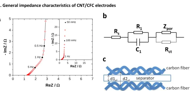
Figure 2. A typical impedance spectrum of cell with CNT/CF electrodes (a), equivalent circuit
(b), and illustration of the cell geometry: the electrolyte resistance varies along the electrode surface (c).
A typical impedance spectrum of a supercapacitor cell consisting CNT/CFC electrodes is shown in Fig.2.
The impedance spectrum exhibits typical characteristics of porous electrodes without Faraday processes. On the complex plane plot the most apparent feature is the pseudo-Warburg behavior above 1 Hz and the capacitive vertical line below this “frequency-of-the-knee”. This is very similar to
0 1 2 3 4 5 6 7
0 1 2 3 4 5
- ImZ / W
ReZ / W
1 Hz 0.5 Hz
5 Hz
a
0 5 10 15
0 5 10 15 20
- ImZ / W
ReZ / W 50 mHz
1 Hz 100 mHz
R
sR
1C
1Z
porR
ct6 that observed on VA-CNT on aluminum and nickel substrates [12, 13]; the interpretation is just the same. The element Zpor in the equivalent circuit in the inset of Fig.2 represents the impedance of the resistive pores coupled to the capacitive pore walls. Accordingly, the slightly modified version [24]
finite-pore impedance model of de Levie [25] can be used for the numerical evaluation. That model yields
𝑍
por(𝜔) = (𝑅W𝑗𝜔𝐶)𝑛coth[(𝑗𝜔𝑅W)𝑛]
(1)
which formula has an approximation form for the high frequency limit as
𝑍por(𝜔 → ∞) = (𝑅W𝑗𝜔𝐶)𝑛
(2)
and for low frequencies:
𝑍por(𝜔 → 0) = ( 1
𝑗𝜔𝐶)2𝑛+ 𝑅W
3
(3)
Note that the low frequency approximation, Eq.3. is a constant phase element (CPE) serially connected with the so-called pore resistance, 𝑅por = 𝑅W/3 . It is easy to show that the knee-frequency
𝑓knee = 1
2𝜋(𝑅W
𝐶)𝑛≅ 1
2𝜋√𝑅W
𝐶
(4)
The other elements – of less importance – of the equivalent circuit are as follows.
The Rs series resistance is mainly due to the electrolyte in the inter-electrode space, i.e. mostly within the separator; and to a lesser extent to the connections.
The parallel R1-C1 circuit is the modelling of a hump frequently appearing on the complex plane plots at the high frequency end of the spectra. This is due to that the carbon cloth has contact with the connector plates not everywhere along its rear side. If the rear side is perfectly contacted everywhere, e.g. it is covered by a thin sputtered gold layer, then this hump disappears and the R1-C1 pair is not needed for the modeling.
Rct: The CNT/CFC surface is perfectly blocking (unless the cell voltage is too high to start the decomposition of the electrolyte). Any decomposition would appear in the spectra as if the Rct were finite (unless otherwise noted, in our measurements, it is infinite).
The parameters of the equivalent circuit have been fitted to the measured spectra. The following values and trends are worth to be mentioned:
Cell capacitances: As seen on the typical impedance spectrum shown in Figure 2, the low frequency part of the spectra is almost vertical on the complex plane plot, accordingly, the spectra are close to the ideal behavior, n=0.47 - 0.493. Since this value is very close to 0.5, we ignore the difference between the CPE coefficient and a capacitance, and the former one is considered as cell capacitances.
Its value, normalized by CNT mass, for different CFC substrates is varying between 18 - 48 F/g. It is well below the achievable value of SWCNT of 80 F/g, which is a typical value in non-aqueous electrolytes [1]. The difference is probably due to the formation of MWCNT in some quantities, having lower accessible surface area.
We note that this exponent is, in general, somewhat smaller than those obtained with CNT/Al and CNT/Ni cells. We attribute this increased non-ideality to that the CNT-on-CFC has two, clearly distinguishable types of pores: the macropores of the cloth and the micropores between the nanotubes leading to broader time-constant distributions and hence lowering the exponents.
7 𝑓knee is in the order of magnitude of 1 Hz, it is two-three orders of magnitude smaller that those with CNT/Ni (100 Hz) and CNT/Al (1kHz). The reason is the much higher CNT mass load per geometric surface area.
The frequency range above 1 Hz (as a characteristic frequency of the knee) is affected both by double layer charging and ionic conductance inside the porous active layer. This range is more complex than the porous impedance element of CNT/Ni electrodes. The porosity of CNT/CFC electrodes consists at least two well-distinguishable parts, most probably ionic conductance between CNT tubes, and ionic conductance between fibers. The complexity of the cell geometry is illustrated in Fig.2b.
Resistances: The series resistance of CNT/CFC electrodes was found to be 0.75-0.930 Ohm×cm2, which is higher than the Rel for CNT/Ni electrodes (0.25 – 0.45 Ohm×cm2) [12]. The reason is the non-planar shape of woven fibers; therefore the average distance between the two electrodes is larger than the thickness of the separator. The pore resistance varying between 2 - 4.5 Ohm×cm2, which approx. 10 times larger than the same value in CNT/Ni or CNT/Al electrodes. The difference is originating from the larger CNT density, and longer electrolyte pathway between the electrodes.
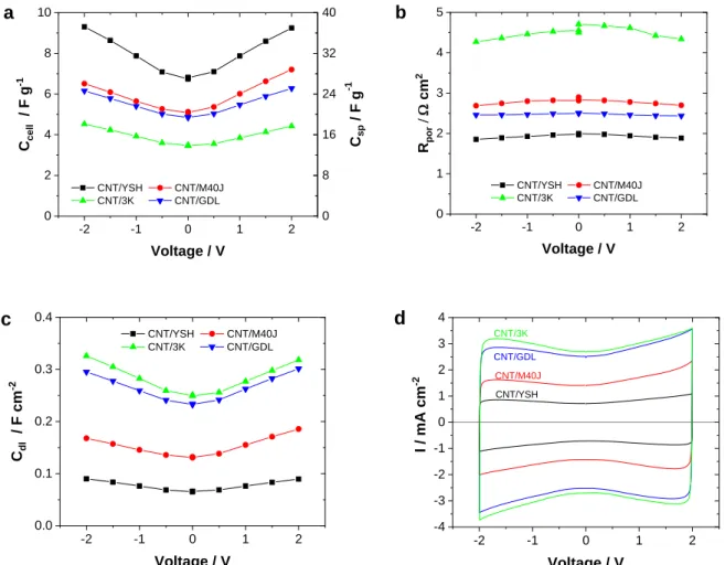
Figure 3.: Cell voltage dependence of the cell capacitance (a), of the double layer capacitance
(c), and of the pore resistance of CNT/CFC supercapacitors (b). CVs at 20 mV/s of supercapacitor cells assembled from CNT/CFC electrodes (d)
Voltage dependence: Impedance spectra have been recorded at different bias voltage values (from - 2V to 2V) in order to obtain information on the voltage dependence of double layer capacitance. The
-2 -1 0 1 2
0 2 4 6 8 10
CNT/YSH CNT/M40J CNT/3K CNT/GDL
Ccell / F g-1
Voltage / V
0 8 16 24 32 40
Csp / F g-1
a
-2 -1 0 1 2
0 1 2 3 4 5
CNT/YSH CNT/M40J CNT/3K CNT/GDL
Rpor/ W cm2
Voltage / V
b
-2 -1 0 1 2
0.0 0.1 0.2 0.3 0.4
CNT/YSH CNT/M40J CNT/3K CNT/GDL
Cdl / F cm-2
Voltage / V
c
-2 -1 0 1 2
-4 -3 -2 -1 0 1 2 3 4
I / mA cm-2
Voltage / V
CNT/3K
CNT/M40J CNT/GDL
CNT/YSH
d
8 double layer capacitance of CNT electrodes depends on the applied voltage as can be seen both on the fitted impedance data measured at different bias voltages (Figure 3a) and on the cyclic voltammograms (Figure 3d). The increase of capacitance with increasing voltage is a general characteristic of carbonous materials in organic
electrolytes being
attributed to several reasons.Salitra et al. [26] ascribe this observation to the potential dependence of the ion penetration into nanopores. Widely accepted explanation is the extension of the applied voltage into the carbon electrode causing a space charge [
2
7-29], or the dielectric constant increases with voltage [30]. The electrolyte resistance is independent of the applied voltage, while the pore resistance slightly decreases at higher voltages (Figure 3b). Latter can be explained by the influence of the electric field on migration process of ionic species. The shape of cyclic voltammetric curves (Figure 3d) shows the typical voltage dependence of double layer capacitance of carbonous materials in organic electrolytes.Furthermore, the absence of redox peaks on CVs indicates the electrochemical purity of CNT/CFC electrodes.
Figure 4. Apparent capacitance and resistance as a function of frequency. Data is obtained
from impedance spectra measured at 2V
Frequency dependence: Figure 4 shows the frequency dependence of the apparent capacitance and resistance, where C and R values are calculated from the measured impedance data according to C = - 1/(jωZ”) and R = Z’. The capacitance – frequency curve can be divided into two well-distinguishable ranges: (i) at low frequencies, f < 0.5 Hz for M40J, GDL, 3K, or f < 5 Hz for YSH, the capacitance is almost constant, the slight increase of capacitance with decreasing frequency is the result of the frequency dispersion due to macroscopic heterogeneity; (ii) at high frequencies, f > 0.5 Hz or f > 5 Hz, the penetrability of pores of active layer is decreasing with increasing frequency, therefore the capacitance is decreasing. The real part component of impedance is also increasing with decreasing frequency: (i) at f > 100 Hz, the serial resistance Rs (dominantly the electrolyte resistance) is measured; (ii) in the middle range of 0.1 – 1 Hz for GDL, 3K and M40J, or 0.5 – 5 Hz for YSH the plateau is relating to the sum of serial (electrolyte) resistance and the pore resistance, Rs + Rpor, where the ions are able to access the whole electrode surface deep inside the pores, with the result of a longer pathway for the ions in the electrolyte. (iii) At f < 100 mHz, a further increase of resistance occurs, which is a consequence of the real part component of the non-ideal CPE behavior of supercapacitor.
10-2 10-1 100 101 102 103 104 0
2 4 6 8 10
12 CNT/YSH CNT/M40J
CNT/3K CNT/GDL
Ccell / F g-1
f / Hz
a
10-2 10-1 100 101 102 103 104 0.00
0.05 0.10 0.15 0.20
CNT/YSH CNT/M40J CNT/3K CNT/GDL
Rcell / Ohm g
f / Hz
b
9 Figure 5.
Ragone plots calculated from impedance data. Values are given to active mass (a) and to total electrode mass (b)
The limit frequency (knee frequency), separating the ion transport controlled range and capacitive range, are much lower than for CNT/Ni electrodes, therefore CNT/CFC electrode supercapacitors can be used for lower frequency application.
Ragone plots were calculated from the measured impedance data as a function of frequency. The results are plotted in Figure 5. For comparison, the E energy and the P power densities of CNT/Ni electrode and a commercial activated carbon – on aluminum (AC/Al) electrodes measured in same supercapacitor cell assembly as the CNT/CF electrodes, are also presented. The P and E values have been calculated by normalizing to active mass in Figure 5a, and to total electrode mass in Figure 5b (including mass of electrode, electrolyte and separator, but excluding cell housing - this latter representation of data is more informative for practical application point of view). If we compare the frequency dependence of capacitance and resistance with CNT/Ni and AC/Al electrodes, we can conclude that the properties of CNT/CF electrodes are in between them, the power density is lower than CNT/Ni cells, and only little better than AC cells.
Substrat e
CNT mass / area [mg/cm
2]
CNT/
electrode mass ratio
C
cell[mF/cm
2]
C
cell[F/(g of active mass)]
C
cell[F/(g of electrode
mass)]
f
knee[Hz]
YSH 2.42 1 : 7 22 9.3 1.32 4
M40J 6.4 1 : 3.9 46 7.2 1.87 0.9
GDL 12 1 : 1.8 75 6.3 3.5 0.6
3K 18 1 : 2.5 80 4.5 1.75 0.4
0.1 1 10
104 105
106 CNT/YSH CNT/M40J CNT/GDL CNT/Ni AC/Al
P / W kg-1
E / Wh kg-1
65 mHz 130 mHz
650 mHz 16 Hz
80 mHz
a
0.1 1 10
104
105 CNT/YSH
CNT/M40J CNT/GDL CNT/Ni AC/Al ref
P* / W kg-1
E* / Wh kg-1
65 mHz 130 mHz 650 mHz
16 Hz
80 mHz
b
10
Sub-
strate
R
electrolyte[Wcm
2]
R
pore[Wcm
2cell]
R
pore[Wcm
2electrode]
Electrode thickness [m]
Pore volume [v/v%]
R
esr[Wcm
2] R
esr[mW (g active mass ]
R
esr[mW (g electro de mass)]
YSH 0.75 1.9 0.45 240 56 % 4.8 11.5 81
M40J 0.8 3.2 0.8 ND ND 3.6 23.2 90
GDL 1.05 2.75 0.69 450 46 % 3.8 58 105
3K 0.93 4.5 1.1 780 43 % 5.4 115 291
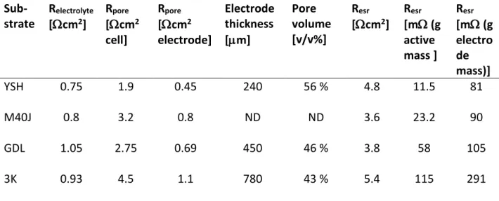
Table 1. Summary of capacitance and resistance values calculated from impedance spectra at
2V
Table 1 summarizes the capacitance and resistance values obtained for all the CNT/CFC samples. In general, the increase of CNT mass load results in an increase of double layer capacitance, which is also obvious on the obtained data. Comparing the specific capacitance of CNT on different CFC substrates, decrease of Csp with increasing CNT density was observed. The reason is the decrease of SWCNT/MWCNT ratio with increasing CNT mass/area. (This trend is similar to the observation of CNT/Ni with FeMo catalyst system [12].) The difference between specific capacitance values on different substrates is in agreement with the difference between CNT wall thicknesses, as seen on TEM images (Fig 6.). It seems to be also obvious, that increase of CNT mass density may be reached only at the expense of SWCNT/MWCNT ratio; there exists an optimum, at which the best electrochemical performance of supercapacitor can be found.
Figure 6. TEM images of CNT grown on different substrates - YSH (a), M40J (b), 3K (c), GDL (d)
The pore resistance increases with the increase of CNT density, but the correlation is less definite than in case of CNT/Ni samples. This is so, because the Rpore depends not only on CNT density, but also the thickness and structure of carbon fiber electrodes influences its values.
The cell capacitance, normalized to total electrode mass (CNT+CFC) gives better comparison for practical points of view. High cell capacitance was obtained with CNT/GDL and CNT/M40J electrodes approaching the cell capacitance of the reference activated carbon-on-aluminum electrode. This is the consequence of the large CNT mass load achieved on CFC substrate, and the low weight of the CFC.
The cell resistance of CNT/CFC electrodes remains below the reference, providing higher power application.
3.2. Galvanostatic charge/discharge cycle efficiency of CNT electrodes
11 Figure 7. Discharge capacity (a) and discharge/charge efficiency (b) as a function of current
density obtained with supercapacitor cells assembled from CNT/CFC electrodes
The cell capacity calculated from discharge current density (Fig7a) is in accordance with the impedance results, highest specific capacity was obtained for CNT/M40J electrodes, and lowest for CNT/3K. The discharge capacity is decreasing with increasing current density (with increasing power operation), as a result of limited ion accessibility at high current operation. The galvanostatic cycle efficiency depends on the current density, and the type of substrate, too. The efficiency of CNT/CFC electrodes are in between 92 – 98.9 %, and has a maximum as a function of current density at 0.1 - 0.15 A/g (Fig 7b). At I < 0.1 A/g the efficiency is decreasing due to the larger internal resistance at lower current density.
(At lower currents the charging time of capacitors are longer, and therefore the charge turning to a parallel electrochemical reaction - or dissipating due to heterogeneity - is higher, consequently, the energy loss is larger). This is analogous to the impedance results, where the resistance is increasing at f < 100 mHz; the real part component of impedance is larger, due to heterogeneity (see frequency dependent impedance data above in Figure 4b). At I > 0.15 A/g the efficiency decreasing with increasing current density: less part of the total pore surface area is charged at higher current densities (the capacitance is more influenced by the ionic transport inside the pores), while the resistance is near constant (see plateau of resistance near to 200 mHz on Fig4b). As a result, the efficiency is decreasing with increasing current density. The same trend is valid for CNT/YSH, with the difference that the maximum efficiency of 98 % can be reached at 0.2 A/g current density. This is in accordance with the higher knee frequency of CNT/YSH, cf Table1.
3.3. Cycle stability
Long-term galvanostatic charge-discharge cycle stability test series were performed up to 1 million cycles with 1A/g charging/discharging rate with supercapacitors built from CNT/M40J electrodes (mCNT
= 6.4 mg/cm2) assembled in a hermetically sealed CR-2032 type coin cell. The cycle stability tests were paused in several times, in order to measure CV and impedance in between to obtain diagnostic data on the supercapacitor aging properties. The results of the galvanostatic charge/discharge measurement are summarized on Figure 8. The cell capacity is 5.8 F/g and the cycle efficiency is 0.93, and both can be considered to be stable up to 1 million cycles, indicating that there is no any change in the operation performance of supercapacitor. Similarly long cycle life of 100 000 cycles with capacitance retention of 99% has already been presented by Zhou et al using CNT/CC electrodes with H3PO4/poly(vinyl alcohol) electrolyte [15].
0.0 0.2 0.4 0.6 0.8 1.0
0 2 4 6 8 10
YSH M40J 3K GDL
Ccell / F g-1
I / A g-1
a
0 8 16 24 32 40
Csp /F g-1
0.0 0.2 0.4 0.6 0.8 1.0
0.90 0.92 0.94 0.96 0.98 1.00
YSH M40J 3K GDL
Efficiency
I / A g-1
b
12 Figure 8: Cell capacitance and cycle efficiency (a), internal cell resistance (b), energy and power
density over charge / discharge cycles for CNT/CFC calculated to active mass (c) and electrode mass (d)
Figure 9:
Impedance spectra (a) and cyclic voltammograms (b) over charge/discharge cycles during long-term stability tests at cycle numbers as indicated. Electrodes: 6.4 mg/cm
2VA-CNT on M40J
0 200 400 600 800 1000
0 1 2 3 4 5 6 7
Ccell / F g-1
1000 GCD cycles
0.80 0.82 0.84 0.86 0.88 0.90 0.92 0.94 0.96 0.98 1.00
Efficiency
Ccell
Efficiency
a
0 200 400 600 800 1000
0.00 0.02 0.04 0.06 0.08 0.10 0.12
Resr/ W g
1000 GCD cycles
b
0 200 400 600 800 1000
0 1 2 3 4 5 6 7
E / Wh kg-1
1000 GCD cycles
0 5000 10000 15000 20000
P / W kg-1
Energy Power
c
0 200 400 600 800 1000
0.0 0.2 0.4 0.6 0.8 1.0
E* / Wh kg-1
1000 GCD cycles
values calculated to electrode mass 0 1000 2000 3000 4000 5000 6000
P* / W kg-1
Energy
Power
d
0 2 4 6 8 10 12 14
14 12 10 8 6 4 2 0
2 000 55 000 110 000 160 000 270 000 450 000 600 000 950 000
Re Z / W
- ImZ / W
a
2 000 950 000
-2 -1 0 1 2
-0.008 -0.006 -0.004 -0.002 0.000 0.002 0.004 0.006
2 000 55 000 110 000 160 000 270 000 450 000 600 000 950 000
I / A
Voltage/ V
b
2 000
950 000 950 000
2 000
13 Figure 10: Change of fitted impedance parameters over galvanostatic charge / discharge
(GCD) cycles for CNT/CFC. Electrodes: 6.4 mg/cm
2VA-CNT on M40J
The fitted impedance data (Figure 10) reflects better the stability of supercapacitor test device. The n value of the modified de Levie element, which characterizes the uniformity of the system, is constant, suggesting that there is no sign of degradation of electrode material at all. After an initial small decrease, the internal serial resistance, which is the sum of electrolyte and pore resistance, is also constant, 37 m g, indicating that there is no change of the pore structure and electrolyte composition during operation. The only change in the impedance parameters during long-term charge/discharge cycle stability test is the increase of double layer capacitance at and near 0 V. During charging and discharging supercapacitors, cyclic expansion and shrinkage in the volume of active layer take place, respectively, corresponding to swelling and contraction of CNT bundles. This is a reversible process in short-term potential cycling, as it has been demonstrated with electrochemical dilatometry
0 200 400 600 800 1000
5 6 7 8
0V 2V
Ccell / F g-1
1000 GCD cycles 2V
2V
20 24 28 32
Csp / F g-1
a
0 200 400 600 800 1000
0 10 20 30 40 100 150 200 250
2V 0V
Rc t / kW
1000 GCD cycles 2V
0V
b
0 200 400 600 800 1000
0 10 20 30 40 50 60 70 80
0V 2V
Resr / W g
1000 GCD cycles
c
0 200 400 600 800 1000
0.48 0.49 0.50
0V 2V
n
1000 GCD cycles 2V
0V
d
0 200 400 600 800 1000
1.0 1.1 1.2 1.3 1.4 1.5 1.6
0V 2V
fknee / Hz
1000 GCD cycles 0V
2V
e
14 measurements by Ruch et al. [31]. During long-term operation conditions this continuous cyclic volumetric change may result in a very slow structural transformation since both the electrode material and CNT layer is flexible. Because the size of the anion (BF4-, 0.46 nm) and cation (TEA+, 0.68 nm) used for charging are different, the change in the structure of the positive and negative electrodes will be also different. Thus, over time, the originally symmetrical cell with same quality of electrodes becomes asymmetric. This assumption is supported by the change of the shape of CVs (Figure 9a), where the cathodic part of CV became somewhat broader, than the part at anodic potentials.
Furthermore, ion intercalation into the carbon fiber is also possible.
In summary, excellent cycle stability performance was obtained for VA-CNT/CFC electrodes. The stability measurements were performed up to 1 million galvanostatic charge/discharge cycles, and no decrease of capacitance, no decrease of cycle efficiency and no increase of internal resistance was observed. The major reason of such excellent stability is the inert electrochemical nature of CFC substrate, namely no any charge transfer process of corrosion origin influences the life-time of supercapacitor cell.
3.4. Specific values
The obtained electrochemical data allow us to estimate the two most important practical parameters of the supercapacitor cells - the energy density E and power density P. We gave two estimations of these specific parameters in Table 2, one with normalized by the CNT mass, the other with normalization of the mass of the functional elements (sum of masses of CNT, substrate, separator and electrolyte – but excluding the housing and electrode connections).
The energy and power density of the investigated CNT/CFC electrodes (calculated to CNT mass) vary between 3 – 7 Wh/kg and 10 – 100 kW/kg, respectively, while the E and P values, calculated to total electrode mass are vary between 3 – 7 Wh/kg and 0.8 - 1.5 Wh/kg, respectively.
The power density of the CNT/Ni and CNT/Al EDLCs normalized to electrode mass are approximately 30 kW/kg and 80 kW/kg, respectively, and practically independent on the density of CNT layer [12, 13]. This is 1-2 orders of magnitude higher than the typical power density of supercapacitors made from activated carbon (0.5 – 10 kW/kg). This is due to the very low internal resistance of CNT supercapacitors owing to the fast ion-transfer process in the inter-tube channels of aligned CNT layers, high electronic conductivity of the CNTs, and direct binder-free contact between CNT layer and aluminum substrate. On the other hand, the energy density varies between 0.1 – 0.15 Wh/kg depending on the density of the CNT layer. This is one magnitude lower than the energy density which can be reached with AC electrodes 1 – 10 Wh/kg. The major reason of the lower energy density was the loose packing of tubes in the active layer resulting low density of 0.15 – 1 mg/cm
2; in contrast, the AC based electrodes have a typical active mass loading around 10 mg/cm
2. Our electrochemical results indicate the advantage of VA-CNT supercapacitors in applications that require high power density or used at high frequencies.
Much higher energy density is obtained for CNT/CFC supercapacitors, the 0.8 – 1.5 Wh/kg is
one magnitude higher than the energy density obtained for VA-CNT on aluminum or nickel,
and only little lower than the typical energy density of commercial supercapacitors made from
activated carbon (Table 2). The reason of it is the higher CNT density on the carbon fibers
calculated to geometric surface area. The power density is varying between 5 -20 kW/kg,
which is lower than the P of CNT/Al or CNT/Ni electrodes but still higher than the P of
commercial AC/Al electrodes; these electrodes allows high charging-discharging rate
15
application with appropriate energy density. Due to the large CNT density and light weight of substrate, the resulted CNT/substrate mass ratio is high, varying between 1:1.8 to 1:18.
Consequently, the energy and power density values, calculated to electrode level, is also high, which is very important from practical point of view. Therefore, the largest drawback, namely the loose packing of CNT directly grown on Al or Ni (where the CNT/substrate mass ratio was around 1:100), could be eliminated, too, with applying carbon cloths as substrates for CNT electrodes.
All the same, the major advantage of CNT/CFC electrodes against the commercial AC/Al electrodes stands in the inert nature of substrate material, that is, due to the absence of corrosion process the supercapacitors built from CNT/CFC electrodes has uniquely good cycle stability performance.
parameter CNT/nickel CNT/aluminum CNT/carbon fibre
Commercial AC Energy density
(CNT mass) 2 – 8 Wh/kg 3 – 8 Wh/kg 3 – 7 Wh/kg Power density
(CNT mass)
1000 – 3000
kW/kg
2000 – 6000
kW/kg 10 – 100 kW/kg Energy density
(electrode mass)
0.1 Wh/kg0.1 - 0.15 Wh/kg 0.8 - 1.5 Wh/kg 1 - 10 Wh/kg Power density
(electrode mass) 30 kW/kg 80 kW/kg 5 – 20 kW/kg 0.5 – 10 kW/kg
Table 2: Comparison of results obtained for CNT films on nickel, aluminum foil, and carbon fibre
4. Summary and conclusions
The electrochemical characteristics of double layer capacitors built form CNT grown directly on some selected commercially available carbon cloth substrates has been studied. The CNT mass load was varying between 2 - 18 mg/cm
2, and the resulted CNT/electrode mass ratio was in between 1:1.8 to 1:8. MWCNT films gave specific capacity from 18 to 48 F/g. Low serial resistance 10 – 100 mW.cm
2was observed, attributed to fast ion-transport in the inter-tube channels, to high electronic conductivity of the tubes, and good electric contact of the tubes with the substrate. Energy density of 0.8-1.5 Wh/kg on electrode level was calculated. Power density was as high as 5-20 kW/kg.
Outstanding cycling stability was observed: The values for CNT/carbon fiber electrodes were
stable over 1 million cycles. This result can be attributed to the more stable surface of CNTs
as compared to active carbon, but also the inert, metal-free electrode approach helps to avoid
corrosion and other degradation effects related to the metal–carbon interface.
16 Acknowledgement
The atmospheric pressure CVD process line was developed and VA-CNT electrodes were prepared by Susanne Dörfler, Benjamin Schumm, Althues Holger and Stefan Kaskel at the Fraunhofer Institute for Material and Beam Technology, IWS, Dresden, Germany, their collaboration is gratefully acknowledged. Authors are also thankful to P. Németh (RCNS-HAS, Budapest) for taking SEM and TEM images, and for Lajos Nyikos for help and advice. The research within project No. VEKOP-2.3.2-16-2017-00013 was supported by the European Union and the State of Hungary, co-financed by the European Regional Development Fund.
Financial assistance of the PLIANT (Process Line Implementation for Applied Surface Nanotechnologies) FP7 project (No. 309530), and OTKA K112034 is acknowledged.
References
1 D.N. Futaba, K. Hata, T. Yamada, T. Hiraoka, Y. Hayamizu, Y. Kakudate, H. Hatori, M.
Yumura, S. Iijima, Shape-engineerable and highly densely packed single-walled carbon nanotubes and their application as super-capacitor electrodes, Nature Materials, 5 (2006) 987.
2 Hao Zhang, Gaoping Cao, Yusheng Yang, Electrochemical properties of ultra-long, aligned, carbon nanotube array electrode in organic electrolyte, J. Power Sources 172 (2007) 476.
3 P.W. Ruch, L.J. Hardwick, M. Hahn, A. Foelske, R. Kötz, A. Wokaun, Electrochemical doping of single-walled carbon nanotubes in double layer capacitors studied by in situ Raman spectroscopy, Carbon 47 (2009) 38.
4 Chunsheng Du and Ning Pan, High power density supercapacitor electrodes of carbon nanotube films by electrophoretic deposition, Nanotechnology 17 (2006) 5314.
5 Fu Zhao, Antonello Vicenzo, Mazdak Hashempour, Massimiliano Bestetti, Supercapacitor electrodes by direct growth of multi-walled carbon nanotubes on Al, Electrochim. Acta 150 (2014) 35.
6 Radu Reit, Justin Nguyen, W. Jud Ready, Growth time performance dependence of vertically aligned carbon nanotube supercapacitors grown on aluminum substrates, Electrochim. Acta, 91 (2013) 96.
7 C. Arbizzani, M. Mastragostino, F. Soavi, New trends in electrochemical supercapacitors, J. Power Sources 100 (2001) 164.
8 S. Iijima, Helical microtubules of graphitic carbon, Nature 354 (1991) 56.
9 E. Frackowiak, K. Metenier, V. Bertagna and F. Beguin, Supercapacitor Electrodes from Multiwalled Carbon Nanotubes, Applied Physics Letters 77 (2000) 2421.
10 H. Zhang, G. P. Cao and Y. S. Yang, Using a Cut-Paste Method to Prepare a Carbon Nanotube Fur Electrode, Nanotechnology 18 (2007) 195607.
11 S. Talapatra, S. Kar, S. K. Pal, R. Vajtai, L. Ci, P. Victor, M. M. Shaijumon, S. Kaur, O.
Nalamasu and P. M. Ajayan, Direct growth of aligned carbon nanotubes on bulk metals, Nature Nanotechnology, 1 (2006) 112.
12 S. Dörfler, I. Felhösi, I. Kék, T. Marek, H. Althues, S. Kaskel, L. Nyikos, Tailoring structural
and electrochemical properties of vertical aligned carbon nanotubes on metal foil
using scalable wet-chemical catalyst deposition, J. Power Sources 208 (2012) 426.
17
13 S. Dörfler, I. Felhösi, T. Marek, S. Thieme, H. Althues, L. Nyikos, S. Kaskel, High power supercap electrodes based on vertical aligned carbon nanotubes on aluminum, J.
Power Sources 227 (2013) 218.
14 Y.K. Hsu, Y.C. Chen, Y.G. Lin, L.C. Chen, K.H. Chen, High-cell-voltage supercapacitor of carbon nanotube/carbon cloth operatingin neutral aqueous solution, J. Mater. Chem.
22 (8) (2012) 3383–3387.
15 C. Zhou and J. Liu, Carbon nanotube network film directly grown on carbon cloth for high-performance solid-state flexible supercapacitors, Nanotechnology 25 (2014) 035402
16 Z. Jiao, Q. Wu, J. Qiu, Preparation and electrochemical performance of hollow activated carbon fiber - Carbon nanotubes three-dimensional self-supported electrode for supercapacitor, Materials and Design 154 (2018) 239–245.
17 L. Wang, H. Yang, G. Pan, L. Miao, S. Chen, Y. Song, Polyaniline-Carbon Nanotubes@Zeolite Imidazolate Framework67-Carbon Cloth Hierarchical Nanostructures for Supercapacitor Electrode, Electrochimica Acta 240 (2017) 16–23 18 J.H. Liu, X.Y. Xu, W. Lu, X. Xiong, X. Ouyang, C. Zhao, F. Wang, S.Y. Qin, J.L. Hong, J.N.
Tang, D.Z. Chen, A high performance all-solid-state flexible supercapacitor based on carbon nanotube fiber/carbon nanotubes/polyaniline with a double core-sheathed structure, Electrochimica Acta, 283 (2018) 366-373
19 M. Zou, W. Zhao, H. Wu, H. Zhang, W. Xu, L. Yang, S. Wu, Y. Wang, Y. Chen, L. Xu, and A. Cao, Single Carbon Fibers with a Macroscopic-Thickness, 3D Highly Porous Carbon Nanotube Coating, Adv. Mater. 2018, 30, 1704419
20 C.T. Hsieh, D.Y. Tzou, W.Y. Lee, J.P. Hsu, Deposition of MnO2 nanoneedles on carbon nanotubes and graphene nanosheets as electrode materials for electrochemical capacitors, Journal of Alloys and Compounds 660 (2016) 99-107
21 Z. Zhang, H. Wang, Y. Zhang, X. Mu, B. Huang, J. Du, J. Zhou, X. Pan, E. Xie, Carbon nanotube/hematite core/shell nanowires on carbon cloth for supercapacitor anode with ultrahigh specific capacitance and superb cycling stability, Chemical Engineering Journal 325 (2017) 221–228
22 S. Wang and R.A.W. Dryfe, Graphene oxide-assisted deposition of carbon nanotubes on carbon cloth as advanced binder-free electrodes for flexible supercapacitors, J.
Mater. Chem. A, 2013, 1, 5279
23 S. Dörfler, A. Meier, S. Thieme, P. Németh, H. Althues, S. Kaskel, Wet-chemical catalyst deposition for scalable synthesis of vertical aligned carbon nanotubes on metal substrates, Chem. Phys. Letters 511 (2011) 288.
24 R. Kötz, M. Karlen, Principles and Applications of Electrochemical Capacitors, Electrochim. Acta 46 (2000) 2483.
25 R. de Levie, in: P. Delaray, C.T. Tobias (Eds.), Advances in Electrochemistry and Electrochemical Engineering, 6, Interscience, NY, 1965, p.329
26 G. Salitra, A. Soffer, L. Eliad, Y. Cohen, D. Aurbach, Electrolytes in porous electrodes, Effects of the pore size and the dielectric constant of the medium J. Electrochem. Soc.
147 (2000) 2486.
27 P.W. Ruch, L.J. Hardwick, M. Hahn, A. Foelske, R. Kötz, A. Wokaun, Electrochemical
doping of single-walled carbon nanotubes in double layer capacitors studied by in situ
Raman spectroscopy, Carbon 47 (2009) 38.
18