sケョ・イァゥウエゥ」@・ヲヲ・」エウ@ッヲ@」。イ「ッョ@ョ。ョッエオ「・ウ@ッョ@エィ・@ュ・」ィ。ョゥ」。ャ@ーイッー・イエゥ・ウ@ッヲ@「。ウ。ャエ@。ョ、
」。イ「ッョ@ヲゥ「・イMイ・ゥョヲッイ」・、@ーッャケ。ュゥ、・@V@ィケ「イゥ、@」ッューッウゥエ・ウ sコ。ォ£」ウ@jNL@m←ウコ£イッウ@lN
a」」・ーエ・、@ヲッイ@ーオ「ャゥ」。エゥッョ@ゥョ@jッオイョ。ャ@ッヲ@tィ・イュッーャ。ウエゥ」@cッューッウゥエ・@m。エ・イゥ。ャウ pオ「ャゥウィ・、@ゥョ@RPQX
doiZ@QPNQQWWOPXYRWPUWQWWQSPUU
Synergistic effects of carbon nanotubes on the mechanical properties of basalt and carbon fiber reinforced polyamide 6 hybrid composites
József Szakácsa, *; László Mészárosa, b
a Department of Polymer Engineering, Faculty of Mechanical Engineering, Budapest University of Technology and Economics, Muegyetem rkp. 3. T bld. III., H-1111 Budapest, Hungary
b MTA–BME Research Group for Composite Science and Technology, Muegyetem rkp.
3., H-1111 Budapest, Hungary
* corresponding author, e-mail: szakacs@pt.bme.hu,
Phone: +36-1-463-1525 Fax: +36-1-463-1527 ABSTRACT
In this study a new type of carbon nanotube (CNT) and micro fiber (carbon or basalt) reinforced polyamide 6 hybrid composites were prepared and investigated. Hybrid composites were produced by melt compounding and specimens were injection molded.
Thanks to the proper dispersion of CNT, a remarkable increment in tensile properties was exhibited. The scanning electron microscopy of the fracture surfaces of the tensile tested materials revealed that during composite preparation the presence of the fibers in the melt facilitated a better dispersion of the CNT, which explains the enhancement in the tensile properties. The deformation components of the materials were also examined at different load levels. The presence of carbon nanotubes decreased residual deformation at every applied load level. Protruding fiber length investigation revealed that improved mechanical properties are not related to fiber-matrix adhesion but to the reinforcing and stress homogenization effect of nanotubes in the matrix.
INTRODUCTION
The spread of polymer matrix composites in the industry is continuous owing to their excellent mechanical properties and relatively small density. Besides thermoset composites, this is also true for thermoplastic matrix ones. The injection molding of thermoplastic composites is a widely used technology in the electronic and automotive industry, because these growing industries have high production demands 1 . The most commonly used reinforcing material is glass fiber 1 2 , although carbon fibers are also applied in large amounts due to their high strength and modulus. Together, Polyamide 6 and carbon fiber can reach high strength and modulus 3 4 . Nevertheless, a market breakthrough has not come yet for carbon fiber, since its price is relatively high. Another competitor of glass fiber can be basalt fiber, which has similar mechanical properties to glass fiber, but its thermal and chemical resistance is far better and its production is simpler as well, therefore it can become a real alternative to glass fiber in the field of composites in the future 5 6 .
In the last few decades different types of nanoparticles have been discovered. The industrial-scale manufacturing of some of these materials is now possible, thus the application of these particles is increasing 7 8 . Graphene and carbon nanotubes are the most popular nowadays, since they have outstanding mechanical properties, and at the same time, their thermal and electric conductivity are also remarkable 8 9 10 11 . If these particles are applied, the strength properties of polymer composites can also be improved
in an efficient way 12 13 14 15 16 , but these results are still far below expectations. A reason is that nanocomposites are difficult to produce since nanoparticles have a high tendency to aggregate. The best particle dispersion methods such as the surface treatment of particles and sonication in the monomer, and polymerization afterwards is hard to implement on an industrial scale 17 .
The widespread application of nanoparticles and fibers opened new possibilities for composite development and with their combined application so-called hybrid composites can be created. The aim of hybridization is to enhance the strength properties of composites or to provide other functional properties 18 19 20 21 .
In the case of thermoplastic matrix composites, thanks to the presence of fibers during processing, higher shear forces awake in the matrix22 23 , and that may help the dispersion of particles 24 25 26 27 . The strength-increasing effect of nanoparticles in hybrid composites can have various reasons. On one hand particles can have a significant effect on the matrix, e.g. on the crystalline structure of semi-crystalline polymers 28 29 . An increase in crystallinity results in the strength improvement of the matrix as well. Nanoparticles may reduce average crystallite size and that increases impact strength 30 . Adequately dispersed nanoparticles may act as reinforcement, i.e. take up the load of composites, and this way increase their strength and may slow down crack propagation 31 . According to some assumptions, they homogenize stress that evolves in the system and therefore increase the resistance of composites against mechanical loading 32 33 . Nanoparticles may influence
microfiber-matrix connection as well. If they appear in the interphase, they may enhance load transfer among microfibers and the matrix, and this way improve the interlaminar shear strength of composites. This phenomenon can be observed in the case of similar nanoparticles and fibers (glass fiber, clay), and may occur spontaneously during composite production 34 35 36 .
The production of hybrid composites may hold several possibilities. Our aim in the present research is to produce polymer matrix composites that contain different kinds of microfibers and carbon nanotubes, with methods that can be applied on an industrial scale as well. In this study basic mechanical properties are examined, and the dispersion of the particles are presented. Matrix and fiber adhesion are determined by scanning electron microscopy and protruding fiber length, and the ratio of elastic and plastic deformation components are also revealed with the help of a special cyclic test.
EXPERIMENTAL Materials
Schulamid 6 MV 13 type polyamide 6 (PA 6) from A. Schulman GmbH (Germany) was used as matrix material. BCS KV02 type basalt fiber (BF) from Kamenny Vek Ltd.
(Russia) and Panex 35 type 95 carbon fiber (CF) from Zoltek Zrt (Hungary) was applied as micro-sized reinforcement. The initial length of both fibers was 6 mm. The average diameter of basalt fibers was 15.6±1.9 μm and that of carbon fibers was 8.3±1.0 µm. NANOCYL NC7000 carbon nanotubes supplied by Nanocyl SA. (Belgium) were used
as nano-size reinforcement. Nanotubes had an average length of 1.5 µm and an average diameter of 9.5 nm. The minimal carbon purity of nanotubes was 90% and nanotubes had no surface treatment.
Sample Preparation
A Labtech Scientific type twin screw extruder (L/D=44; D=26 mm) was used for continuous melt mixing. The screw speed was 25 1/min and extrusion temperature was 250 °C. 30 wt% BF or CF and 0.25; 0.5; 0.75 and 1 wt% CNT was used for the different composites (Table 1.). Dried PA 6 granulates (80 °C; 4 hours) were mechanically mixed with the reinforcing materials for two minutes, and every 5 minute they were remixed for 10 seconds to avoid settling, then extruded and granulated (particle size: 4.5 mm).
Dumbbell type specimens (1A type according to the ISO 527-2 standard) were injection molded on an Arburg Allrounder Advance 370S 700-290 injection molding machine.
Injection molding temperature was 275 °C and maximal pressure was 800 bar. Mold temperature was set to 80 °C.
Characterization methods
Before the mechanical tests, the specimens were conditioned at 50% relative humidity at room temperature for a month, then the temperature was set to 25 °C (besides 50%
relative humidity) for a further week. Tensile tests were performed on a Zwick Z020 universal testing machine according to EN ISO 527. The crosshead speed was 5 mm/min during tensile tests and at least 5 specimens were tested from each material type.
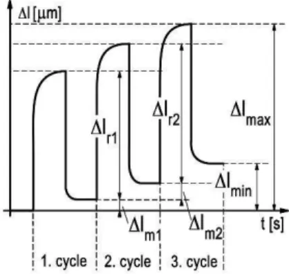
The ratio of the deformation components at different load levels was determined with special cyclic mechanical deformation tests. The conditioning process before the test was the same as in the case of tensile tests. These tests were also performed on a Zwick Z020 universal testing machine. Loading speed (both down and up directions) was set to 100 N/s. Loading force was increased by 100 N in every cycle, and after load removal there was a 30 s relaxation time. Residual deformation was determined with equation 1 where Δlminn is the minimum elongation in the current cycle, Δlmin(n-1) is the minimum elongation in the previous cycle, and ∆l0 is the starting length (starting grip to grip separation). The ratio of elastic recovery was determined with equation 2 where ∆lmaxn is the maximum deformation in the current cycle. These values were determined from the displacement- time diagraph (Fig. 1).
� � � =∆�∆� +∆�i −∆� i −
i − [−] (1)
� ��% � = ∆� ax∆� −∆� i
ax ∙ [%] (2)
Fiber length distribution was measured. Fibers were burned out from the matrix at 500
°C for 1 hour, then the recovered fiber length was measured with an Olympus BX51 optical microscope. Fiber length distribution was determined from the length data of ca.
1500 fibers. The fiber orientation of the samples was also investigated with this microscope: injection molded specimens (three per material type) were cut at a specific point (from the ordinary fracture site) and polished. On this surface the major and minor
The fracture surfaces of the broken tensile tested specimens were sputtered with a thin gold layer, and investigated with a Jeol 6380 LA type scanning electron microscope (SEM). Pictures were also taken from a perpendicular direction to the tensile axis to determine the protruding length of the fibers. To determine the length histogram at least 250 fibers were measured.
The crystallinity of the materials was determined by differential scanning calorimetry (DSC, TA Instruments Q2000). For the measurements, samples were cut from the middle of dumbbell specimens. The degree of crystallinity (Xc) was calculated with the following equation:
�� =����
�∙ 1−� [%], (3.5.)
where ΔHm is the melting enthalpy, ΔHm is the average melting enthalpy of 100%
crystalline polyamide 6, and φ is the fiber content in mass%.
RESULTS AND DISCUSSION Conventional tensile tests
The results of conventional tensile tests can be seen in Table 2. In the case of nanocomposites, no significant change was found, either in strength or in modulus values compared to the neat matrix. The presence of particles decreased both values to a small extent, i.e. particles could not exert their reinforcing effect. The reason might be inadequate dispersion. Shearing in the melt during processing was not enough to break
up all of the aggregates. Strain at break was reduced at only 1 w% CNT content, thus particles did not typically make the composite rigid. An investigation of the stress-strain curves (Fig. 2.) revealed major differences between the polyamide 6 and its composites.
In the case of nanocomposites, the maximal stresses were nearly the same (as the tensile strength value shown earlier) but it was reached at higher deformation; contraction occurred later. This means nanocomposites were more ductile, which can cause higher energy absorption during deformation (Table 3.). Results in the case of hybrid composites were different. The strength of composites reinforced with basalt or carbon fiber increased when carbon nanotubes were added, and if the fact that nanotubes themselves decreased these values is considered, synergistic effects can be assumed. In both cases maximal strength was experienced at 0.5 wt.% CNT content. The value of tensile strength reached 112 MPa in the case of the basalt fiber-reinforced hybrid, while the tensile strength of the composite that contained only basalt fiber was only 102 MPa. In the case of carbon fiber reinforcement this value increased from 179 MPa to 198 MPa. This means an increase of ca. 10% in both hybrid systems. In both cases the nanoparticle did not change the characteristic of the stress-strain curves significantly. At larger CNT content moderate decrease was experienced, therefore CNT content is not worth increasing further. A similar tendency could be observed when Young’s moduli of composites were examined.
During the manufacturing of hybrid composites CNT dispersion could improve it owing to the presence of fibers and that explains the improvement in mechanical properties. The
value of strain at break decreased significantly compared to polyamide when basalt and carbon fibers were applied, although this value did not decrease further when CNT was added, meaning that the effect of the microfibers was dominant. This refers to the fact that nanoparticles did not influence the fiber-matrix interaction but caused strengthening by modifying the properties of the matrix.
Morphology of the composites
In order to examine the morphology of the produced composites scanning electron micrographs were taken from the fracture surfaces which were formed during the tensile test, and DSC analysis was performed to reveal the crystallinity in the composites. The fracture of neat polyamide 6 (Fig. 3 A) and the fracture of nanocomposites were fully ductile, but during the examination of the fracture surfaces of nanocomposites large aggregates were observed (Fig. 3 B). As carbon nanotube content was increased, not necessarily larger but more aggregates were found on the surface, and they were usually the starting points of failure (Fig. 3 C). At higher magnification it can be seen that these aggregates are partly impregnated with the matrix (Fig. 3 D), therefore these are partly dispersed and intercalated nanocomposites, but CNT is still not capable of modifying properties in a positive way. The mechanical properties of these areas significantly differ from the properties of the matrix that surrounds them, therefore aggregates act as a starting point of failure during loading, and not as reinforcement.
Fig. 4 shows typical fracture surfaces of microfiber-reinforced and hybrid composites.
Both micro ductile and micro brittle failures were found on each surface. If microfiber and hybrid composites are compared, no significant difference can be observed between the characteristic of failure, let that be basalt-based (Fig. 4 A and B) or carbon fiber-based (Fig. 4 D and E) composites. Based on the examination of fracture surfaces, it can be stated that fiber-matrix adhesion was adequate in the case of both fibers, also recognized in the case of hybrid composites, while nanoparticles had no impact that can be revealed by microscopy. Compared to nanocomposites, no large size aggregates can be seen on the surface of hybrid materials, as the presence of fibers aided the decomposition of aggregates and a better dispersion of particles during processing. These well-dispersed carbon nanotubes can be seen in Figs. 4 C and 4 F on the surface of basalt and carbon fiber-reinforced hybrid composites. These dispersed particles may form an adequate connection with the matrix, and therefore influence its strength properties.
The crystallinity of the matrix can also affect the mechanical properties of the composites
30 37 38 , therefore all manufactured composites were investigated by DSC. The size of carbon nanotubes is comparable with the size of the polymer chains, hence the presence of nanoparticles may have a major impact on the morphology 39 . They can act as a nucleating agent, but on the other hand, well dispersed particles may block the growth of crystals. The effect of these particles always depends on the properties of the surrounding system and processing parameters. The study of the nanocomposites revealed that CNT
did not have a notable influence on the crystallinity of polyamide 6, only a slight decrease of this value was found at higher CNT content (Table 2.). The same tendencies were found in the case of both fiber-reinforced composites and their hybrids. It should be noted that in case of basalt fiber containing composites lower crystallinity were calculated. The better dispersion of the nanoparticles has no significant effect on the crystallinity of hybrid composites, thus the increase of the strengths and the moduli were not in strong connection with crystallinity change.
Examination of fibers
Fiber properties, fiber length formed during processing and also fiber distribution have an impact on the mechanical properties of composites. The diameter of the basalt fiber applied was double that of the carbon fibers, that is why the initial aspect ratio of basalt fibers was nearly half that of carbon fibers (Table 4.). The tensile strength and modulus of carbon fiber are also twice those of basalt fiber. The difference between the densities caused a higher volume ratio of carbon fiber, and this higher volume ratio and higher modulus caused the higher strength and modulus of the carbon fiber composite.
Besides processing parameters, added CNT may also affect fiber length distribution, since owing to their large specific surface, they may increase the viscosity of the melt, and this way increase shearing in the melt. Melt flow index investigations (Fig. 5) revealed that CNT highly decreased the flowability of polyamide 6, but in connection with further results, this increased shearing was not enough to break up the aggregates. Microfibers
had a significant effect on MFI. Basalt fiber halved its value, while the MFI of carbon fiber composites was 17.1 g/10 minutes. Adding CNT to these systems further decreased this value. On one hand, this aids aggregate decomposition, but on the other hand, it may result in fiber breakage.
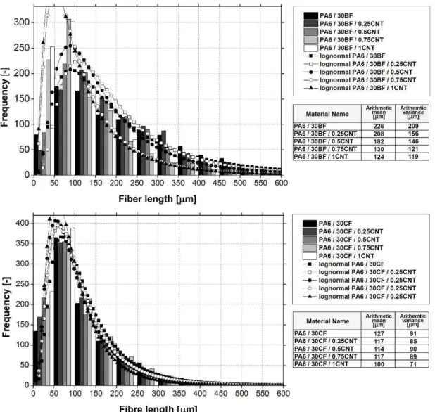
The length distribution of fibers was approximated with a log-normal function 40 . In the case of basalt fiber composites, it can be seen that if CNT content increased, the amount of shorter fibers also increased (Fig. 6). This could be the reason why in the case of larger CNT content strength decreases. A reduction in the arithmetical mean of the fitted log- normal function also confirms this phenomenon. Thanks to the fiber length decrement, the aspect ratio of the fibers also decreased. The aspect ratios changed from 385 to 14.5 in the case of the basalt fiber composite, and it decreased to 7.9 at 1 m% CNT content.
Based on the analysis of the log-normal distribution fitted on the frequency function, it can be stated that carbon fiber suffered more breakage than basalt fiber during processing (the initial fiber length was 6 mm in both cases). A CNT content of 0.25% decreased fiber length further, but the extent was smaller than in case of basalt fiber composites. In spite of higher breakage, the aspect ratio of carbon fibers was slightly higher (~15.3) than that of basalt fibers. A slightly higher aspect ratio and higher mechanical strength also explains the observed higher strength of carbon-fiber composites. When CNT content was increased, up to a value of 0.75%, fiber length did not change significantly, then at 1% CNT content a smaller decrease occurred (Fig. 6). It means that the presence of
nanotubes had only a minor impact on fiber breakage that occurred during composite manufacturing, while in the case of basalt fibers, this influence was significant.
From the point of view of mechanical properties, fiber orientation is also very important.
Strength and modulus are maximal when the fibers are aligned well with the axis of the load. During injection molding fiber orientation may be different in different regions. The Presence of CNT decreased the MFI of hybrid composites, which means higher apparent viscosity. This change also can change the fiber orientation of the composites, and during processing this has a major effect. This is why the dimensions of the skin core layer of the injection molded specimens also changes. For this reason, fiber orientation was also determined for the composites. On the surfaces a well-described skin-core layer was not identified; the orientation of the fibers was homogenous. The tests showed that the decreased MFI had no major impact on the fiber orientation of the composites; fiber orientation distribution is similar in every composite, that is why its effect on strength can be excluded (Fig. 7). In the case of carbon fibers the frequency showed higher deviation.
This phenomenon can be explained with shorter fiber length; these shorter fibers are more sensitive to a change in melt flow direction and inhomogeneity.
Nanoparticles may appear in the fiber-matrix boundary phase during processing and they may improve the connection of the two phases and this way increase composite strength.
Several methods to determine interfacial adhesion exist, the most significant and wide- spread of which is the microbond test. The application of this method for the
determination of interfacial connection in thermoplastic hybrid composites is quite difficult. During the preparation of samples for the test, conditions are very different from those during processing (pressure, shearing), and the dispersion of the particles is also not ensured. The length of protruding fibers also reflects fiber-matrix connection, where this connection can be studied 41 42 43 . Protruding fibers were examined on the fracture surfaces formed during tensile tests. Based on the examinations, it can be stated that the distribution of the length of protruding fibers is quite similar (Fig. 8), and the expected values of distributions approximated with the log-normal function decreased slightly when CNT content was increased in the case of the basalt fiber composite, while in the case of the carbon fiber composite, they remained almost unchanged. Taking into consideration that a similar tendency can be observed in the case of fiber length distribution, it can be stated that carbon nanotubes did not improve fiber-matrix adhesion but caused changes in the mechanical properties by changing the properties of the matrix, as also expected after the results of tensile tests.
Cyclic tests
Since the matrix is thermoplastic, in the case of mechanical loading elastic and plastic deformation both occur due to its viscoelastic behavior. Reinforcing materials typically decrease the extent of residual deformation, and this way creeping and cyclic creeping (fatigue) as well. The quantity and ratio of residual deformation and elastic recovery are properties that depend on the loading applied, and their change can be analyzed with the
help of cyclic tests carried out in previous studies 44 45 . Nanoparticle size is comparable to the dimensions of the molecules in the polymer and this means other effects regarding reinforcing than in the case of conventional composites. On one hand molecules may surround nanoparticles, on the other hand nanoparticles may form bridges among the molecules 17 46 . This molecular level interaction may change the characteristic of polymer behavior and that influences viscoelastic properties, more exactly the ratio of plastic and elastic deformation components 47 48 .
Although hybrids are complex systems, it was already discussed earlier that the impact of nanotubes is not related to the improvement of fiber-matrix adhesion, therefore the examination of these deformation components as a function of nanotube content may provide information on the role of nanotubes in the matrix. Based on the results of cyclic tests with increasing loading, it can be stated that in composites that contain CNT residual deformation decreases and the extent of elastic recovery increases owing to the nanoparticles, although the strength of the composite does not change (Fig. 9). It means that nanoparticles decrease residual deformation while the ultimate strength properties do not change significantly. The explanation of this phenomenon is that non-dispersed or only slightly dispersed particles inhibit the mobility of chains; they make their relative movement more difficult.
The application of basalt fiber results in a significant decrease in the residual deformation of the material, since stress distribution is more homogeneous in the composite and much
of the loading is taken by the fibers (Fig. 10). As a result, in the case of nanocomposites, a stress of 17.5 MPa is enough to reach a residual deformation of 10 per cent, while in the case of basalt fibers, a stress of 50 MPa is necessary for the same residual deformation.
Hybridization further decreases residual deformation, and increases elastic recovery (Fig.
11). Well-dispersed particles homogenize stress in composites and take up some of it, and decrease the mobility of chains, due to adhesion and looping through nanotubes (Fig. 12).
This impact can be experienced until 0.75 weight% CNT content, above which the extent of residual deformation increases again. At high carbon nanotube content their dispersion may become inhomogeneous, and therefore regions with different mechanical properties may form in the composite and that results in a slight worsening of composite properties.
In the case of carbon fibers, the residual deformation of composites decreased to a small extent compared to basalt fiber composites (Fig. 11). This is primarily due to the higher strength and modulus of reinforcing fibers. As a result of CNT content, the hybrid composite behaved in a more elastic way; the extent of residual deformation decreased.
At small load levels the residual deformation of the two systems were nearly the same, however, at higher load levels the residual deformation of hybrids remained smaller, meaning that in the case of higher loading for a longer time, the application of carbon fibers and carbon nanotubes is more advantageous. Among the carbon-based hybrid composites, the composite with 0.75 weight% CNT performed the best.
CONCLUSION
Basalt and carbon fiber-based polyamide 6-matrix composites with CNT were examined in our present research. Mechanical tests revealed that the strength and modulus of composites increased as a result of hybridization, while the material did not become more rigid. Scanning electron micrographs revealed the dispersion of particles improved in hybrid systems compared to nanocomposites. Therefore, in the case of melt processes, particle dispersion improves owing to the presence of fibers, and that results in the improvement of mechanical properties as well. Besides the improvement of classical mechanical properties, both nano and hybrid composites behaved in a more elastic way;
their residual deformation decreased. Therefore, parts made from hybrid materials can withstand higher loads. Furthermore, less material is necessary to bear the same load and therefore parts can be made with thinner walls, which allows weight reduction, a very important aspect in engineering practice. The changes of deformation components can be explained with the stress homogenization effect of the nanoparticles in the matrix and their ability to decrease chain mobility.
REFERENCES
1. Rosato D V. and Rosatot D V. Reinforced Plastics Handbook Third edition. Elsevier, 2004.
2. Mouhmid B, Imad A, Benseddiq N, Benmedakhène S and Maazouz A. A study of the mechanical behaviour of a glass fibre reinforced polyamide 6,6: Experimental investigation. Polymer Testing 2006; 25: 544–552.
3. Botelho EC, Figiel L, Rezende MC and Lauke B. Mechanical behavior of carbon fiber reinforced polyamide composites. Composites Science and Technology 2003;
63: 1843–1855.
4. Karsli NG and Aytac A. Tensile and thermomechanical properties of short carbon fiber reinforced polyamide 6 composites. Composites Part B: Engineering 2013;
51: 270–275.
5. Fiore V, Scalici T, Di Bella G and Valenza A. A review on basalt fibre and its composites. Composites Part B: Engineering 2015; 74: 74–94.
6. Deák T, Czigány T, Tamás P and Németh C. Enhancement of interfacial properties of basalt fiber reinforced nylon 6 matrix composites with silane coupling agents.
Express Polymer Letters 2010; 4: 590–598.
7. Klaus Friedrich. Polymer Composites From Nano- to Macro- Scale. Springer- Verlag, 2005.
8. Liu W-W, Chai S-P, Mohamed AR and Hashim U. Synthesis and characterization of graphene and carbon nanotubes: A review on the past and recent developments.
Journal of Industrial and Engineering Chemistry 2014; 20: 1171–1185.
9. Singh V, Joung D, Zhai L, Das S, Khondaker SI and Seal S. Graphene based materials: Past, present and future. Progress in Materials Science 2011; 56: 1178– 1271.
10. Lee C, Wei X, Kysar JW and Hone J. Measurement of the Elastic Properties and Intrinsic Strength of Monolayer Graphene. Science 2008; 321: 385–388.
11. Yu M. Strength and Breaking Mechanism of Multiwalled Carbon Nanotubes Under Tensile Load. Science 2000; 287: 637–640.
12. Chen GX, Kim HS, Park BH and Yoon JS. Multi-walled carbon nanotubes reinforced nylon 6 composites. Polymer 2006; 47: 4760–4767.
13. Chiu FC and Huang IN. Phase morphology and enhanced thermal/mechanical properties of polyamide 46/graphene oxide nanocomposites. Polymer Testing 2012; 31: 953–962.
14. Jin J, Rafiq R, Gill YQ and Song M. Preparation and characterization of high performance of graphene/nylon nanocomposites. European Polymer Journal
2013; 49: 2617–2626.
15. Rafiee MA, Rafiee J, Wang Z, Song H, Yu ZZ and Koratkar N. Enhanced mechanical properties of nanocomposites at low graphene content. ACS Nano 2009; 3: 3884–3890.
16. Rafiq R, Cai D, Jin J and Song M. Increasing the toughness of nylon 12 by the incorporation of functionalized graphene. Carbon 2010; 48: 4309–4314.
17. Ma PC, Siddiqui NA, Marom G and Kim JK. Dispersion and functionalization of carbon nanotubes for polymer-based nanocomposites: A review. Composites Part A: Applied Science and Manufacturing 2010; 41: 1345–1367.
18. Mészáros L and Turcsán T. Development and mechanical properties of carbon fibre reinforced ep/ve hybrid composite systems. Periodica Polytechnica, Mechanical Engineering 2014; 58: 127–133.
19. Bunsell AR and Harris B. Hybrid carbon and glass fibre composites. Composites 1974; 5: 157–164.
20. Swolfs Y, Gorbatikh L and Verpoest I. Fibre hybridisation in polymer composites:
A review. Composites Part A: Applied Science and Manufacturing 2014; 67: 181– 200.
21. Kretsis G. A review of the tensile, compressive, flexural and shear properties of hybrid fibre-reinforced plastics. Composites 1987; 18: 13–23.
22. Nair KCM, Kumar RP, Thomas S, Schit SC and Ramamurthy K. Rheological behavior of short sisal fiber-reinforced polystyrene composites. Composites Part A: Applied Science and Manufacturing 2000; 31: 1231–1240.
23. Binding DM. Capillary and contraction flow of long- (glass) fibre filled polypropylene. Composites Manufacturing 1991; 2: 243–252.
24. Shen Z, Bateman S, Wu DY, McMahon P, Dell'Olio M and Gotama J. The effects of carbon nanotubes on mechanical and thermal properties of woven glass fibre reinforced polyamide-6 nanocomposites. Composites Science and Technology 2009; 69: 239–244.
25. Shen SZ, Bateman S, McMahon P, Dell’Olio M, Gotama J, Nguyen T and Yuan Q. The effects of Clay on fire performance and thermal mechanical properties of
woven glass fibre reinforced polyamide 6 nanocomposites. Composites Science and Technology 2010; 70: 2063–2067.
26. Mészáros L, Deák T, Balogh G, Czvikovszky T and Czigány T. Preparation and mechanical properties of injection moulded polyamide 6 matrix hybrid nanocomposite. Composites Science and Technology 2013; 75: 22–27.
27. Wan T, Liao S, Wang K, Yan P and Clifford M. Multi-scale hybrid polyamide 6 composites reinforced with nano-scale clay and micro-scale short glass fibre.
Composites Part A: Applied Science and Manufacturing 2013; 50: 31–38.
28. Brosse AC, Tencé-Girault S, Piccione PM and Leibler L. Effect of multi-walled carbon nanotubes on the lamellae morphology of polyamide-6. Polymer 2008; 49:
4680–4686.
29. Shen L, Tjiu WC and Liu T. Nanoindentation and morphological studies on injection-molded nylon-6 nanocomposites. Polymer 2005; 46: 11969–11977.
30. Xu T, Yu J and Jin Z. Effects of crystalline morphology on the impact behavior of polypropylene. Materials & Design 2001; 22: 27–31.
31. Ghadami F, Dadfar MR and Kazazi M. Hot-cured epoxy-nanoparticulate-filled nanocomposites: Fracture toughness behavior. Engineering Fracture Mechanics 2016; 162: 193–200.
32. Zhang ZQ, Liu B, Huang Y, Hwang KC and Gao H. Mechanical properties of unidirectional nanocomposites with non-uniformly or randomly staggered platelet distribution. Journal of the Mechanics and Physics of Solids 2010; 58: 1646–1660.
33. Liu G, Ji B, Hwang KC and Khoo BC. Analytical solutions of the displacement and stress fields of the nanocomposite structure of biological materials.
Composites Science and Technology 2011; 71: 1190–1195.
34. Kornmann X, Rees M, Thomann Y, Necola A, Barbezat M and Thomann R.
Epoxy-layered silicate nanocomposites as matrix in glass fibre-reinforced composites. Composites Science and Technology 2005; 65: 2259–2268.
35. Haque A, Shamsuzzoha M, Hussain F and Dean D. S2-Glass/Epoxy Polymer Nanocomposites: Manufacturing, Structures, Thermal and Mechanical Properties.
Journal of Composite Materials 2003; 37: 1821–1837.
36. Yang X, Wang Z, Xu M, Zhao R and Liu X. Dramatic mechanical and thermal increments of thermoplastic composites by multi-scale synergetic reinforcement:
Carbon fiber and graphene nanoplatelet. Materials and Design 2013; 44: 74–80.
37. El-Hadi A, Schnabel R, Straube E, Müller G and Henning S. Correlation between degree of crystallinity, morphology, glass temperature, mechanical properties and biodegradation of poly (3-hydroxyalkanoate) PHAs and their blends. Polymer Testing 2002; 21: 665–674.
38. Bessell TJ, Hull D and Shortall JB. The effect of polymerization conditions and crystallinity on the mechanical properties and fracture of spherulitic nylon 6.
Journal of Materials Science 1975; 10: 1127–1136.
39. Ribeiro B, Nohara L, Oishi S, Costa M and Botelho E. Carbon nanotubes/polyamide 6.6 nanostructured composites crystallization kinetic study.
Journal of Thermoplastic Composite Materials 2013; 26: 893–911.
40. Holst E and Schneider T. Fibre Size Characterization and Size Analysis Using General and Bivariate Log-Normal Distributions. J. Aerosol Set.. Vol 1985; 1613:
407–413.
41. Sawyer LC, Grubb DT and Meyers FG. Polymer microscopy. Springer-Verlag, 2008.
42. Fu SY, Lauke B, Zhang YH and Mai YW. On the post-mortem fracture surface morphology of short fiber reinforced thermoplastics. Composites Part A: Applied Science and Manufacturing 2005; 36: 987–994.
43. Vas LM, Ronkay F and Czigány T. Active fiber length distribution and its application to determine the critical fiber length. Polymer Testing 2009; 28: 752– 759.
44. Mészáros L and Szakács J. Elastic recovery at graphene reinforced PA 6 nanocompostes. in Nanocon Conference 2013. 51–55.
45. Szakács J and Mészáros L. Effect of graphene content to the deformation components of basalt fiber reinforced nylon 6 hybrid composites. in Fiber Society Spring 2014 Technical Conference: Fibers for Progress 2014.
46. Rahmat M and Hubert P. Carbon nanotube-polymer interactions in nanocomposites: A review. Composites Science and Technology 2011; 72: 72–84.
47. Alipour Skandani A and Al-Haik M. Viscoplastic characterization and modeling of hybrid carbon fiber/carbon nanotubes reinforced composites. Composites Part B: Engineering 2016; 99: 63–74.
48. Averett RD, Realff ML and Jacob KI. The effects of fatigue and residual strain on the mechanical behavior of poly(ethylene terephthalate) unreinforced and nanocomposite fibers. Composites Part A: Applied Science and Manufacturing 2009; 40: 709–723.
Fig. 1. Theoretical deformation-time diagraph of a cyclic test
a) b)
c)
Fig. 2. Typical stress-strain curves of polyamide and its composites: Polyamide and nanocomposites (A), Basalt fiber-reinforced composites and hybrids (B), Carbon fiber-
reinforced composites and hybrids at different load levels (C)
Fig. 3. SEM micrographs of fracture surfaces: a) PA6, b) PA6 / 0.25CNT, c) PA6 / 1CNT, d) PA6 / 0.25CNT
Fig. 4. SEM micrographs of fracture surfaces: a) PA6 / 30BF, b) PA6 / 30BF / 0.5CNT, c) PA6 / 30BF / 0.75CNT, d) PA6 / 30CF, e) PA6 / 30BF / 0.75CNT,
f) PA6 / 30CF / 0.75CNT,
Fig. 5. Melt flow index of nano and hybrid composites
0 10 20 30 40 50 60 70
0 0,25 0,5 0,75 1
MFI [g/10min]
CNT content [w%]
PA6 / CNT PA6 / 30BF PA6 / 30CF
Fig. 6. Measured length histogram of basalt (A) and carbon fibers (B)
a) b)
Fig. 7. The deflection of basalt (A) and carbon (B) fibers from the loading axis in the injection molded specimens
Fig. 8. Measured length histogram of protruding basalt (A) and carbon fibers (B)
Fig. 9. Nanocomposites residual deformation (A) and rate of elastic recovery (B) at different load levels (Cycle number multiplied with 100 shows the loading force in N)
Fig. 10. Basalt fiber-reinforced composites and hybrid composites residual deformation (A) and rate of elastic recovery (B) at different load levels (Cycle number multiplied
with 100 shows the loading force in N)
Fig. 11. Carbon fiber-reinforced composites and hybrid composites residual deformation (A) and rate of elastic recovery (B) at different load levels (Cycle number
multiplied with 100 shows the loading force in N)
Fig. 12. Molecular interaction (looping and web forming) between carbon nanotube (gray) and polymeric chain (black),
Tables
Name PA6 content
[wt.%]
BF content [wt.%]
CF content [wt.%]
CNT content [wt.%]
PA6 100 0 0 0
PA6 / 0.25CNT 99.75 0 0 0.25
PA6 / 0.5CNT 99.5 0 0 0.5
PA6 / 0.75CNT 99.25 0 0 0.75
PA6 / 1CNT 99 0 0 1
PA6 / 30BF 70 30 0 0
PA6 / 30BF / 0.25CNT 69.75 30 0 0.25
PA6 / 30BF / 0.5CNT 69.5 30 0 0.5
PA6 / 30BF / 0.75CNT 69.25 30 0 0.75
PA6 / 30BF / 1CNT 69 30 0 1
PA6 / 30CF 70 0 30 0
PA6 / 30CF / 0.25CNT 69.75 0 30 0.25
PA6 / 30CF / 0.5CNT 69.5 0 30 0.5
PA6 / 30CF / 0.75CNT 69.25 0 30 0.75
PA6 / 30CF / 1CNT 69 0 30 1
Table 1 Designation of investigated materials
Name
Tensile strength [MPa]
Standard deviation [MPa]
Young's Moduli
[GPa]
Standard deviation [GPa]
Elongation at break [%]
Standard deviation
[%]
Crystallinity [%]
Standard deviation
[%]
PA6 52 0.2 2.1 0.1 45.1 6.6 30.2 0.7
PA6 / 0.25CNT 50 0.1 1.8 0.1 48.3 11.6 30.1 0.5
PA6 / 0.5CNT 50 0.1 1.7 0.2 47.4 3.1 30.0 0.5
PA6 / 0.75CNT 50 0.1 1.7 0.1 46.1 4.0 29.6 0.7
PA6 / 1CNT 50 0.5 1.7 0.2 38.5 8.7 28.6 0.5
PA6 / 30BF 102 1.3 6.2 0.3 4.1 1.0 17.5 0.6
PA6 / 30BF / 0.25CNT 111 1.3 6.8 0.1 3.4 0.2 17.5 0.6
PA6 / 30BF / 0.5CNT 112 1.1 7.2 0.1 3.3 0.1 17.3 0.4
PA6 / 30BF / 0.75CNT 111 2.0 7.2 0.3 3.3 0.2 17.8 0.3
PA6 / 30BF / 1CNT 107 1.5 7.0 0.2 3.3 0.2 17.9 0.5
PA6 / 30CF 179 0.2 13.6 0.2 2.6 0.3 32.1 0.6
PA6 / 30CF / 0.25CNT 185 1.6 13.8 0.3 2.5 0.2 31.8 0.6
PA6 / 30CF / 0.5CNT 198 1.6 15.1 0.4 2.4 0.1 31.3 0.3
PA6 / 30CF / 0.75CNT 196 1.5 15.2 0.2 2.4 0.1 31.3 0.6
PA6 / 30CF / 1CNT 194 3.0 14.8 0.2 2.4 0.1 30.9 0.4
Table 2 Tensile-mechanical and crystalline properties of the nano and basalt or carbon fiber-reinforced composites and hybrid composites
PA6 PA6 / 30BF PA6 / 30CF
CNT content
[wt.%] U [kJ/m2] Standard deviation
[kJ/m2] U [kJ/m2] Standard deviation
[kJ/m2] U [kJ/m2] Standard deviation [kJ/m2]
0 1158 129 291 25 385 15
0.25 1636 189 247 32 384 21
0.5 1586 72 264 24 375 13
0.75 1586 89 250 19 374 17
1 1615 106 257 20 396 11
Table 3. Deformation work of the composites during tensile tests (in the case of polyamide and nanocomposites, these values represent the work till the start of cross- contraction)
Fiber diameter
[µm] Aspect ratio (l/d) [-]
Tensile strength
[GPa] Young’s modulus [GPa]
Basalt fiber (BF) 15.6 ± 1.9 385 1.4 ± 0.5 60.2 ± 6.1
Carbon fiber (CF) 8.3 ± 1.0 719 2.7 ± 0.6 129.5 ± 18.1
Table 4 Properties of the applied microfibers

![Fig. 5. Melt flow index of nano and hybrid composites 01020304050607000,250,50,751MFI [g/10min]CNT content [w%]PA6 / CNTPA6 / 30BFPA6 / 30CF](https://thumb-eu.123doks.com/thumbv2/9dokorg/1425416.120875/27.892.281.612.217.439/fig-melt-index-hybrid-composites-content-cntpa-bfpa.webp)