ÓBUDA UNIVERSITY
Doctoral (Ph. D.) Dissertation
STUDY OF CARBON NANOFILLERS REINFORCED SILICON NITRIDE COMPOSITES
AWAIS QADIR
Supervisors:
Prof. Dr. Ján DUSZA Dr. Péter PINKE
DOCTORAL SCHOOL OF MATERIALS SCIENCES & TECHNOLOGIES, ÓBUDA UNIVERSITY
April 2021
Jury for Public Defense
President: Réger Mihály DSc.
Reviewers:
1. Szépvölgyi János DSc, Emeritus Professor, ELKH TTK 2. Marosné Berkes Mária PhD, ME GEIK ATI
Secretary: Horváth Richárd PhD, ÓE
Jury Members:
1. Orbulov Imre DSc, BME GK ATT 2. Károly Zoltán PhD, ELKH TTK
3. Takács Erzsébet DSc, Emeritus Professor, EK
Abstract in English
The presented work focuses on the mechanical and tribological properties of different kinds of – unoxidized monolithic, oxidized monolithic, and carbon nanofillers reinforced – silicon nitride composites. For the oxidized monolithic silicon nitride systems, α - Si3N4 as starting powders were oxidized at 1000 °C for 10 and 20 hours. This oxidation process developed a nanosized film of SiO2 on the α - Si3N4 powder particles, which causes the nucleation of the Si2N2O phase in the matrix during the sintering process. In the case of carbon nanofillers composites, multiwalled carbon nanotubes (MWCNTs) and graphene nanoplatelets (GnPs) were used as reinforcement in the silicon nitride matrix. The starting powders were milled by the attritor mill equipped with zirconia balls and a zirconia-made agitator. Hot isostatic pressing (HIP) and gas pressure sintering (GPS) techniques were used to densify the powders.
Following characterization techniques were used: Archimedes method for measuring the density, scanning electron microscopy (SEM) for examining the microstructure, X-ray diffraction (XRD) for phase analysis, transmission electron microscope (TEM), and high- resolution transmission electron microscope (HRTEM) for crystallographic structure analysis and confocal microscopy for calculating the material loss due to wearing after tribological tests. The fundamental mechanical properties and tribological properties of the investigated systems were determined. A fractographic analysis was carried out to determine the nature of the fracture. Wear tracks were examined by scanning electron microscope (SEM) to identify the wear mechanisms. Monolithic silicon nitride materials exhibited better mechanical properties as compared to the carbon nanofillers reinforced silicon nitride composites. Carbon nanofillers reinforced composites behaved very well in terms of tribological properties and showed a low wear rate. At the end of this work, possible solutions have been suggested to overcome the challenges which arise in developing silicon nitride composites.
Keywords: silicon nitride, multiwalled carbon nanotubes, graphene, hot isostatic pressing, mechanical properties, tribological properties
Abstract in Hungarian
Jelen dolgozat különböző - monolit, oxidált és szén nanorészecskékkel erősített - szilícium- nitrid kompozit mechanikai és tribológiai tulajdonságainak vizsgálatával foglalkozik. Az oxidált szilícium-nitrid-kompozitok esetében az α-Si3N4 por alapanyagokat 1000 ° C-on 10 és 20 órán át oxidáltuk. Az oxidációs folyamat nanoméretű SiO2-film kialakulásához vezetett az α - Si3N4 szemcséken, amely a szinterelési folyamat során Si2N2O fázis nukleációját eredményezte. A szén nanorészecskékkel töltött kompozitok esetében a szilícium-nitrid mátrixban erősítőanyagként többfalú szén nanocsövet (MWCNT) és grafén nanolemezt (GnP) alkalmaztunk. A poranyagok őrlését attritor malomban hajtottuk végre cirkóniumgolyókkal, cirkónium-dioxid keverőanyag adagolása mellett. A poranyagok zsugorítására meleg izosztatikus sajtolást (HIP) és gáznyomású szinterelési (GPS) technikát alkalmaztunk. A vizsgálatok során a következő technikákat alkalmaztuk: Archimedes módszert a sűrűség mérésére, pásztázó elektronmikroszkópot (SEM) a mikroszerkezet vizsgálatára, röntgendiffrakciót (XRD) fáziselemzésre, transzmissziós elektronmikroszkópot (TEM) és nagy felbontású transzmissziós elektronmikroszkópot (HRTEM) a kristálytani szerkezetelemzéshez és konfokális mikroszkópot a tribológiai vizsgálatok utáni anyagveszteség megállapításához. Mérésekkel meghatároztam a kompozitok alapvető mechanikai és tribológiai tulajdonságait. Fraktográfiai elemzést végeztem a törési folyamat behatárolása céljából. A kopási nyomokat pásztázó elektronmikroszkóppal (SEM) vizsgáltam a kopási mechanizmus megállapítása érdekében. A monolit szilícium-nitrid anyagok jobb mechanikai tulajdonságokat mutattak, mint a szén nanorészecskékkel erősített szilícium-nitrid kompozitok. A szén nanorészecskékkel erősített kompozitok esetében kedvezőbb tribológiai tulajdonságokat és kisebb kopási sebességet mértem, mint a monolit kerámia esetében. A dolgozat záró részében megfogalmazásra került több javaslat a szilícium-nitrid-kompozitok fejlesztésével kapcsolatos további kutatásokkal összefüggésben.
Kulcsszavak: szilícium-nitrid, többfalú szén nanocsövek, grafén, meleg izosztatikus sajtolás, mechanikai tulajdonságok, tribológiai tulajdonságok
Dedications
This dissertation is affectionately dedicated to my Late parents – Qadir Bakhsh & Bakht Wadi – brothers and sisters for their endless love, support, and encouragement
Declaration
I declare that this thesis is my original work and effort. I acknowledged and cited adequately, where I used other sources of information.
Budapest, 21 April, 2021.
...
Signature
Acknowledgement
Firstly, I would like to thank my Ph.D. supervisors Professor Dr. Ján Dusza and Dr. Péter Pinke, for accepting me as a Ph.D. student in a difficult time, and I consider it my fortune to have worked under their excellent guidance. I am also very grateful to my previous supervisors, Dr. Csaba Balázsi and Dr. Katalin Balázsi, for their superb supervision, advice, and support in the first two years of my Ph.D. This thesis could not have materialized without their impeccable support and encouragement. I am thankful to the Centre for Energy Research, Hungarian Academy of Sciences, for providing me facilities at the lab. Most of the work was done at the labs of the Hungarian Academy of Sciences. I am very grateful to all the colleagues, researchers, and technicians for their help and support. I am also thankful to the Institute of Materials Research (IMR), Slovak Academy of Sciences, for providing me the lab facilities to continue the remaining part of my Ph.D. I also thank Viktor Varga, Levente Illés, Ing. Michal Ivor, Dr. Dávid Medved, Dr. Haroune Ben Zine, Dr. Zsolt Horváth Endre and Dr. Zsolt Fogarassy for their valuable collaboration and technical assistance to perform experiments.
I acknowledge the financial support from Govt. of Hungary under the Stipendium Hungaricum Program. I acknowledge the composites’ tribological study was supported by the ÚNKP-20-3 New National Excellence Program of The Ministry for Innovation and Technology from the source of the National Research, Development, and Innovation Fund.
I would like to thank my family back in Pakistan for giving me the strength, confidence, and instilled in me a scientific eagerness, and supported me heartedly to follow my dreams.
Finally, I am grateful to Miss Ferenczy Anna Júlia and Ferenczy's family for their care and moral support during my studies and thesis writing. Thanks to Anna Ferenczy, who supported me throughout my Ph.D. studies and kept my motivation level up. Last but not least, I also thank my friends and colleagues, especially Maryam Aslam, Dr. Hamza Khan, Saifullah Memon, Ahsan Khalid, Shoaib Ali, Saad Tariq, RituRaj, Dr. Yatish, Mahmud Al-bkree, and Sanjay Kumar. Their best wishes were always with me during my Ph.D.
journey.
Table of Contents Table of Contents Table of Contents Table of Contents
Abstract in English ... 2
Abstract in Hungarian ... 3
Dedications ... 5
Declaration ... 6
Acknowledgement ... 7
List of Symbols and Abbreviations ... 11
1. Introduction and objectives of the work ... 13
2. Theoretical Background and Literature Review ... 16
2.1. Advanced ceramic materials ... 16
2.1.1. Silicon nitride (Si3N4) ... 17
2.2. Carbon-based nanostructures ... 18
2.2.1. Carbon nanotubes ... 19
2.2.2. Graphene ... 21
2.3. Silicon nitride-based composites with carbon nanofillers reinforcement ... 22
2.3.1. Effect of carbon nanofillers on hardness ... 29
2.3.2. Effect of carbon nanofillers on flexural strength ... 29
2.3.3. Effect of carbon nanofillers on tribological properties ... 30
2.4. Processing of ceramic matrix composites ... 31
2.4.1. Sintering aids ... 32
2.4.2. Milling Process ... 33
2.4.3. Sintering Routes ... 33
2.4.4. Role of porosity ... 37
2.4.5. Interfacial reaction between Si3N4 and reinforcement ... 37
2.5. Testing methods for mechanical and tribological properties ... 39
2.5.1. Hardness ... 39
2.5.2. Fracture toughness... 40
2.5.3. Flexural strength ... 42
2.5.4. Tribological properties ... 44
2.5.5. Wear Mechanism ... 46
3. Experimental Part... 48
3.1. Experimental program ... 48
3.2. Characterization techniques and methods used for the current work... 49
3.2.1. Ceramographic preparation of samples ... 49
3.2.2. Density... 49
3.2.3. Transmission electron microscopy (TEM) ... 50
3.2.4. Energy dispersive X-ray spectroscopy (EDX) ... 50
3.2.5. High resolution transmission electron microscopy (HRTEM) ... 50
3.2.6. Scanning electron microscopy (SEM) ... 50
3.2.7. X-ray diffraction spectroscopy (XRD) ... 50
3.3. Mechanical and tribological testing used for the current work ... 51
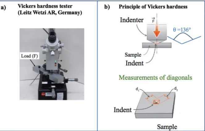
3.3.1. Vickers hardness ... 51
3.3.2. Indentation fracture resistance (KIIFR) ... 51
3.3.3. Elastic modulus and flexural strength ... 51
3.3.4. Tribological Properties ... 51
3.3.5. Coefficient of friction and wear rate ... 52
4. Monolithic Si3N4 systems ... 54
4.1. Starting powders ... 54
4.1.1. Oxidation process of starting powders ... 54
4.1.2. Sintering aids ... 55
4.1.3. Milling process ... 55
4.1.4. Fabrication of green samples ... 56
4.1.5. Densification of powders by hot isostatic pressing (HIP) ... 56
4.2. Investigation of starting powders... 58
4.3. Investigation of sintered samples ... 62
4.3.1. Structural investigation ... 62
4.3.2. Mechanism of in-situ growth of Si2N2O and α- to β- Si3N4 transformation ... 63
4.4. Mechanical properties ... 66
4.4.1. Vickers hardness ... 66
4.4.2. Flexural Strength ... 67
4.4.3. Young’s Modulus ... 69
4.4.4. Indentation fracture resistance (KIIFR) ... 70
4.4.5. Fractographic analysis of sintered samples ... 71
4.5. Tribological Properties ... 72
4.5.1. Coefficient of friction (COF) ... 72
4.5.2. Wear rate ... 74
4.5.3. Wear Mechanism ... 76
5. Si3N4 + 3 wt% MWCNTs composites... 80
5.1. Preparation of Si3N4 + 3 wt% MWCNTs composites by HIP ... 80
5.1.1. Starting powders ... 80
5.1.2. Sintering aids ... 80
5.1.3. Milling process ... 80
5.1.4. Fabrication of green samples ... 81
5.1.5. Densification of powders by hot isostatic pressing (HIP) ... 81
5.2. Investigation of starting powders... 82
5.2.1. Structural investigation ... 82
5.2.2. Microstructural analysis of starting powders ... 83
5.3. Investigation of sintered samples ... 84
5.3.1. Structural investigation ... 84
5.3.2. Apparent Density ... 85
5.4. Mechanical properties ... 85
5.4.1. Vickers hardness ... 85
5.4.2. Flexural Strength ... 86
5.4.3. Young’s Modulus ... 87
5.4.4. Fractographic analysis of fractured surfaces ... 88
5.5. Tribological properties... 89
5.5.1. Coefficient of friction (COF) ... 89
5.5.2. Wear Rate ... 90
6. Si3N4 + 1 wt% graphene composites ... 91
6.1. Preparation of Si3N4 + 1 wt% graphene composites ... 91
6.2. Investigation of starting powders... 92
6.2.1. Microstructural analysis ... 92
6.3. Investigation of sintered samples ... 93
6.3.1. Apparent density ... 93
6.4. Mechanical Properties ... 94
6.4.1. Micro Vickers Hardness ... 94
6.4.2. Indentation fracture resistance (KIIFR) ... 95
6.4.3. Fractographic analysis ... 95
6.5. Tribological Properties ... 96
6.5.1. Coefficient of friction (COF) ... 96
6.5.2. Wear rate ... 97
6.5.3. Wear Mechanism ... 98
7. Conclusion ... 101
7.1. Further challenges ... 106
8. Publications... 108
8.1. Publications related to PhD topic ... 108
8.2. Other publications ... 109
8.3. PhD work presentation in conferences ... 109
8.4. Scientific Impact of my research ... 111
9. Reference ... 112
List of Symbols and Abbreviations
α Alpha
β Beta
CCVD Catalytic chemical vapor deposition
CNTs Carbon nanotubes
COF Coefficient of friction
EDX Energy dispersive X-ray
GNPs Graphene nanoparticles
GO Graphene oxide
GPa Giga Pascal
GPLs Graphene platelets
GPS Gas pressure sintering
HIP Hot isostatic pressing
HP Hot pressing
HRTEM High resolution transmission electron microscopy
HV Vickers Hardness
KIC Fracture toughness
KIIFR Indentation fracture resistance
MPa Mega Pascal
MWCNTs Multi-walled carbon nanotubes
PEG Polyethylene glycol
rGO Reduced graphene oxide
ρs Apparent Density
SEM Scanning electron microscopy SEPB Single edge pre-cracked beam
SEVNB Single-edge-V-notched beam
Si3N4 Silicon nitride Si2N2O Silicon oxynitride
SPS Spark plasma sintering
SWCNTs Single-walled carbon nanotubes TEM Transmission electron microscopy UMT Universal Mechanical Tester
XRD X-ray Diffraction
1. Introduction and objectives of the work
In 1859, Sainte-Claire Deville and F. Wohler reported the synthesis of Si3N4 for the first time by [1]. In 1955, J. F. Collins and R. W. Gerby found that silicon nitride-based ceramics have potential thermal and mechanical properties at high temperatures [2]. Simultaneously, the silicon nitride was not developed fully dense until then, and it was fabricated by a reaction bonding method only. In the 1960s, Deeley et al. [3] developed, for the first time, highly dense silicon nitride materials with sintering additives by hot pressing (HP). In the early 1970s, researchers focused on silicon nitride-based ceramics for gas turbine application [4].
Later on, different sintering techniques were developed, such as pressureless sintering [5] and gas pressure sintering (GPS) [6] which made it possible to produce complex-shaped components with high density. Silicon nitride is considered a structural ceramic material with several excellent properties such as excellent flexural strength, fracture resistance, high hardness, oxidation resistance, thermal properties at the room, and elevated temperatures.
Despite having unique properties, silicon nitride also exhibits some negative properties, such as brittleness, low flaw tolerance, limited-slip systems, and low reliability, limiting its broader applications. To overcome such flaws, the addition of reinforcement in the silicon nitride matrix was proposed.
Another problem is the formation of amorphous glassy phases at grain boundaries of sintered silicon nitride. Due to covalent bonds and low solid-state diffusion in Si3N4, sintering is very difficult. Oxide additives such as Y2O3, Al2O3, CaO, MgO, etc., are used to provide conditions for liquid phase sintering of this ceramic material. These additives create liquid phases that enhance silicon nitride's densification and its transformation from the α-Si3N4 to the β-Si3N4 (Jack, 1976). Upon cooling, these liquid phases appear in the grain boundaries or at triple points of silicon nitride as amorphous oxide glasses. These glassy phases are detrimental to the mechanical properties of sintered silicon nitride at high temperatures. The glassy phases become soften at grain boundaries at a temperature above 1000 °C and affect the mechanical properties. These glassy phases are needed to eliminate or convert from amorphous to a crystalline phase which could play a role in improving properties at high temperature.
Many researchers developed silicon nitride with different reinforcements and achieved success to some extent. With the discovery of carbon nanotubes (CNTs) in 1991 and graphene in 2004, a new research horizon arose in the materials science field. Since their discoveries,
carbon nanofillers are being exploited to improve the mechanical, tribological, and electrical properties of advanced ceramics, including silicon nitride. The carbon nanofillers are promising candidates as reinforcements in the silicon nitride matrix to improve the composite properties.
Therefore, researchers utilize different carbon nanofillers with varying concentrations, adopting various milling methods and parameters and applying different sintering techniques with varying parameters to explore the mechanical, tribological, thermal, and functional properties of silicon nitride composites. The carbon nanofillers are not exploited well yet;
there is still a need for much more focused research to exploit the nanofillers as reinforcement to improve silicon nitride's several properties.
The current work proposed that glassy phases might be eliminated or converted from amorphous to glassy phases by surface oxidation of silicon nitride’s starting powders at high temperatures. The current work is also a contribution towards the exploration of silicon nitride's mechanical and tribological properties with the addition of carbon nanofillers. In this work, different techniques and parameters were adopted to optimize and obtain better results.
The objectives of the current work are:
• To develop silicon nitride materials without glassy phases at the grain boundaries
• To study the effect of oxidation of starting powders on structural, mechanical, and tribological properties of sintered silicon nitride.
• To develop MWCNTs reinforced silicon nitride composites processed from oxidized α-Si3N4 powders and to study their mechanical and tribological properties.
• To investigate the microstructure of starting powders by scanning electron microscopy (SEM), transmission electron microscopy (TEM), and high-resolution transmission electron microscopy (HRTEM), and phases analysis by X-ray diffraction (XRD) technique.
The thesis work mainly consists of two parts – the theoretical part, which describes the literature, and the practical part, which illustrates the author’s work about the development of composites, their testing, and results. Chapter 1 describes a brief history of the development of silicon nitride and the problem and presents the main aims of the current work. Chapter 2 is devoted to the theoretical background and literature review of silicon nitride and carbon nanofillers. It presents processing techniques, mechanical, tribological properties, and testing methods of silicon nitride-based composites. Chapter 3 describes the experimental program, characterization techniques, and testing methods that were used for the current work. Chapter
4 is the start of the experimental part of the thesis, and it deals with the development of monolithic silicon nitride systems. The chapter starts with the detailed method of oxidation of starting powders, preparation of composites, characterization of starting powders and sintered samples, mechanical properties, and tribological properties to identify wear mechanism.
Chapter 5 focuses on the preparation of MWCNTs reinforced Si3N4 composites, their mechanical and tribological properties. Chapter 6 presents the brief results and discussions on graphene reinforced silicon nitride composites. Due to the limited time for this project, only the composites' tribological properties were done, and my colleagues have already published the other presented results. Chapter 7 consists of a conclusion and the further challenges in developing silicon nitride composites with carbon nanofillers, which may help researchers in this field. Chapter 8 comprises publications, conferences, and the impact of research. Chapter 9 ends with the references used in this thesis work.
2. Theoretical Background and Literature Review
2.1. Advanced ceramic materials
In general, ceramics are non-metals that are hard, brittle, and heat resistant. Many definitions of ceramics are available in the literature. But most widely accepted definition of ceramics is presented by Kingery et al. [7]. According to them, the definition of ceramic is “a ceramic is non-metallic, inorganic solid.” Based on production methods, properties, and application of ceramics, they can be classified into further classes (Figure 2.1):
1. traditional ceramics, 2. advanced ceramics.
Traditional ceramics are composed of clay minerals (e.g., porcelain, bricks, tiles, toilet bowls, and pottery), and they possess high hardness, extreme brittleness, and very susceptible to fracture. Advanced ceramics are also inorganic and non-metallic, but their microstructure is highly engineered to reflect its impact on ceramics' final mechanical properties. Grain size, grain shape, porosity, and phase compositions are carefully engineered to enhance the product's properties. Advanced ceramics are also called engineering ceramics, technical ceramics, structural ceramics, or special ceramics. Traditional ceramics have been using since the stone age, and advanced ceramics have been developed within the last 100 years.
Ceramics is a multibillion dollars industry, and 17% of the sector is occupied by advanced ceramics [8].
Figure 2.1 - Classification of ceramics based on processing and applications. The current work focuses on Si3N4 based ceramics which lie in the advanced ceramics class (highlighted by green circle) Author’s work.
The advanced ceramics can be classified further based on their chemical composition (Figure 2.1.). Here, a brief introduction about the classified advanced ceramics will be presented, and the focus will be on Si3N4 based ceramics in the following chapters.
1. Oxide ceramics: these ceramics materials are based on metals or metalloids elements combined with oxygen—for example, Al2O3, ZrO2, TiO2, and Y2O3.
2. Nitride ceramics: nitride ceramics are a class of ceramics based on nitrogen combined with other elements—for instance, Si3N4, SiAlON, TiN, AlN.
3. Carbide ceramics: These are based on carbides, and SiC is one of the most important and widely used ceramic materials. e.g., SiC, B4C, WC, TiC, NbC.
4. Boride Ceramics: Boride ceramics are a class of ceramics that have boron as one of the essential elements combined with rare earth elements or transition metals such as LaB6, TiB2, ZrB2, HfB2.
2.1.1. Silicon nitride (Si3N4)
Silicon nitride (Si3N4) is classified as an advanced structural ceramic with a high melting point, high hardness, and is relatively chemically inert. Si3N4 is the stoichiometric compound in the Si–N binary system [9]. Other silicon nitrides (Si2N3 [10], SiN [11], Si3N [12], Si(N3)4) in this Si–N binary system have been reported, but their existence was considered doubtful.
The calculated phase diagram of the Si–N system is given in Figure 2.2.
Figure 2.2 - Calculated phase diagram of Si-N system based on [9].
Si3N4 has three crystallographic structures at room temperature, which are named as α, β and ϒ. α and β are the most common crystallographic phases of silicon nitride and have
technological applications in advanced ceramics [13] [14]. Every crystallographic structure has its own characteristics whose presence influences the final properties of the silicon nitride composite. The ϒ phase of silicon nitride has a cubic structure, and therefore it is the hardest phase, with a value of up to 35 GPa, and is not widely used for structural applications [14][15]. The β phase has an elongated hexagonal structure and high toughness. The α phase has a trigonal structure and is harder than the β phase [15].
Silicon nitride-based materials have been used as cutting tools, bearings, sealings, parts of gas turbines, engines, etc., due to their exceptional combination of mechanical properties as flexural strength, hardness, resistance to oxidation, tribological and thermal properties [16]–
[22].
2.2. Carbon-based nanostructures
The era of carbon nanostructure started with the discovery of fullerenes (C60) in 1985 [23]
[24]. Later, discoveries of carbon nanotubes (CNTs) by Ijima [25] and graphene by Geim and Novoselov [26] strengthened further development in carbon nanotechnology. Due to the importance, the discovery of two (fullerenes, graphene) of the carbon nanostructures got Nobel prizes. A new horizon of research opened up, and the properties of carbon nanostructures were exploited to develop novel materials in the last two decades.
Based on structure, carbon nanostructures can be divided into further types, as illustrated in Figure 2.3:
1. Fullerene,
2. Carbon nanotubes (CNTs), 3. Graphene,
4. Diamond-like carbon.
Here, only carbon nanotubes and graphene will be discussed.
Figure 2.3 - Type of carbon-based nanostructures and classified based on sp-hybridization and 0D to 3D [23].
2.2.1. Carbon nanotubes
During the production of carbon C60 and fullerene by arc evaporation of graphite, Ijima examined the deposited carbon layer on the graphite by a high-resolution transmission electron microscope (HRTEM) [25]. He discovered a new form of carbon, which consisted of a graphene cylindrical tube with 10 nm diameter, and the end-cap was like a fullerene structure. This new form of carbon was named a carbon nanotube (CNT) based on its physical appearance. A CNT has three basic orientations (Figure 2.4) [27]:
Armchair orientation: Graphene cylinder along a five-fold axis with a fullerene-like cap at the end (Figure 2.4-a).
Zigzag orientation: Graphene cylinder along a three-fold axis with a fullerene-like cap at the end (Figure 2.4-b).
Chiral orientation: Graphene cylinder along with a helical arrangement with a fullerene- like cap at the end (Figure 2.4-c).
Carbon nanotubes (CNTs) are classified into two groups: multi-walled carbon nanotubes (MWCNTs) and single-walled carbon nanotubes (SWCNTs) [28]. MWCNTs consist of multiple concentric graphene cylinders, while SWCNTs comprise a single layer of a graphene cylinder. The diameter of CNT ranges between 1 and 50 nm, and the length ranges from a few nm to a few µm [29][30][31][32]. A CNT has a tensile strength 10 times greater than that of steel, and its stiffness is 15 times higher than that of steel (Table 2.1). The comparison of the properties of different materials is given in Table 2.1.
Table 2.1 - Comparison of properties of CNT and other materials. Reproduced from [33]
Material Density (g/cm3) Tensile Strength (GPa) Stiffness (GPa)
CNTs 1.3–2 10–60 1000
Wood 0.6 0.008 16
Steel 7.8 0.4 208
Carbon Fiber 1.7–2.2 1.7–3.3 200–960
Epoxy 1.25 0.005 3.5
Figure 2.4 - Three types of carbon nanotubes (CNTs): (a) armchair (n, m) = (5, 5); (b) zigzag (n, m) = (9, 0); (c) chiral (n, m) = (10, 5) [27].
CNTs can be produced in two main ways:
(i) Arc Evaporation Method: A 50 Ampere current is applied between graphite electrodes to evaporate the graphite, and this is done in a helium environment. CNTs are condensed at the cathode. Ijima also used this method to produce CNTs [25]. This method can produce SWCNTs with the addition of Ni and Co at graphite anode electrode [33].
(ii) Catalytic Method: CNTs are produced by the decomposition of hydrocarbons over the metallic catalysts (Fe, Co, Ni) [34][35]. This method has the one disadvantage that CNTs are produced with lattice defects more than that of the arc evaporation method. These defects can be reduced by heat treatment after production [36].
2.2.2. Graphene
Graphene is a 2D single and thin layer of graphite with sp2 hybridization arranged in hexagons. Graphite is an allotrope of carbon; graphite and graphene contain the same atoms, but a different arrangement of atoms gives different properties. In 2004, Andre Geim and Konstantin Novoselov discovered graphene by using scotch tape to polish a large block of graphite; the researchers spotted very thin flakes on the tape [37]. They continuously peeled layer by layer from the flakes of graphite and fabricated a thin sample layer as a single layer of graphite, which is now called graphene. The structure of graphene is illustrated in Figure 2.5.
Figure 2.5 - Honeycomb lattice of graphene. Graphene layers can be stacked into graphite or rolled up into carbon nanotubes [38].
Due to the strength of its carbon bonds, graphene is the strongest material, with a tensile strength of 130 GPa and Young's modulus close to 1 TPa [39] [40]. The Class for Physics of the Royal Swedish Academy of Sciences enlightened in their Nobel Prize announcement that a 1 m2 graphene hammock would support a cat of 4 kg but would weigh only as much as one of the cat's whiskers, at 0.77 mg, which is about 0.001% of the weight of 1 m2 of a paper [41].
They also illustrated that graphene is more than 100 times stronger than the strongest steel [41].
2.3. Silicon nitride-based composites with carbon nanofillers reinforcement
To enhance the properties, several studies have been done on the carbon nanofillers reinforced silicon nitride composites. To some extent, the addition of carbon nanostructures was useful to enhance the mechanical, tribological, and electrical properties. The use of carbon nanostructures has not been exploited well because of the challenges in integrating nanostructures in the silicon nitride matrix. The main problems are non-uniform dispersion of reinforcement, incomplete densification, and porosity induced by the nanostructures. There is still a need to work done to address such problems.
However, Si3N4 is a structural ceramic material with many excellent properties, but at the same time, it has some negative properties which limit its applications in many sectors. The negative properties are brittleness, low flaw tolerance, and limited-slip systems. To overcome these negative characteristics, researchers proposed an idea to develop a composite by combining the properties of two or more constituents by adding a second phase to the silicon nitride matrix. The second phase should have such properties whose combination could give an optimum property. An improvement was achieved to some extent, but many challenges came up as well. Different silicon nitride-based composites have been developed with fine- grained matrix and ex-situ or in-situ introduced elongated β-Si3N4 grains [42]–[45].
One of the positive effects is the toughening mechanism induced by the CNTs and graphene.
Several researchers reported the enhancement of fracture toughness of the composite with the addition of carbon nanotubes and graphene than that of monolithic material [46]–[49] [50]–
[52].
Pasupuleti et al. [46] prepared 1 wt% CNTs reinforced Si3N4 composites by hot pressing (HP) technique. They reported an increase in fracture toughness with the addition of CNTs, which is because of the toughening mechanism by crack-bridging and pulling-out effect of CNTs.
Moreover, R-curve behavior increased with the addition of CNTs, which enhance the composite's toughening behavior. So far, Matsuoka et al. [47] have also reported the highest value of fracture toughness (8.6 MPa·m1/2) of 1 wt% MWCNT-reinforced silicon nitride composite.
But some researchers also reported a decrease in fracture toughness of silicon nitride with the addition of CNTs [53][54]. Kovalcıkova et al. [53] reported a decrease in hardness and toughness of silicon nitride composite due to the high level of porosity, which was induced by the addition of MWCNTs.
Walker et al. [51] developed a uniform and homogeneously dispersed graphene platelets (GPLs) reinforced silicon nitride composites by spark plasma sintering. The reported significant increase in fracture toughness with a value of 6.6 MPa.m1/2 for 1.5 vol% GPLs reinforced Si3N4 than that of monolithic silicon nitride material. The increase in fracture toughness is attributed to the toughening mechanisms in the form of graphene necking, crack bridging, crack deflection, and pull-out. The observed toughening mechanisms by graphene platelets are evidenced by SEM image (Figure 2.6)
Figure 2.6 - Toughening mechanisms in GPL-Si3N4 nanocomposites. (a) Microhardness testing resulting in the creation of radial cracks stemming from the microhardness indent.
Closer examination of the radial cracks reveals GPL bridging the crack at several locations, two of which are shown in this high-resolution SEM image. (b) Further examination of the
radial cracks indicates that they follow a tortuous crack propagation path. (c) Fracture surface of the bulk sample indicates the presence of three-dimensional toughening
mechanisms for the GPL-Si3N4 nanocomposite [51].
Despite the positive effect of carbon nanostructures' addition, several challenges have to be dealt such as preservation of reinforcements, interfacial bonding between matrix and reinforcements, uniform dispersion, load transferability, and amount of reinforcement.
Effective load transfer plays a role in enhancing the toughness, and it depends on the interfacial strength between CNTs and silicon nitride grains. Without the optimum interfacial strength, the effective load transfer is not possible, which leads to the diminishing of crack- bridging and pulling-out mechanisms on the fracture surface.
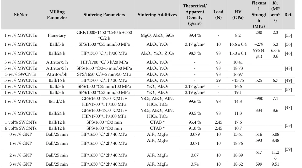
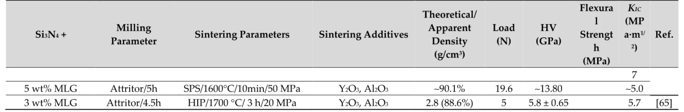
It is difficult to compare the influence of graphene and CNTs on the properties of Si3N4-based composites because of limited and ambiguous results reported in the literature. Tables 2.2 and 2.3 comprise the effect of CNT/graphene on the mechanical and tribological properties of silicon nitride. Only selected results from the literature have been presented in tables 2.2 and 2.3. Both CNTs and Graphene are promising candidates to enhance ceramics' mechanical, tribological, and functional properties.
Table 2.2 – Mechanical properties of carbon nanofillers reinforced silicon nitride with processing parameters from literature.
Si3N4 + Milling
Parameter Sintering Parameters Sintering Additives
Theoretical/
Apparent Density
(g/cm3)
Load (N)
HV (GPa)
Flexura l Strengt
h (MPa)
KIC (MP a·m1/
2)
Ref.
1 wt% MWCNTs Planetary GRF/1000~1450 °C/40 h + 550
°C/2 h MgO, Al2O3, SiO2 89.4 % - 8.2 280 2.3
[55]
1 wt% MWCNTs Ball/3 h SPS/1500 °C/5 min/50 MPa Al2O3, Y2O3 3.17 g/cm3 10 16.6 ± 0.4 ∼279 5.3 [56]
1 wt% MWCNTs Ball/24 h HP/1750 °C /1 h/30 MPa Al2O3, Y2O3, ZrO2 98.7 % 98 15.0 ± 0.1 996 (4 pt.)
6.6 ± 0.6 [46]
3 wt% MWCNTs Attritor/5 h HIP/1700 °C/ 3 h/20 MPa Al2O3, Y2O3 - 98 10.41
[48]
3 wt% MWCNTs Attritor/5 h SPS/1650 °C/3–5 min/50 MPa Al2O3, Y2O3 - 98 18.73 3 wt% SWCNTs Attritor/5h SPS/1650°C/3–5 min/50 MPa Al2O3, Y2O3 - 98 16.97
5 wt% MWCNTs Ball/16 h HP/1700 °C/1 h/ 30 MPa Al2O3, Y2O3 - 29 ∼13.75 525 6.7 [49]
1 wt% MWCNTs Ball/3 h SPS/1500 °C/5 min/100 MPa Y2O3, Al2O3 3.17 g/cm3 - 16.6
[57]
1 wt% MWCNTs Ball/3 h SPS/1500 °C/3 min/50 MPa Y2O3, Al2O3 3.19 g/cm3 - 19.1 1 wt% MWCNTs Bead/2 h GPS/1600–1750 °C/2 h +
HIP/1700°/1 h/100 MPa
Y2O3, Al2O3, AlN.
HfO2, TiO2 99.6 % 98 14.8 ∼980 7.1
[47]
1 wt% MWCNTs Ball/24 h GPS/1600–1750 °C/2 h +
HIP/1700°/1 h/100 MPa Y2O3, Al2O3, AlN.
HfO2, TiO2 93.5 % 98 11.3 834 8.6
1 vol% SWCNTs Ball/12 h SPS/1600 °C/3 min CTAB * 95.4 % 2.45 17.6
[58]
6 vol% SWCNTs Ball/12 h SPS/1600 °C/3 min CTAB * 91.0 % 2.45 10.7
0 wt% GNP Ball/25 min HP/1650 °C/ 2h/ 40 MPa AlF3, MgF2 3.079 10 15.61 516 5.08
[59]
1 wt% GNP Ball/25 min HP/1650 °C/ 2h/ 40 MPa AlF3, MgF2
3.071 10 18.76 593 8.48
2 wt% GNP Ball/25 min HP/1650 °C/ 2h/ 40 MPa AlF3, MgF2 3.07 10 18.89 617 11.2 6 3 wt% GNP Ball/25 min HP/1650 °C/ 2h/ 40 MPa AlF3, MgF2 3.74 10 18.62 599 9.51
Si3N4 + Milling
Parameter Sintering Parameters Sintering Additives
Theoretical/
Apparent Density
(g/cm3)
Load (N)
HV (GPa)
Flexura l Strengt
h (MPa)
KIC
(MP a·m1/
2)
Ref.
0 wt% rGO Ball/2h h HP/ 1700°C/1h/30MPa Y2O3, Al2O3 99.79 196 16.6 608 6.17 [60]
0.75 wt% rGO Ball/2h h HP/ 1700°C/1h/30MPa Y2O3, Al2O3 99.92 196 18.6 784 7.63 1.50 wt% rGO Ball/2h h HP/ 1700°C/1h/30MPa Y2O3, Al2O3 99.51 196 17.9 962 9.26 2.25 wt% rGO Ball/2h h HP/ 1700°C/1h/30MPa Y2O3, Al2O3 99.06 196 17.3 1116.4 10.3 0 wt% GNP Ball mill/- SPS/1700°C/10 min/vacuum Y2O3, Al2O3 3.31 98 17.5 - 5.1
[61]
3 wt% GNP Ball mill/- SPS/1700°C/10 min/vacuum Y2O3, Al2O3 3.27 98 13.5 - 6.6 5 wt% GNP Ball mill/- SPS/1700°C/10 min/vacuum Y2O3, Al2O3 3.21 98 12.8 - 7.5 3 wt% FL-GNP Ball mill/- SPS/1700°C/10 min/vacuum Y2O3, Al2O3 3.29 98 13.7 - 10.5 5 wt% FL-GNP Ball mill/- SPS/1700°C/10 min/vacuum Y2O3, Al2O3 3.29 98 9.8 - 7.6
0 vol% GNP Ball mill/2h SPS/1700°C/10 min/vacuum Y2O3, Al2O3 3.23 9.8 20.4 ∼950 ∼4.5 [62]
4.3 vol% GNP Ball/2h SPS/1625°C/5 min/50 MPa Y2O3, Al2O3 3.18 9.8 17.7 ∼925 ∼6.5 7.2 vol% GNP Ball/2h SPS/1625°C/5 min/50 MPa Y2O3, Al2O3 3.16 9.8 16.4 - ∼5.5 4.3 vol% rGO Ball/2h SPS/1625°C/5 min/50 MPa Y2O3, Al2O3 3.19 9.8 15.9 ∼1040 ∼10 7.2 vol% rGO Ball/2h SPS/1625°C/5 min/50 MPa Y2O3, Al2O3 3.16 9.8 14.6 - ∼9.2 0 wt% Attritor/5h SPS/1600°C/10 min/50 MPa Y2O3, Al2O3 ∼98.2% 19.6 17.5 - 5.4
[63]
1 wt% MLG Attritor/5h SPS/1600°C/10 min/50 MPa Y2O3, Al2O3 ∼97.60 19.6 18.4 - 4.4 3 wt% MLG Attritor/5h SPS/1600°C/10 min/50 MPa Y2O3, Al2O3 ∼97.25 19.6 15.2 - 4.9 5 wt% MLG Attritor/5h SPS/1600°C/10 min/50 MPa Y2O3, Al2O3 ∼97.09 19.6 13.7 - 5.4
0 wt% GPLs Ball/12h HP/1750°C/1h/20 MPa Y2O3, Al2O3, MgO 3.1 296 5.32
[52]
0.2 wt% GPLs Ball/12h HP/1750°C/1h/20 MPa Y2O3, Al2O3, MgO 3.14 305 5.86
2 wt% GPLs Ball/12h HP/1750°C/1h/20 MPa Y2O3, Al2O3, MgO 3.06 270 1.87
0 wt% MLG Attritor/5h SPS/1600°C/10min/50 MPa Y2O3, Al2O3 ∼98% 19.6 ∼17.5 ∼5.3 [64]
1 wt% MLG Attritor/5h SPS/1600°C/10min/50 MPa Y2O3, Al2O3 ∼96.5% 19.6 ∼18.37 ∼4.8 3 wt% MLG Attritor/5h SPS/1600°C/10min/50 MPa Y2O3, Al2O3 ∼93.8% 19.6 ∼15.25 ∼4.8
Si3N4 + Milling
Parameter Sintering Parameters Sintering Additives
Theoretical/
Apparent Density
(g/cm3)
Load (N)
HV (GPa)
Flexura l Strengt
h (MPa)
KIC
(MP a·m1/
2)
Ref.
7 5 wt% MLG Attritor/5h SPS/1600°C/10min/50 MPa Y2O3, Al2O3 ∼90.1% 19.6 ∼13.80 ∼5.0 3 wt% MLG Attritor/4.5h HIP/1700 °C/ 3 h/20 MPa Y2O3, Al2O3 2.8 (88.6%) 5 5.8 ± 0.65 5.7 [65]
Table 2.3 – Tribological properties of carbon nanofillers reinforced silicon nitride with the processing parameters from literature.
Si3N4 + Milling Parameter
Sintering Parameters Sintering Additives
Theoretical/Apparent Density (g/cm3)
Load (N)
Test Conditions
Wear rate Ref.
0 wt% MWCNTs Attritor/5h HIP/1700°C/3h/20 MPa Y2O3, Al2O3 - 5 Dry ∼ 1.10 x 10⁻⁵ [66]
1 wt% MWCNTs Attritor/5h HIP/1700°C/3h/20 MPa Y2O3, Al2O3 - 5 Dry ∼ 2.0 x 10⁻⁵ 3 wt% MWCNTs Attritor/5h HIP/1700°C/3h/20 MPa Y2O3, Al2O3 - 5 Dry ∼ 4.9 x 10⁻⁵ 5 wt% MWCNTs Attritor/5h HIP/1700°C/3h/20 MPa Y2O3, Al2O3 - 5 Dry ∼ 1.10 x 10⁻⁵ 10 wt% MWCNTs Attritor/5h HIP/1700°C/3h/20 MPa Y2O3, Al2O3 - 5 Dry ∼ 8.0 x 10⁻⁵ 0 vol% MWCNTs Ultrasonic
stir
SPS/1585°C/5min/50 MPa Y2O3, Al2O3 3.23 50 Isooctane lubricant
∼ 0.61 x 10⁻⁶ [67]
1.8 vol%
MWCNTs Ultrasonic
stir
SPS/1585°C/5min/50 MPa Y2O3, Al2O3 3.20 50 Isooctane lubricant
∼ 0.47 x 10⁻⁶ 5.3 vol%
MWCNTs Ultrasonic
stir
SPS/1585°C/5min/50 MPa Y2O3, Al2O3 3.15 50 Isooctane lubricant
∼ 0.33 x 10⁻⁶ 8.6 vol%
MWCNTs
Ultrasonic stir
SPS/1585°C/5min/50 MPa Y2O3, Al2O3 3.12 50 Isooctane lubricant
∼ 0.16 x 10⁻⁶
0 wt% MWCNTs Attritor/5h HIP/1700°C/3h/20 MPa Y2O3, Al2O3 - 5 Dry ∼ 3.02 x 10⁻⁶ [68]
3 wt% MWCNTs Attritor/5h HIP/1700°C/3h/20 MPa Y2O3, Al2O3 - 5 Dry ∼ 3.34 x 10⁻⁷
0 wt% MWCNTs Attritor/5h HIP/1700°C/3h/20 MPa Y2O3, Al2O3 - 5 Dry ∼ 1.8 x 10⁻⁷ [69]
Si3N4 + Milling Parameter
Sintering Parameters Sintering Additives
Theoretical/Apparent Density (g/cm3)
Load (N)
Test Conditions
Wear rate Ref.
1 wt% MWCNTs Attritor/5h HIP/1700°C/3h/20 MPa Y2O3, Al2O3 - 5 Dry ∼ 3.5 x 10⁻⁵ 3 wt% MWCNTs Attritor/5h HIP/1700°C/3h/20 MPa Y2O3, Al2O3 - 5 Dry ∼ 0.9 x 10⁻⁵ 10 wt% MWCNTs Attritor/5h HIP/1700°C/3h/20 MPa Y2O3, Al2O3 - 5 Dry ∼ 8.05 x 10⁻⁵
0 wt% GNP Attritor/5h SPS/1700°C/10min Y2O3, Al2O3 3.32 5 Dry ∼ 1.2 x 10⁻⁵ [70]
3 wt% GNP Attritor/5h SPS/1700°C/10min Y2O3, Al2O3 3.28 5 Dry ∼ 9.8 x 10⁻⁶ 3 wt% FL-GNP Attritor/5h SPS/1700°C/10min Y2O3, Al2O3 3.3 5 Dry ∼ 6.5 x 10⁻⁶ 5 wt% FL-GNP Attritor/5h SPS/1700°C/10min Y2O3, Al2O3 3.13 5 Dry ∼ 2.1 x 10⁻⁷ 0 wt% GNP Ball/2h SPS/1625°C/5min/50 MPa Y2O3, Al2O3 3.23 50 Isooctane
lubricant ∼ 6.94 x 10⁻⁸ [71]
3 wt% GNP Ball/2h SPS/1625°C/5min/50 MPa Y2O3, Al2O3 3.18 50 Isooctane
lubricant ∼ 5.83 x 10⁻⁸ 0 wt% GNP Ball/2h SPS/1625°C/5min/50 MPa Y2O3, Al2O3 3.23 100 Isooctane
lubricant ∼ 5.0 x 10⁻⁸ 3 wt% GNP Ball/2h SPS/1625°C/5min/50 MPa Y2O3, Al2O3 3.18 100 Isooctane
lubricant ∼ 3.33 x 10⁻⁸ 0 wt% GNP Ball/2h SPS/1625°C/5min/50 MPa Y2O3, Al2O3 3.23 200 Isooctane
lubricant ∼ 4.86 x 10⁻⁸ 3 wt% GNP Ball/2h SPS/1625°C/5min/50 MPa Y2O3, Al2O3 3.18 200 Isooctane
lubricant ∼ 2.06 x 10⁻⁸
0 wt% MLG Attritor/5h HIP/1625°C/3h/20 MPa Y2O3, Al2O3 - 5 Dry ∼ 7.5 x 10⁻⁶ [72]
1 wt% MLG Attritor/5h HIP/1625°C/3h/20 MPa Y2O3, Al2O3 - 5 Dry ∼ 7.0 x 10⁻⁶ 3 wt% MLG Attritor/5h HIP/1625°C/3h/20 MPa Y2O3, Al2O3 - 5 Dry ∼ 2.4 x 10⁻⁵
2.3.1. Effect of carbon nanofillers on hardness
The effect of CNTs and graphene on silicon nitride composites' microhardness is not positive as the positive effect on fracture toughness, electrical and tribological properties. According to the results, the hardness values are in a strong relationship with the values of densities. Due to the tendency of agglomeration of CNTs and graphene, the porosity of silicon nitride-based composites increased. Balazsi et al. [73] reported decreased Vickers hardness of silicon nitride composites with increasing amount of multi-layered graphene (MLG). The hardness increased with the addition of 1 wt% MLG and then started decreasing with the higher amount of MLG. The decrease in Vickers hardness attributed to the soften-carbon parts and high porosity because of the addition of MLG. Similarly, in CNTs added silicon nitride, the decreasing tendency in microhardness has been observed. More study is needed to understand the negative phenomenon of carbon nanofillers on the hardness of silicon nitride.
Recently, Hu et al. [60] reported the addition of reduced graphene (rGO) sheets to Si3N4 results in superior mechanical properties to a monolithic Si3N4. They prepared a novel reduced graphene oxide‐encapsulated silicon nitride (Si3N4@rGO) particle via electrostatic interaction between amino‐functionalized Si3N4 particles and graphene oxide (GO). The improvement in Vickers hardness is attributed to the refined microstructure of the composites.
The addition of rGO leads to microstructure refinement, which increased the hardness by hindering the silicon nitride grains' dislocation.
2.3.2. Effect of carbon nanofillers on flexural strength
The flexural strength of CNTs and graphene added silicon nitride composites is comparable with the strength of the monolithic material. No significant improvement in flexural strength has been reported so far. Technological and surface defects such as clusters of reinforcements, impurities, pores, and non-densified areas cause the fracture origin. In service under loads, these defects serve as a fracture origin and decrease the strength as per their character, size, and location in the microstructure.
But some studies found a slight improvement in flexural strength, but the reason behind the improvement is still not clear. Balazsi et al. [57] developed the silicon nitride composite with 1 wt% of MWCNTs, and the bending strength was found to be higher than that of silicon nitride without MWCNTs. By pulling out, the MWCNTs’ strengthening mechanism was observed in the composite [57]. Yoshio et al. [74] reported that bead milling results in well-
pulverized agglomerates of CNTs, uniformly dispersed in ethanol, and prepared Si3N4 + CNT ceramics in such a way, and the bending strength was improved.
Hu et al. [60] reported 83.5% increased flexural strength and reached a maximum value of 1116.4 MPa, and the fracture toughness increased by 67.7% to 10.35 MPa·m1/2 with the addition of 2,25 wt% rGO as reinforcement in the silicon nitride matrix.
2.3.3. Effect of carbon nanofillers on tribological properties
The carbon nanostructures have attracted much attention to be used as self-lubricating nanofillers in silicon nitride composites working under severe friction and wear conditions.
The tribological study of graphene added ceramics started in 2013 after the publication by Hvizdos et al. [72] and Belmonte et al. [71]. Hvizdos et al. [72] studied mechanical and tribological properties of nanocomposites with silicon nitride matrix with the addition of 1 and 3 wt% of various types of graphene platelets. They observed that 1 wt% graphene phase does not lower the coefficient of friction in dry conditions but, 3 wt% of larger sized graphene reinforced showed higher wear resistance. Belmonte et al. [71] investigated the tribological properties of graphene nanoplatelets (GNPs)/Si3N4 composites using a reciprocating ball-on- plate configuration under isooctane lubrication. They observed that exfoliated graphene nanoplatelets formed an adhered protective tribofilm, which acted as lubrication and enhanced up to 56% wear resistance.
Similarly, CNTs are also beneficial to enhance the tribological properties of silicon nitride composites. Gonzalez-Julian et al. [67] found the better tribological properties in terms of low wear rate with the addition of 8.6 vol% MWCNT in silicon nitride matrix than the monolithic Si3N4 ceramics under the load of 50 N in isooctane lubrication condition. The improved wear properties were attributed to the homogeneous dispersion of CNTs and the extra effect of lubrication by CNTs. It was observed that Si3N4 + MWCNT composites showed 40% lower friction coefficient and 80% lower wear rates than that of the monolithic silicon nitride materials.
Balko et al. [69] prepared the silicon nitride composite with 1, 3, 5, and 10 wt% of multi- walled carbon nanotubes (MWCNTs) at 1700 °C by the HIP sintering technique. They performed the tribological tests on these composites using a ball on desk configuration in dry conditions. Notably, 1 and 3 wt% of MWCNTs did not significantly decrease the coefficient of friction and wear rate, but the MWCNTs higher than 5 wt% had a positive effect in
reducing the wear rate and coefficient of friction (COF). Besides, 10 wt% MWCNT- reinforced Si3N4 reduced the coefficient of friction (COF) by 46% compared to that of 1 wt%.
There are some models and wear maps developed by researchers which can be simulated to predict the wear characteristics of a material. Maros et al. [75] developed the 2D and 3D wear maps for multi-layered graphene (MLG) added Si3N4 composites which help the researchers to predict the wear performance of the composites under various loading and different speed conditions.
In monolithic silicon nitride ceramics, the general wear mechanism is that the grains are detached from the surface during the sliding. These grains cause the abrasion and pronounce the effect of wearing. In general, wear debris is formed by the action of the micro-abrasion mechanism, being compacted during the motion of the sliding pairs. If CNTs are present in the debris wear, then the debris wear serves as lubrication and overcomes friction. One of the examples was observed by Gonzalez-Julian et al. [76] in situ CNTs + Si3N4 composites; the debris areas appeared well adhered to the surface, which protected it against wear [76].
2.4. Processing of ceramic matrix composites
It is difficult to sinter Si3N4 to achieve full density due to covalent bonds between Si and N atoms. The processing of carbon nanostructures based on Si3N4 composites is even more difficult because of integrating a reinforcement phase at the nanometric scale; therefore, the processing routes have to be optimized before manufacturing the Si3N4 + CNT/graphene composites. The main processing routes of a Si3N4 + carbon nanostructures (CNTs/graphene) composite are schematically illustrated in Figure 2.7, in which the powder preparation phase before sintering can be in the form of:
(i) Powder processing (ii) Colloidal Processing
(iii) Sol-gel/precursor (in situ growth of CNTs/graphene).
After the processing route of starting powders, the next step is to consolidate the powders into a shaped preform under dry pressing called a green sample, green body, or green compact. The last step is densifying these green bodies by utilizing heating or application of temperature and pressure to allow the bonding reaction between powder particles to achieve full density; this process is called the sintering process. For the sintering process, several techniques (i.e., hot pressing, hot isostatic pressing, gas pressure sintering, and spark plasma
sintering) have been applied to densify the silicon nitride-based powders. As it was mentioned above, sinter silicon nitride powders to achieve full density is difficult. Sintering aids require to aid in the sintering process to achieve full density. Many sintering aids have been used to improve the sintering process. In addition to the positive influence, the sintering additives have a negative aspect; they segregate at grain boundaries and negatively affect the high- temperature mechanical properties.
Figure 2.7 - Illustration of the main processing routes used for the processing of carbon reinforced Si3N4 composites. Author’s work
2.4.1. Sintering aids
Due to covalent bonding and low diffusivity between the Si-N, Si3N4 cannot be fully densified by solid-state sintering without any additives. The addition of sintering additives introduces a so-called liquid-phase sintering process, which results in higher densification [2].
In the case of carbon nanostructures-reinforced silicon nitride composites, a wide range of sintering additives of metal oxides or non-oxides were used. So far in the literature, these additives (TiO2, Y2O3, Al2O3, MgO, SiO2, AlN, HfO2, and ZrO2) were reported as sintering additives for the fabrication of CNT-reinforced silicon nitride composites [77][78][46][79][80][81]. Recently, Matsuoka et al. [77] added HfO2 to Y2O3-Al2O3-AlN additives to prevent the CNTs from reacting and disappearing from the composite. They reported that the addition of HfO2 resulted in higher electrical conductivity (~102 S/m) and higher bending strength (~1086 MPa).
![Figure 2.3 - Type of carbon-based nanostructures and classified based on sp-hybridization and 0D to 3D [23]](https://thumb-eu.123doks.com/thumbv2/9dokorg/515242.223/20.892.186.709.108.418/figure-type-carbon-based-nanostructures-classified-based-hybridization.webp)
![Figure 2.5 - Honeycomb lattice of graphene. Graphene layers can be stacked into graphite or rolled up into carbon nanotubes [38]](https://thumb-eu.123doks.com/thumbv2/9dokorg/515242.223/22.892.161.722.488.830/figure-honeycomb-lattice-graphene-graphene-stacked-graphite-nanotubes.webp)

![Figure 2.8 - Schematic diagram of hot-pressing technique to densify the ceramic powders [85]](https://thumb-eu.123doks.com/thumbv2/9dokorg/515242.223/35.892.255.671.270.578/figure-schematic-diagram-pressing-technique-densify-ceramic-powders.webp)
![Figure 2.9 - Schematic diagram of hot isostatic pressing technique to densify the powders [87]](https://thumb-eu.123doks.com/thumbv2/9dokorg/515242.223/36.892.267.635.200.537/figure-schematic-diagram-isostatic-pressing-technique-densify-powders.webp)
![Figure 2.14 – Several types of test configurations to measure the tribological properties of a material [103]](https://thumb-eu.123doks.com/thumbv2/9dokorg/515242.223/47.892.205.687.103.442/figure-types-test-configurations-measure-tribological-properties-material.webp)

