Evolution of structure and mechanical properties of hard yet fracture resistant W-B-C coatings with varying C/W ratio
M. Alishahi, S. Mirzaei, P. Souček, L. Zábranský, V. Buršíková, M. Stupavská, V. Peřina, K. Balázsi, Zs. Czigány, P. Vašina
PII: S0257-8972(18)30172-5
DOI: doi:10.1016/j.surfcoat.2018.02.054
Reference: SCT 23125
To appear in: Surface & Coatings Technology Received date: 14 December 2017
Revised date: 12 February 2018 Accepted date: 14 February 2018
Please cite this article as: M. Alishahi, S. Mirzaei, P. Souček, L. Zábranský, V. Buršíková, M. Stupavská, V. Peřina, K. Balázsi, Zs. Czigány, P. Vašina , Evolution of structure and mechanical properties of hard yet fracture resistant W-B-C coatings with varying C/W ratio. The address for the corresponding author was captured as affiliation for all authors.
Please check if appropriate. Sct(2017), doi:10.1016/j.surfcoat.2018.02.054
This is a PDF file of an unedited manuscript that has been accepted for publication. As a service to our customers we are providing this early version of the manuscript. The manuscript will undergo copyediting, typesetting, and review of the resulting proof before it is published in its final form. Please note that during the production process errors may be discovered which could affect the content, and all legal disclaimers that apply to the journal pertain.
ACCEPTED MANUSCRIPT
1
Evolution of structure and mechanical properties of hard yet fracture resistant W-B-C coatings with varying C/W ratio
M. Alishahia , S. Mirzaeia, P. Součeka,*, L. Zábranskýa, V. Buršíkováa, M. Stupavskáa, V.
Peřinab, K. Balázsic, Zs. Czigányc, P. Vašinaa
aDepartment of Physical Electronics, Faculty of Science, Masaryk University, CZ-61137 Brno, Czech Republic
bNuclear Physics Institute, Academy of Sciences of the Czech Republic, v.v.i., Rež 130, CZ- 25068, Rež, Czech Republic
cInstitute of Technical Physics and Materials Science, Centre for Energy Research, Hungarian Academy of Sciences, Konkoly Thege M. út 29-33, H-1121 Budapest, Hungary
Abstract
Preparation of coatings simultaneously exhibiting high hardness and enhanced fracture resistance is a hot topic, as nowadays used ceramic protective coatings show difficulties to cope with increased demands due to their inherent brittleness. Material exhibiting seemingly contradictory combination of mechanical properties - high hardness and moderate ductility enhancing the fracture resistance - was recently predicted by ab initio calculations in the crystalline X2BC system. The presented study is focussed on the study of the influence of the C/W ratio on the microstructure, the content of different chemical bonds and the mechanical properties of W-B-C coatings prepared by magnetron sputtering at moderate temperature. It was shown that change of the deposition conditions to achieve different C/W ratios influences the energy flux and momentum transfer to the coating. The coating with the lowest C/W ratio experienced the highest energy flux and momentum transfer, which resulted in a dense coating microstructure. The microstructure progressively coarsened as the C/W ratio increased, i.e. as
ACCEPTED MANUSCRIPT
2
the energy flux and momentum transfer decreased. The level of the energy flux played no apparent role in determining the level of crystallinity of the coatings. Whereas coatings prepared at the lowest and the highest energy flux were amorphous, coatings with medium energy flux with the composition closer to that corresponding to W2BC formed small crystallites and were of nanocomposite nature. All the prepared coatings exhibited hardness >
20 GPa. The presence of nanocrystalline domains played no apparent role in determining their mechanical properties. The densest yet amorphous coating exhibited the highest hardness, while coatings with columnar structure exhibited lower hardness. Therefore, the coating chemical composition was found out to be important for enhancing their crystallinity, while their microstructure and high relative content of W-B bonds was identified as the key parameter for achieving high hardness.
Keywords: magnetron sputtering; W-B-C; microstructure; hardness; fracture resistance
* E-mail: soucek@physics.muni.cz
ACCEPTED MANUSCRIPT
3
1. Introduction
Hard protective coatings are widely used to enhance the mechanical performance of engineering components such as cutting tools. In this regard, transition metal boride and carbide ceramic coatings have attracted a great interest because of their high hardness, Young's modulus and wear resistance [1, 2]. However, their brittle nature reduces the coated tool’s performance and lifetime [2].
The ductility and hence the fracture resistance of coatings can be improved by preparing a nanocomposite coating system [3]. Nanocomposite coatings typically consist of a combination of two or more nanocrystalline/amorphous phases; hence, they include a large number of phase boundaries [4, 5]. These phase boundaries can provide high ductility through crack deflection and dissipation of strain energy [6].
Recently, there has been a rapid progress in the design of X-B-C (where X is a transition metal) based nanocomposite systems with outstanding mechanical properties [3-5, 7-10]. Ti-B-C is the most widely studied representative of the X-B-C coatings and it exhibits better mechanical properties compared to its binary components [4, 7-9]. Abad et al. reported that different contribution of TiC, TiB2, TiBxCy and amorphous carbon phases and subsequently different mechanical properties can be achieved depending on the C content in the nanocomposite Ti- B-C coating [8]. Malinovskis et al. have recently studied the effect of C content on the structural and mechanical properties of magnetron sputtered Mo-B-C coatings and found out that increase in the C content leads to an increase in the amount of amorphous BCx tissue phase and to a subsequent drop in the hardness and elastic modulus [10]. Also, possible formation of Mo2BC phase in this system would be beneficial for enhanced ductility of the coating [5, 11, 12]. Emmerlich et al. have reported that crystalline Mo2BC coating should exhibit an unusual combination of high stiffness and moderate ductility due to the unique nanolaminated structure, where the layers of face-sharing Mo6B trigonal prisms are separated by Mo6C octahedra [12].
ACCEPTED MANUSCRIPT
4
In addition, the bulk to shear modulus ratio (B/G) of 1.73 and positive Cauchy pressure also indicate intrinsic ductility of the Mo2BC phase [13].
It is theoretically expected that other Mo2BC-type phases in the X-B-C system can be synthesized by replacing Mo by other transition metals, namely Ti, V, Zr, Nb, Mo, Hf, Ta, W [13]. The ab initio calculations revealed that W2BC should exhibit the highest B/G ratio and the highest Cauchy pressure of the predicted X2BC materials; thus, exhibiting the highest intrinsic ductility [12, 13]. However, higher enthalpy of formation of W2BC compared to Mo2BC indicates a low stability of the W2BC phase [13]. The formation of crystalline W2BC phase has not been reported so far and there are only scarce reports of the investigation of the W-B-C coating system. Liu et al. have deposited W-B-C by reactive magnetron sputtering and reported that the coating exhibited high thermal stability [14]. In addition, they found out that the structure, mechanical behavior and tribological properties of the deposited W-B-C coating are strongly dependent on the partial pressure of acetylene in the deposition chamber. However, the synthesis of W-B-C coating by co-sputtering deposition would avoid incorporation of hydrogen and its subsequent deleterious effects on the mechanical properties such as hydrogen embrittlement [15].
In the presented study, W-B-C coatings were deposited by co-sputtering of W, C and B4C targets at moderate temperature. The coatings were systematically synthesized to contain a constant amount of boron. The effect of C/W ratio on the bonding structure, microstructure, hardness, stiffness, scratch behavior and fracture resistance of the coatings was studied.
2. Experimental procedures
2.1. Coating deposition
W-B-C coatings were deposited on cemented carbide (WC-Co, ISO/DIN K20 – K30; used for measurements of mechanical properties, XRD and scratch testing), silicon (100; used for SEM
ACCEPTED MANUSCRIPT
5
and TEM imaging, XPS and Raman spectroscopy) and glassy carbon substrates (used for chemical Rutherford back-scattering spectroscopy) by magnetron sputtering using a Vinci Technologies PVD 50S sputtering device. The substrates were first cleaned with acetone and isopropyl-alcohol in an ultrasonic bath. They were then loaded into the chamber and placed onto the substrate holder via a load-lock. Three-inch tungsten (purity 99.95 %, Kurt J. Lesker), graphitic carbon (purity 99.999 %, Kurt J. Lesker) and B4C (purity 99.5 %, Kurt J. Lesker) targets were used as sources of respective elements. All targets were focused onto a substrate holder in a sputter-down configuration. The substrate holder was located 18 cm below the targets and its rotation was set to 5 rpm to ensure good homogeneity of the deposited coatings.
The base and argon working pressure in the deposition chamber were ~10-5 Pa and 0.2 Pa, respectively. Prior to deposition, the substrates were first heated up to 500 °C for 120 min to stabilize the temperature and then sputter-cleaned by a radiofrequency (13.56 MHz) discharge at the dc self-bias of -200 V (~ 110 W) and pressure of 0.3 Pa for 20 minutes. The deposition was carried out with argon (purity 99.999 %, Messer) at the flow of 5 sccm. The tungsten and B4C targets were always DC driven, while carbon target was driven by bipolar pulsed DC with a repetition frequency of 350 kHz and off-time of 1 µs (duty cycle of 45%) to enhance the ion bombardment of the growing coating. The use of mid-frequency pulsed DC sputtering at repetition frequencies up to 350 kHz was shown to significantly enhance the number of ions of argon as well as their energy [16]. The deposition time was set to 7 hours. The substrates were left on floating potential during the deposition. Specific powers supplied to targets were varied between the experiments to synthesize coatings with different compositions (see Table 1).
2.2. Chemical composition and structural characterizations
Rutherford back-scattering spectroscopy (RBS) was used for quantification of the chemical composition. The RBS was measured by proton projectiles with energies of 1740 and 2700 keV impinging vertically on the samples and backscattered protons were analyzed at the
ACCEPTED MANUSCRIPT
6
scattering angle of 170 ° utilizing significantly enhanced sensitivities for C, B10 and B11. The uncertainties from the RBS calculation are ~ 2 at.%. A layered structure model was used for the fitting of the RBS data. This allowed for precise distinguishing of the carbon signal coming from the substrate (lower layer) and from the coating (top layer) as both signals are at different energies due to signal absorption in the material. The bonding structure of the W-B-C films was analyzed by XPS using ESCALAB 250Xi (Thermo Fisher Scientific) equipped with a 500 mm Rowland circle monochromator and a micro-focused Al Kα X-ray source. Samples were sputter cleaned by 0.5 keV Ar ion bombardment for 30 min to remove surface contamination prior to analysis. All spectra were corrected for the charging effect with reference to C1s peak at 284.8 eV. CasaXPS Software [17] was used for spectral analysis and fitting. Horiba LabRAM HR Evolution microraman spectrometer with 532 nm semiconductor laser was used to further analyze the bonding state of the W-B-C films. Grazing angle of incidence X-ray diffraction (GIXRD) using a Rigaku Smartlab diffractometer with Cu K-alpha source (λ = 1.54056 Å) at an incidence angle of 0.5° was employed to analyze the crystalline phases. The surface and cross-sectional morphologies of the W-B-C films were studied using Tescan Mira 3 FEG scanning electron microscope (SEM) with the accelerating voltage of 5 kV. Cross- sectional samples for TEM were prepared by mounting two 1.8 x 0.5 mm2 pieces of the sample (film to film) and glueing into the window of a Ti grid. This was followed by mechanical thinning, polishing, and dimpling to a thickness of ca. 20 μm in the middle. Thinning to electron transparency was achieved by ion-beam milling using a Technoorg Linda ionmill with 10 keV Ar+ ions at an incidence angle of 4° with respect to the surface. In the final period of the milling process, the ion energy was decreased gradually to 250 eV to minimize surface amorphization.
The microstructure of the films was investigated in a JEOL JM3010 transmission electron microscope operated at an acceleration voltage of 300 kV with a 0.17 nm point resolution.
ACCEPTED MANUSCRIPT
7 2.3. Mechanical measurements
The mechanical properties were characterized by the means of nanoindentation experiments using a Hysitron dual head TI950 Triboindenter equipped with a Berkovich tip (tip radius <
50 nm). The mounted nanoscale measuring head with a resolution of 1 nN and load noise floor lower than 30 nN allows to measure in the load range from 50 µN to 11 mN. Classic quasistatic test and quasistatic test with 20 partially unloaded segments were used for the measurements.
The quasistatic indentation tests were carried out in load controlled regime using constant loading rate of 0.2 mN/s. To ensure good contact to the surface a small pre-load of 2 µN was used in case of all tests. The standard procedure proposed by Oliver and Pharr [18] was used for this purpose. Scratch tests were carried out with a Revetest Scratch Tester (Anton Paar) equipped with a 200 μm diamond Rockwell indenter. A progressive scratch of the load with a loading rate of 15 N/min from 1 N to 61 N on an 8 mm path was applied to all samples.
Fischerscope H100 instrumented indentation tester equipped with Berkovich tip with the tip radius of ~ 200 nm was used for high-load indentation of the coatings to visualize their fracture resistance. The load was selected to significantly influence and deform the coating as well as the underlying substrate and was in the range of 0.5 – 1N. The fracture resistance was qualitatively estimated from the appearance of cracking around the residual indentation imprint.
3. Results and discussion
3.1. Compositional and structural characterization
3.1.1. Deposition rate and composition
The deposition conditions, the deposition rate and the chemical composition of the deposited W-B-C coatings are listed in Table 1. The deposition rate was found to vary from 5.5 to
ACCEPTED MANUSCRIPT
8
2.9 nm.min-1 depending on the power applied to the different targets. Higher total power supplied to targets led to higher deposition rate.
Oxygen and argon contamination was < 3 at.% for all the coatings and was neglected in further chemical composition quantification. All of the presented coatings were deposited to exhibit approximately the same boron content of ~ 30 at.%, while their W and C contents were varied.
The C/W ratio was used as the independent variable to study the structure and mechanical properties of the W-B-C coatings.
3.1.2. Bonding structure
Fig. 1(a-c) shows the evolution of the W4f, B1s and C1s XPS high resolution spectra in the W- B-C coatings with various C/W ratios. The W4f high resolution scan (Fig. 1(a)) exhibits a double-peak structure due to the spin-orbit splitting of the W4f7/2 and W4f5/2 states (~2.18 eV).
Also, a broad feature at high binding energies was observed and attributed to W5p3/2 [19]. The W4f peak was fitted by three W4f components, each one contributing as a doublet. The low energy doublet exhibiting binding energy of 31.1 eV was attributed to W-B bonds. The medium energy doublet with the energy of 31.5 eV was assigned to W-W [20] and the high energy doublet at ~32 eV to W-C [21] bonds. Fig. 1(b) shows the B1s high resolution spectra. The peak deconvolution for the B1s high resolution spectra showed four peaks. The peaks were observed at the binding energies of 187.5 eV, 187.9 eV, 189.3 eV and 191.9 eV and were assigned to B-B [22], B-W [23], B-C [24] and B-O [25] bonds, respectively. The C1s high resolution spectra are shown in Fig.1(c). The spectra were fitted with four peaks located at 283.1 eV, 284.0 eV, 285.0 eV and 287.2 eV attributed to C-B [26], C-W [27], C-C [26] and C- O [28] bonds, respectively. The standard error for all measurements was about ± 0.1 eV.
The deconvolution of the W4f, B1s and C1s high resolution spectra indicated that W-B-C coatings contained W-W, W-B, W-C, B-B, B-C, C-C and oxygen associated bonds. However, the existence of C-W-B bonds (in WBxCy phase) could not have been ruled out as it was not
ACCEPTED MANUSCRIPT
9
possible to unambiguously distinguish this bond with XPS as binding energy of C-W-B bonds should be very close to that of the W-W bond due to the electronegativity of W being between that of B and C.
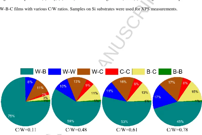
As it is shown in Fig.1, the increase of the C/W ratio caused a shift in W4f and B1s peaks toward higher binding energies, pointing towards the progressive formation of W-C bonds as well as an increase in the B-C bond content, respectively. Additionally, an increase in the intensity on the low-energy side of the C1s spectra was observed, suggesting an increase in the C-B and C-W bond content in the sample with higher C/W ratio. By considering all the spectra simultaneously, the relative contribution of different bonds in the coating was calculated using the following equations. The relative contribution of the bonds among identical elements was calculated as RX-X = CX · fX-X, where Cx is the relative content of element X in the sample and fX-X is the relative fraction of the X-X bond in the high-resolution spectrum of element X. The relative contribution of bonds between two different elements was calculated as RX-Y = CX · fX- Y + CY · fY-X, where Cx and Cy are the relative contents of element X and Y in the sample and fX-Y and fY-X are the fractions of the X-Y bond in the high-resolution spectrum of element X and of the Y-X bond in the high-resolution spectrum of element Y, respectively. This relative bond content is plotted in Fig. 2. The W-C bond content was found to increase from ~11% to ~17%
when the C/W ratio increased from 0.11 to 0.78. The fraction of the B-C bonds increased from
~3% to ~15% at the same time. The C/W ratio increase was also reflected in a decrease in the W-B bond content and increase in the content of C-C as well as W-B bonds. In particular, as the C/W ratio increased from 0.11 to 0.78, the W-B bonds content decreased from ~ 75% to ~ 45%, while the fraction of C-C bonds increased from ~2% to ~6%. Although the increase in the C/W ratio corresponds to a decrease in the total content of W in the coating, an increase in the fraction of W-W bonds from ~ 8% to ~17% was observed. Since the amount of B in the deposited coatings was almost constant, this result may indicate the preferential formation of
ACCEPTED MANUSCRIPT
10
B-C bonds instead of W-B bonds. Thus, more W was available to form W-W bonds. However, the higher fraction of bonds designated as W-W can be also explained by a higher fraction of C-W-B bonds as well.
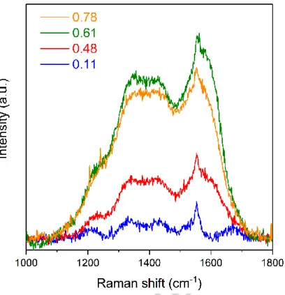
Raman spectroscopy was further used to investigate the nature of the carbon phase in the coatings. Fig. 3 depicts the Raman spectra of coatings with different C/W ratios. The spectra exhibited two broad dominant peaks characteristic for sp2 sites of disordered carbon at ~1380 cm-1 (D peak) and of ordered graphite at ~1580 cm-1 (G peak). The intensity of the Raman signal for the coating with C/W ratio of 0.11 was very low suggesting a negligible content of free carbon (C-C bonded) phase in this coating. As the C/W ratio increased to 0.48 and 0.61, the D and G bands grew in intensity indicating incorporation of more free carbon in the coatings. As the C/W ratio was increased further, the intensity of the Raman signal and thus the estimated amount of the incorporated free carbon in the coatings remained almost constant.
This confirmed the findings from XPS.
3.1.3. Microscopic evaluations
The surface morphology and the cross-section of the coatings deposited on Si substrate are shown in Fig. 4. The microstructure of the coating with the lowest C/W ratio of 0.11 was compact throughout the whole thickness and exhibited a defect free granular structure. The coating with the C/W ratio of 0.48 exhibited a fine fiber microstructure. Further increase of C/W ratio to 0.61 caused the formation of a columnar structure often connected with a decrease in the film density. The column width was estimated to be ~ 10 - 20 nm. Finally, with further increasing of the C/W ratio to 0.78, the coating exhibited a more pronounced columnar structure with still wider columns ~100 nm wide. These columns were further formed of finer
~10 - 30 nm wide columns. A good correlation between the surface morphology and the cross- section of the coatings was observed. The coating with the granular structure (C/W = 0.11) exhibited a smooth surface, while a progressive roughening of the surface was observed with
ACCEPTED MANUSCRIPT
11
the increasing of the C/W ratio due to the formation of an increasingly pronounced columnar structure.
The transition from the compact granular structure to the loose columnar structure with increasing C/W ratio can be explained in terms of energy delivered to the growing coating and the momentum transfer between the impinging particles and the growing coating [29]. The average kinetic energy of the sputtered W, B and C atoms and the backscattered Ar were calculated by SRIM [30] for the used deposition parameters. The output of SRIM simulation of the sputtered atoms was used as input for SIMTRA code [31] to simulate the particle transport from the target to the substrate at the pressure of 0.2 Pa and background gas temperature of 500°C. The relative average kinetic energy of each species arriving on the substrate was then multiplied by their relative content in the coating. This calculation provided a normalized energy delivered to the growing film by each species [32]. The Ar normalized energy was estimated by using the concentration of W in the coating, as only the W target is the source of backscattered Ar atoms. The normalized energy as the function of the C/W ratio is plotted in Fig. 5. The normalized energy for the W and B atoms and the backscattered Ar atoms decrease, while that of the C atoms slightly increases with the C/W ratio increase.
However, the total incident energy taken as a sum of normalized energy for all species clearly decreased with increasing C/W ratio.
It has been also reported that structural modification in the sputter deposited coatings is also largely momentum driven [33-35]. Since the W atom is much heavier than B and C atoms, W atoms more effectively transfer their momentum, while the momentum transfer of the lighter B and C atoms is less effective due to their reflection from the surface of the growing coating.
Consequently, momentum transfer was also reduced with increasing C/W ratio. Therefore, a decrease in the energy and momentum of the impinging species also decreased the mobility and diffusivity of the adatoms, leading to a formation of the columnar structure due to effects
ACCEPTED MANUSCRIPT
12
such as shadowing and reduced densification of the growing coating by bombarding particles [36, 37].
3.1.4. Microstructural characterization
XRD patterns of the deposited W-B-C coatings with various C/W ratios are plotted in Fig. 6.
Only a very broad diffraction peak between 30° and 50° and a second broader peak around 70°
were observed for all coatings suggesting only a short range ordering or a presence of tiny grains in the coatings [38]. As is shown in the upper part of Fig. 6, the observed features in XRD patterns can be attributed to different boride, carbide and borocarbide (WBxCy) phases, which can coexist in the deposited coatings [39]. Unambiguous identification of the present phases in the W-B-C system is not possible as several nanocrystalline phases may coexist together with a quasi-amorphous matrix providing an additional peak broadening. Fig. 7(a) shows the HRTEM image of the coating with the lowest C/W ratio of 0.11. No long-range order crystallinity was detected, however, the film also exhibits certain short range ordering that is manifested in irregular curved lattice fringes with short extension in HR images. The selected area electron diffraction (SAED) pattern shown in the inset, in agreement with XRD results, exhibits two diffused halo rings with no detectable diffraction spots, which are the characteristics of amorphous structures without long range order crystallinity.
The increase of the C/W ratio from 0.11 to 0.48 and 0.61 was followed by a growth of some crystalline clusters inside the near-amorphous matrix. These clusters of 1 – 2 nm in size with lattice fringe contrast are clearly visible in the HRTEM images shown in Fig. 7(b) and (c). In the diffraction patterns sharper, textured segments at 2.41Å are observable within the diffuse ring. The textured segments indicate lattice planes parallel with the substrate surface.
Further increase of C/W to 0.78 caused an increase of the FWHM of the XRD maxima (Fig. 6) together with an increase in the width of the halo rings in the SAED pattern (inset in Fig. 7(d)).
Amorphous structure can be detected in the corresponding HRTEM image with similar short-
ACCEPTED MANUSCRIPT
13
range ordering like in the sample with C/W ratio of 0.11 with irregular curved lattice fringes of short extension. These observations indicate an increase in the structural disordering [40]
and a transition to a near-amorphous structure.
The nanocrystalline phase was detected only for the samples with C/W ratio 0.48 and 0.61 when the chemical composition was close to the W2BC stoichiometry. Thus one can speculate on the existence of small crystallites of the W2BC phase in these two coatings, however unambiguous identification of the crystalline phase is not possible either from XRD or from
SAED patterns.
Lower magnification cross sectional TEM images can also provide some information about the film growth and larger structural defects of the deposited coatings. Fig. 7(e)-(h) depict a typical bright field cross section of deposited W-B-C films with various C/W ratios. The coating with the lowest C/W ratio exhibited a featureless, compact and defect free structure, while a progressive development of columnar structure has taken place as the C/W ratio increased. This correlates with the SEM cross-section observations and was again related to lowering of the energy delivered to the growing coating.
3.2. Mechanical properties
3.2.1. Nanoindentation measurements
Fig. 8(b) shows the variation of the hardness (H) and the effective elastic modulus (E*) as a function of the C/W ratio. The H and E* decreased with increasing C/W ratio from ~ 29 GPa to ~ 23 GPa and from ~ 500 GPa to ~ 400 GPa, respectively, which can be explained from the viewpoint of changes in the coating microstructure as well as the elemental composition and chemistry in the coating. Since the tungsten boride phases are generally harder than tungsten carbide phases [14, 41], a decrease of the hardness can be expected for higher C/W ratios as the relative amount of W-B bonds decreases in favor of mainly W-C and C-C bonds. On the
ACCEPTED MANUSCRIPT
14
other hand, the decrease of the H and E* of the deposited coating with increasing C/W ratio can also be attributed to microstructure transition from a compact and defect-free granular structure to a rough columnar structure caused by decreasing energy and momentum flux delivered to the growing coating.
The calculation of the elastic recovery (We) and elastic strain to failure (H/E*) parameters is listed in Table 2, the We and H/E* are calculated to be ~0.5 and ~0.06, respectively, for all the deposited coatings. These values are comparable to those reported for other X-B-C systems [8, 10, 14].
3.2.2. Indentation induced cracking evaluations
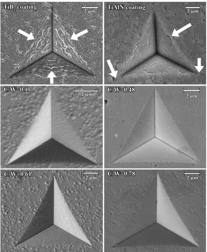
The deposited coatings together with two commercially produced state-of-the-art protective coatings were subjected to a high-load indentation tests (0.5 – 1 N) and the obtained residual impressions were studied by SEM (Fig. 9) to estimate the fracture resistance of the coatings.
The ratio of maximum indentation depth to the coating thickness was kept constant at ~ 0.9 to always have approximately the same influence of the WC-Co substrate on the crack formation and propagation. TiB2 and TiAlN reference coatings provided by a commercial manufacturer are used as a reference. Both coatings were magnetron sputtered and had the thickness of 1.2
m comparable to the presented W-B-C coatings. The TiB2 coating was composed of 38 at.%
of Ti and 62% at.% of B and exhibited a dense columnar structure. A P6/mmm crystalline unit cell with lattice parameters of 3.009 Å, 3.009 Å, 4.276 Å was detected and the crystallites were
~ 33 nm large. This structure in the hardness of 30 GPa and the effective elastic modulus of 430 GPa. The H/E* ratio of this coating was calculated as 0.070. The TiAlN coating was composed of 20 at.% of Ti, 28 at.% of Al and 52% at.% of N and also exhibited a dense columnar structure. Only a cubic Fm3m cell with lattice parameter of 4.188 Å was detected and the crystallite size was ~ 13 nm. The TiAlN coating exhibited the hardness of 28 GPa and the effective elastic modulus of 580 GPa. The H/E* ratio was 0.048. The reference coatings
ACCEPTED MANUSCRIPT
15
exhibited picture frame cracking after the high-load tests on the edges and inside of the residual indentation impressions due to lower fracture resistance of both coatings. Residual nanoindentation imprints on surface of W-B-C coatings with lower C/W ratios (0.11 and 0.48) exhibited no visible radial/edge cracks, while occasional short radial or edge cracks were visible at the indenter impressions of films with C/W ratios of 0.61 and 0.78 leading to the conclusion that the fracture resistance of W-B-C coatings slightly decreased with increase of the C/W ratio. The formation and propagation of indentation induced cracks were highly dependent on the microstructure and growth mode of thin films. Compact coatings with equiaxed grain structure generally exhibit much better fracture resistance than loose films with columnar structure [42, 43]. However, in comparison with the reference TiB2 and TiAlN coatings, all the deposited W-B-C films exhibited significantly higher fracture resistance. The results of the high-load testing were contradictory to the often-used assumption that the H/E*
ratio can be universally used as a criterion to evaluate the fracture resistance. Out of the presented coatings the TiB2 reference coating possessed the highest H/E* ratio of 0.07, the W- B-C coatings exhibited the H/E* ratio of ~ 0.06 and the TiAlN reference coating of ~ 0.05.
Therefore, the TiB2 coating should have exhibited the least cracks, the W-B-C coatings should have exhibited moderate cracking and the TiAlN should have exhibited the most cracks. Based on the presented data this was not the case. Whereas the TiB2 coating exhibited serious cracking, the W-B-C coatings exhibited little or none cracking. Thus, the H/E* ratio cannot be unreservedly used for universal prediction of the fracture resistance.
3.2.3. Micro-scratch measurements
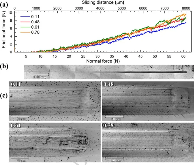
Micro-scratch measurements by a Rockwell diamond indenter were employed to assess the adhesion strength and fracture resistance of the deposited W-B-C coatings. Fig. 10(a) shows the variation of frictional force as the function of the applied normal force and the sliding
ACCEPTED MANUSCRIPT
16
distance. The frictional force curve exhibits no significant steps, indicating high scratch resistance and good adhesion of the deposited coatings. All the residual scratch tracks were nearly identical. The residual scratch track of the coating with the C/W ratio of 0.11 is presented in Fig. 10(b) as an example. It exhibits no evidence of any cohesive/adhesive failures, which is in accordance with the evolution of the frictional force curve. It indicates that the coating has undergone only elasto-plastic deformation without cracking during the scratch test [44]. An enlarged view of the highest load scratch region in Fig. 10(c) revealed that the absence of any visible significant failures such as chipping, spallation, delamination etc. in the scratch track indicated high adhesion of the coating to the substrate and confirmed also high fracture resistance [45]. In some cases, only small cracks categorized as ductile tensile cracks extended outside the scratch track. These cracks were formed due to the buckling of a film in response to a tensile stress emerging behind the moving indenter [46].
4. Conclusions
W-B-C coatings with a constant amount of boron and differing C/W ratio were deposited by co-sputtering of W, C and B4C targets at a moderate temperature. A gradual roughening of the microstructure from a dense close packed to a rough columnar structure was observed with increasing of the C/W ratio and was attributed to a decrease of the energy flux and momentum transfer to the growing coating during the deposition with the increasing C/W ratio. The level of crystallinity also changed with the C/W ratio. Whereas coatings with the C/W ratio the furthest from W2BC stoichiometric composition were near amorphous with no obvious crystallites, coatings closer to the W2BC stoichiometry were nanocomposites with small grains embedded in an amorphous matrix. All of the presented coatings classified as hard coatings with hardness > 20 GPa. The presence of nanocrystalline domains played no crucial role in determining the hardness of the coating, while the relative amount of the W-B bonds was shown to be correlated with the mechanical properties – the coating with the feature-less structure
ACCEPTED MANUSCRIPT
17
containing the highest relative amount of W-B bonds exhibited the highest hardness of ~ 29 GPa. The presented coatings furthermore exhibited high adhesion to industrially important substrates as well as scratch and fracture resistance unmatchable by current top-of-the-shelf industrial protective coatings of comparable hardness. Therefore, W-B-C coatings might pave the way for the next generation of coatings for tool protection.
Acknowledgements
This research has been supported by the project LO1411 (NPU I) funded by Ministry of Education, Youth and Sports of Czech Republic and project 15-17875S from the Grant Academy of the Czech Republic. The RBS analyses were realized at CANAM (Center of Accelerators and Nuclear Analytical Methods) under grants LM 2011019 and LM 2015056.
References
[1] R. Žemlička, P. Souček, P. Vogl, M. Jílek, V. Buršíková, P. Vašina, Y.T. Pei, On the significance of running-in of hard nc-TiC/a-C:H coating for short-term repeating machining, Surf. Coat. Technol., 315 (2017) 17-23.
[2] J.C. Sánchez-López, M.D. Abad, A. Justo, R. Gago, J.L. Endrino, A. García-Luis, M.
Brizuela, Phase composition and tribomechanical properties of Ti–B–C nanocomposite coatings prepared by magnetron sputtering, J. Phys. D: Appl. Phys., 45 (2012) 375401.
[3] N. Nedfors, O. Tengstrand, P. Eklund, L. Hultman, U. Jansson, Nb-B-C thin films for electrical contact applications deposited by magnetron sputtering, J. Vac. Sci. Technol., A, 32 (2014) 041503.
[4] P.H. Mayrhofer, C. Mitterer, High-temperature properties of nanocomposite TiBxNy and TiBxCy coatings, Surf. Coat. Technol., 133–134 (2000) 131-137.
ACCEPTED MANUSCRIPT
18
[5] L. Zábranský, V. Buršíková, P. Souček, P. Vašina, J. Dugáček, P. Sťahel, J. Buršík, M.
Svoboda, V. Peřina, Thermal stability of hard nanocomposite Mo-B-C coatings, Vacuum, 138 (2017) 199-204.
[6] H. Holleck, M. Lahres, Two-phase TiC/TiB2 hard coatings, Mater. Sci. Eng., A, 140 (1991) 609-615.
[7] C. Mitterer, P.H. Mayrhofer, M. Beschliesser, P. Losbichler, P. Warbichler, F. Hofer, P.N.
Gibson, W. Gissler, H. Hruby, J. Musil, J. Vlček, Microstructure and properties of nanocomposite Ti–B–N and Ti–B–C coatings, Surf. Coat. Technol., 120–121 (1999) 405-411.
[8] M.D. Abad, D. Cáceres, Y.S. Pogozhev, D.V. Shtansky, J.C. Sánchez-López, Bonding Structure and Mechanical Properties of Ti-B-C Coatings, Plasma Process Polym, 6 (2009) S107-S112.
[9] J.-T. Ok, I.-W. Park, J.J. Moore, M.C. Kang, K.H. Kim, Syntheses and mechanical properties of Ti–B–C coatings by a plasma-enhanced chemical vapor deposition, Surf. Coat.
Technol., 200 (2005) 1418-1423.
[10] P. Malinovskis, J. Palisaitis, P.O.Å. Persson, U. Jansson, E. Lewin, Synthesis and characterisation of Mo-B-C thin films deposited by non-reactive DC magnetron sputtering, Surf. Coat. Technol., 309 (2017) 506-515.
[11] H. Bolvardi, J. Emmerlich, S. Mráz, M. Arndt, H. Rudigier, J.M. Schneider, Low temperature synthesis of Mo2BC thin films, Thin Solid Films, 542 (2013) 5-7.
[12] J. Emmerlich, D. Music, M. Braun, P. Fayek, F. Munnik, J.M. Schneider, A proposal for an unusually stiff and moderately ductile hard coating material: Mo2BC, J. Phys. D: Appl.
Phys., 42 (2009) 185406.
[13] H. Bolvardi, J. Emmerlich, M.t. Baben, D. Music, J.v. Appen, R. Dronskowski, J.M.
Schneider, Systematic study on the electronic structure and mechanical properties of X2BC (X
= Mo, Ti, V, Zr, Nb, Hf, Ta and W), J. Phys.: Condens. Matter, 25 (2013) 045501.
ACCEPTED MANUSCRIPT
19
[14] Y.M. Liu, Z.L. Pei, J. Gong, C. Sun, Effect of carbon content on microstructures, mechanical and tribological properties and thermal stability in WBC films, Surf. Coat.
Technol., 291 (2016) 276-285.
[15] Y. Fu, B. Yan, N.L. Loh, C.Q. Sun, P. Hing, Hydrogen embrittlement of titanium during microwave plasma assisted CVD diamond deposition, Surf. Eng., 16 (2000) 355-360.
[16] Y.T. Pei, C.Q. Chen, K.P. Shaha, J.T.M. De Hosson, J.W. Bradley, S.A. Voronin, M.
Čada, Microstructural control of TiC/a-C nanocomposite coatings with pulsed magnetron sputtering, Acta Mater., 56 (2008) 696-709.
[17] N. Fairley, CasaXPS VAMAS processing software, http://www.casaxps.com/, (accessed 3 November, 2017).
[18] W.C. Oliver, G.M. Pharr, Measurement of hardness and elastic modulus by instrumented indentation: Advances in understanding and refinements to methodology, J. Mater. Res., 19 (2004) 3-20.
[19] D. Mueller, A. Shih, E. Roman, T. Madey, R. Kurtz, R. Stockbauer, A synchrotron radiation study of BaO films on W(001) and their interaction with H2O, CO2, and O2, J. Vac.
Sci. Technol., A, 6 (1988) 1067-1071.
[20] Y. Jugnet, N.S. Prakash, L. Porte, T.M. Duc, T.T.A. Nguyen, R. Cinti, H.C. Poon, G.
Grenet, Photoelectron diffraction on clean W(110) surface and bulk 4f core levels, Phys. Rev.
B: Condens. Matter, 37 (1988) 8066-8071.
[21] A. Katrib, F. Hemming, P. Wehrer, L. Hilaire, G. Maire, The multi-surface structure and catalytic properties of partially reduced WO3, WO2 and WC + O2 or W + O2 as characterized by XPS, J. Electron. Spectrosc. Relat. Phenom., 76 (1995) 195-200.
[22] D.N. Hendrickson, J.M. Hollander, W.L. Jolly, Core-electron binding energies for compounds of boron, carbon, and chromium, Inorg. Chem., 9 (1970) 612-615.
ACCEPTED MANUSCRIPT
20
[23] G. Mavel, J. Escard, P. Costa, J. Castaing, ESCA surface study of metal borides, Surf.
Sci., 35 (1973) 109-116.
[24] J. Lauridsen, N. Nedfors, U. Jansson, J. Jensen, P. Eklund, L. Hultman, Ti–B–C nanocomposite coatings deposited by magnetron sputtering, Appl. Surf. Sci., 258 (2012) 9907- 9912.
[25] W.A. Brainard, D.R. Wheeler, An XPS study of the adherence of refractory carbide silicide and boride rf‐ sputtered wear‐ resistant coatings, J. Vac. Sci. Technol., 15 (1978) 1800-1805.
[26] L.G. Jacobsohn, R.K. Schulze, M.E.H. Maia da Costa, M. Nastasi, X-ray photoelectron spectroscopy investigation of boron carbide films deposited by sputtering, Surf. Sci., 572 (2004) 418-424.
[27] P.E. Diehl, M.W. Lund, D.W. Madsen, L.C. McIntyre Jr, D.J. Smith, Characterization of WCx/B4C multilayers sputtered in reactive argon/methane atmospheres, Thin Solid Films, 239 (1994) 57-70.
[28] Y.-L. Huang, H.-W. Tien, C.-C.M. Ma, S.-Y. Yang, S.-Y. Wu, H.-Y. Liu, Y.-W. Mai, Effect of extended polymer chains on properties of transparent graphene nanosheets conductive film, J. Mater. Chem., 21 (2011) 18236-18241.
[29] H. Kersten, H. Deutsch, H. Steffen, G.M.W. Kroesen, R. Hippler, The energy balance at substrate surfaces during plasma processing, Vacuum, 63 (2001) 385-431.
[30] J.F. Ziegler, M.D. Ziegler, J.P. Biersack, SRIM – The stopping and range of ions in matter (2010), Nucl. Instrum. Methods Phys. Res., Sect. B, 268 (2010) 1818-1823.
[31] K.V. Aeken, S. Mahieu, D. Depla, The metal flux from a rotating cylindrical magnetron:
a Monte Carlo simulation, J. Phys. D: Appl. Phys., 41 (2008) 205307.
ACCEPTED MANUSCRIPT
21
[32] G. Abadias, L.E. Koutsokeras, P. Guerin, P. Patsalas, Stress evolution in magnetron sputtered Ti–Zr–N and Ti–Ta–N films studied by in situ wafer curvature: Role of energetic particles, Thin Solid Films, 518 (2009) 1532-1537.
[33] H. Windischmann, Intrinsic stress in sputter-deposited thin films, Crit. Rev. Solid State Mater. Sci., 17 (1992) 547-596.
[34] G. Greczynski, J. Lu, J. Jensen, I. Petrov, J.E. Greene, S. Bolz, W. Kölker, C. Schiffers, O. Lemmer, L. Hultman, Strain-free, single-phase metastable Ti0.38Al0.62N alloys with high hardness: metal-ion energy vs. momentum effects during film growth by hybrid high-power pulsed/dc magnetron cosputtering, Thin Solid Films, 556 (2014) 87-98.
[35] J. Houska, Molecular dynamics study of the growth of crystalline ZrO2, Surf. Coat.
Technol., 304 (2016) 23-30.
[36] M.D. Abad, M.A. Muñoz-Márquez, S. El Mrabet, A. Justo, J.C. Sánchez-López, Tailored synthesis of nanostructured WC/a-C coatings by dual magnetron sputtering, Surf. Coat.
Technol., 204 (2010) 3490-3500.
[37] J.A. Thornton, High Rate Thick Film Growth, Annu. Rev. Mater. Sci., 7 (1977) 239-260.
[38] M. Apreutesei, C. Esnouf, A. Billard, P. Steyer, Impact of local nanocrystallization on mechanical properties in the Zr-59at.% Cu metallic glass thin film, Mater. Des., 108 (2016) 8- 12.
[39] Crystallography Open Database (COD), http://www.crystallography.net, (accessed 3 November, 2017).
[40] M. Ghidelli, S. Gravier, J.-J. Blandin, T. Pardoen, J.-P. Raskin, F. Mompiou, Compositional-induced structural change in ZrxNi100−x thin film metallic glasses, J. Alloys Compd., 615 (2014) S348-S351.
[41] W. Tillmann, G. Bejarano, F. Hoffmann, Deposition of hard and adherent TiBCN films for cutting tools applications, physica status solidi (a), 209 (2012) 1520-1525.
ACCEPTED MANUSCRIPT
22
[42] L. Zhang, H. Yang, X. Pang, K. Gao, A.A. Volinsky, Microstructure, residual stress, and fracture of sputtered TiN films, Surf. Coat. Technol., 224 (2013) 120-125.
[43] O. Nakonechna, T. Cselle, M. Morstein, A. Karimi, On the behaviour of indentation fracture in TiAlSiN hard thin films, Thin Solid Films, 447–448 (2004) 406-412.
[44] A.R. Bushroa, H.H. Masjuki, M.R. Muhamad, B.D. Beake, Optimized scratch adhesion for TiSiN coatings deposited by a combination of DC and RF sputtering, Surf. Coat. Technol., 206 (2011) 1837-1844.
[45] A. Karimi, Y. Wang, T. Cselle, M. Morstein, Fracture mechanisms in nanoscale layered hard thin films, Thin Solid Films, 420 (2002) 275-280.
[46] S.J. Bull, Failure mode maps in the thin film scratch adhesion test, Tribol Int, 30 (1997) 491-498.
ACCEPTED MANUSCRIPT
23
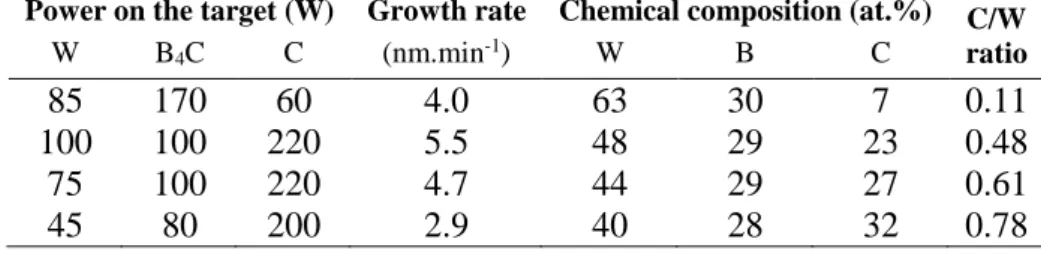
Table 1. Deposition conditions, deposition rates and compositional data of the studied W-B-C coatings
Power on the target (W) Growth rate Chemical composition (at.%) C/W ratio
W B4C C (nm.min-1) W B C
85 170 60 4.0 63 30 7 0.11
100 100 220 5.5 48 29 23 0.48
75 100 220 4.7 44 29 27 0.61
45 80 200 2.9 40 28 32 0.78
Table 2. Average values of hardness (H), effective elastic modulus (E*), H/E* ratio and elastic recovery (We) for W-B-C coatings with various C/W ratios.
C/W ratio
H E* H/E* We
(GPa) (GPa)
0.11 28.6 ± 1.5 500 ± 12 0.057 0.48 0.48 24.4 ± 1.6 410 ± 15 0.060 0.47 0.61 23.5 ± 2.1 410 ± 20 0.057 0.47 0.78 23.3 ± 1.0 400 ± 12 0.058 0.46
ACCEPTED MANUSCRIPT
24
Fig. 1. XPS spectra of (a) W4f, (b) B1s (inset shows enlarged view) and (c) C1s high resolution spectra for the W-B-C films with various C/W ratios. Samples on Si substrates were used for XPS measurements.
Fig. 2. The relative contribution of bonds in the W-B-C films with different C/W ratios obtained from XPS.
ACCEPTED MANUSCRIPT
25
Fig. 3. Raman spectra of the W-B-C films with different C/W ratios. Samples on Si substrates were used.
Fig. 4. Surface morphology (top) and cross sectional (bottom) SEM images of W-B-C coatings with various C/W ratios grown on Si substrate.
ACCEPTED MANUSCRIPT
26
0.1 0.2 0.3 0.4 0.5 0.6 0.7 0.8 0
5 10 15 20 25 30 35 40
W B Ar C total
relative average energy per atom (eV)
C/W ratio
Fig. 5. Relative average incident energy per deposited atom and back-scattered Ar atom versus the C/W ratio as determined using SRIM and SIMTRA calculations.
ACCEPTED MANUSCRIPT
27
Fig. 6. XRD patterns of W-B-C coatings with various C/W ratios. Samples on cemented carbide substrates were used for these measurements.
ACCEPTED MANUSCRIPT
28
Fig. 7. Cross sectional TEM results of W-B-C coatings. HRTEM images and SEAD patterns for W-B-C coatings with C/W ratio of (a) 0.11, (b) 0.48, (c) 0.61 and (d) 0.78. The growth direction in HR images is showing up. Cross-sectional TEM overview images for W-B-C coatings with C/W ratio of (e) 0.11, (f) 0.48, (g)
0.61 and (h) 0.78. The position of substrate-film interface is indicated in panel (h). Samples on Si substrates were used.
0.1 0.2 0.3 0.4 0.5 0.6 0.7 0.8 20
22 24 26 28
30 hardness
hardness (GPa)
C/W
400 440 480 520 560 effective elastic modulus
effecti ve el asti c modul us (GPa)
Fig. 8. Variation of hardness and effective elastic modulus for W-B-C coatings with different C/W ratios.
Samples on cemented carbide substrates were used for these measurements.
ACCEPTED MANUSCRIPT
29
Fig. 9. The high load residual indenter impressions on the surface of TiB2 and TiAlN commercial coatings and W-B-C coatings with different C/W ratios. Samples on cemented carbide substrates were used for these
measurements. The cracks in the TiB2 and TiAlN coatings are highlighted.
ACCEPTED MANUSCRIPT
30
Fig. 10. (a) Variation of frictional force as a function of applied normal force (or scratch distance); (b) scratch image of the film with C/W = 0.11, (c) high load region of the scratch track of the films with various C/W ratio.
Samples on cemented carbide substrates were used for these measurements.
ACCEPTED MANUSCRIPT
31 Highlights
- W-B-C coatings with varying C/W content ratio were prepared by magnetron sputtering
- Evolution of the coating microstructure was correlated with W atom flux
- Chemical composition was key parameter influencing precipitation of crystallites - Hardness was governed by microstructure and relative amount of W-B bonds