Budapest University of Technology and Economics Department of Polymer Engineering
D EVELOPMENT OF C YCLIC B UTYLENE T EREPHTHALATE M ATRIX
C OMPOSITES
– P H D T HESIS –
Written by: Gábor Balogh M.Sc. Mechanical Engineer
Supervisor: Dr. Tibor Czigány Professor
- 2012 -
Nyilatkozat
Alulírott Balogh Gábor kijelentem, hogy ezt a doktori értekezést magam készítettem, és abban csak a megadott forrásokat használtam fel. Minden olyan részt, melyet szó szerint vagy azonos tartalomban, de átfogalmazva más forrásból átvettem, egyértelműen a forrás megadásával jelöltem.
Budapest, 2012. április 10.
Balogh Gábor
Acknowledgements
I would like to express my thanks to my supervisor, Professor Tibor Czigány for his help and support of my work and his guidance towards a deeper scientific way of thinking. Here, I also have to say thank you to my mentor, Pál Szaplonczay, who introduced me the exciting world of the high voltage technology and to Professor József Karger-Kocsis who foreshowed me reactive polyesters. I am grateful to all my colleagues and friends at the Department of Polymer Engineering for their help and the creative atmosphere. I would also like to express my thanks to my students (Márk Móró, Sándor Hajba, István Csákvári) who helped a lot with my work.
I am grateful to Sergiy Grishchuk and Markus Steeg at Institut für Verbundwerkstoffe (Kaiserslautern, Germany) and to Tobias Abt at Centre Català del Plàstic (Terrassa, Spain) for their generous help with regard to my work. I would like to say ‘thank you’ to Thorsten Hartmann (Cyclics Europe GmbH) for the GPC analyses; to Ralf Thomann (Universität Freiburg) for the TEM pictures; to Anton Apostolov for the X-ray spectra; to Balázs Ring for the heat and thermal conductivity examinations. I would like to express my thanks to Cyclics Europe GmbH for providing the necessary CBT160 for my work; to Perstorp Holding AB for supplying the polycaprolactone and to XG Ssciences Inc. for the graphene.
Last, but not least I would like to express my thanks to my family and friends for their unbroken support of my work.
The work reported in this thesis has been developed in the framework of the project "Talent care and cultivation in the scientific workshops of BME" project. This project is supported by the grant TÁMOP - 4.2.2.B-10/1--2010-0009.
This work is connected to the scientific program of the "Development of quality-oriented and harmonized R+D+I strategy and functional model at BME" project. This project is supported by the New Széchenyi Plan (Project ID: TÁMOP-4.2.1/B-09/1/KMR-2010-0002).
Table of contents
List of abbreviations and symbols ... 2
1. Introduction ... 5
2. Literature overview... 7
2.1. High voltage overhead transmission lines (HVTL) ... 7
2.2. Solutions for HVTLs ... 8
2.3. Polymeric composites ... 10
2.4. Cyclic butylene terephthalate (CBT) ... 13
2.4.1. Properties of cyclic butylene terephthalate ... 16
2.4.2. Properties of polymerized cyclic butylene terephthalate ... 21
2.4.3. Chemical modification and other toughening methods of pCBT ... 22
2.4.4. Composites made with pCBT matrix ... 25
2.4.5. Reactive processing techniques for CBT ... 27
2.5. Pultrusion ... 29
2.5.1. Thermoplastic pultrusion of preimpregnated reinforcements ... 31
2.5.2. Injection pultrusion of thermoplastics ... 33
2.6. Critical review of literature, aims of the thesis ... 35
3. Materials and methods ... 37
3.1. Applied materials ... 37
3.2. Applied experimental methods ... 38
3.2.1. Characterization methods ... 38
3.2.2. Mechanical tests ... 41
3.3. Sample preparation ... 42
3.3.1. Samples for characterizations ... 42
3.3.2. Composite samples ... 43
3.3.3. Torque curves ... 45
4. Results and discussion ... 47
4.1. Characterizations of CBT ... 47
4.1.1. Properties of neat CBT ... 47
4.1.2. Effect of polycaprolactone ... 52
4.1.3. Effect of graphene ... 57
4.1.4. Short summary of characterizations ... 65
4.2. Pultrusion technology development ... 66
4.3. Mechanical testing ... 74
4.3.1. Samples made by the in-situ melting and polymerizing method ... 74
4.3.2. Prepreg method – effect of polycaprolactone ... 76
4.3.3. Premix method – effect of graphene ... 80
5. Summary ... 85
5.1. Utilization of results ... 87
5.2. Theses ... 89
5.3. Further work ... 91
6. Literature ... 92
7. Appendix ... 104
List of abbreviations and symbols Abbreviations
ACSR Aluminum conductor steel reinforced
AFM Atomic force microscopy
BPADGE Brominated bisphenol-A diglycidyl ether CBT Cyclic butylene terephthalate
CF Carbon fiber
CNT Carbon nanotube
CTE Coefficient of thermal expansion
DC Displacement control
DMA Dynamic mechanical analysis DSC Differential scanning calorimetry
FBG Fiber Bragg grating
FTIR Fourier transform infrared spectroscopy GE General Electrics Corporation
GPC Gel permeation chromatography
HDT Heat distortion temperature
HFIP Hexafluoro-2-propanol
HVTL High voltage transmission line
IHP Interval hot press
ILS Interlaminar shear
IM Injection molded (specimen)
ISP In-situ polymerized (specimen)
MDSC Modulated differential scanning calorimetry
MMT Montmorillonite
MN Number average of molecular weight
MP Peak value of molecular weight
MW Mean molecular weight
MWCNT Multiwalled carbon nanotube
NMR Nuclear magnetic resonance
o-DCB Ortho-dichlorobenzene
OGTR Tetrakis(2-ethylhexyl)titanate
PA Polyamide
PAN Polyacryl nitrile
PBT Polybutylene terephtalate
PC Pressure control
pCBT Polymerized cyclic butylene terephtalate
PCL Polycaprolactone
PDMS Polydimethylsiloxane
PEEK Polyether ether ketone PEKK Polyether ketone ketone
PPS Polyphenylene sulfide
RIM Reaction injection molding
ROP Ring opening polymerization
RTM Resin transfer molding
SAXS Small angle X-ray scattering SEM Scanning electron microscope
SMA Shape memory alloy
TBBPA Tetrabromobisphenol-A
TEM Transmission electron microscopy
TGA Thermogravimetry
THF Tetrahydrofuran
TiN Titanium Nitride
UD Unidirectionally aligned
UV Ultraviolet radiation
VARTM Vacuum-assisted resin transfer molding WAXS Wide-angle X-ray scattering
WGF Woven glass fabric (reinforced specimen) XB0, 1, 2 and 3 Experimental batches of CBT
α Crystalline type of pCBT
β Crystalline type of pCBT
Symbols
Acomp [mm2] Cross section area of the composite in the pultruder Acomp,m [mm2] Matrix cross section area of the composite profile Ainj [mm2] Cross section area of the injector
b [mm] Specimen thickness d [m] Lamellae distance
E [J] Energy
I [A] Electrical current
l [m] Length
Ldie [m] Pultrusion die length
Linj [m] Length of the injector system n [-] Reflexion order (Bragg eq.) Q [g/min] Mass flow
tdie [s] Time spent inside the pultruder die Tg [°C] Glass transition temperature Timp [°C] Temperature of impregnation tinj [s] Time of injection
Tinj [°C] Temperature of injection Tm [°C] Melting temperature
tn [mm] Distance between the notches Tpoly [°C] Temperature of polymerization
ttotal [s] Total time spent in molten state (pultrusion)
U [V] Voltage
V [cm3] Volume
Vf [-] Fiber volume fraction vinj [m/min] Flow speed in the injector Vm [-] Matrix volume fraction vproc [m/min] Process speed
Wi [-] Mass fraction
αheat [W/mK] Coefficient of thermal conductivity αr [-] Primary thermal relaxation
βr [-] Secondary thermal relaxation ΔHc [J] Crystallization enthalpy
ε [%] Deflection
ἐ [1/s] Deformation speed
Θ [°] Bragg angle
λ [m] Wavelength
ρf [g/cm3] Density of the fibers ρm [g/cm3] Density of the matrix ρs [Ohm/cm] Specific resistivity σc [S/m] Conductivity
τdin [kJ/m2] Dynamic interlaminar strength χc [%] Crystalline fraction
ω [rad/s] Angular velocity
1. Introduction
Nowadays electricity-usage is increasing extremely fast due to globalization, and widespreading of household utilities such as air conditioning devices (Table 1). Production possibilities of this energy is given (by water, gas or nuclear power plants) but transmitting this faces problems – remember the northeastern US blackout in August 2003 which was caused by the obsoleting high voltage transmission lines (HVTL) and their sagging [1].
Electrical energy consumption [TWh]
Year 1990 2000 2005 2009 2010 2011
Hungary 35 33 35 37 38 42
European Union 1803 2528 2661 2926 2906 3037
USA 2923 3356 3660 3829 3873 3873
China 580 1014 1630 3428 3438 3503
Table 1. World electrical energy consumption between 1990 and 2011 [2]
The transmission technology utilized nowadays that applies only metallic parts has faced its frontiers because only a given amount of electrical energy can be transferred through a cross section unit due to the temperature rise in the wires (the limit is 80°C) [3]. Another problem is wire sagging between the poles. This phenomenon is caused by thermal expansion and material structure: the wire gets warm and elongate and is capable to deform elastically and as a consequence of this its own weight bends the wire, so it gets closer to the ground. To minimize sag, low pole distances and high poles are utilized. Sagging is to be avoided because a strong electromagnetic field is generated around the wire and if it gets too close to the ground it may cause health problems. According to earlier studies inhabitants living close to HVTLs have problems like leucosis and sleep disorders more likely [4]. A further problem with metallic parts is corrosion due to the presence of water mainly in the inner steel core.
A possible solution for the problems described above is replacing some metal parts with polymeric composite materials. Their main application in HVTLs may be the load-carrying inner core. Suitable composite materials have much higher stiffness-to-weight ratio than steel [5, 6] so sagging would be reduced which results in a reduction in the above mentioned problems.
For high-tech composites nowadays mostly thermosetting materials (generally epoxy resins) are used. Epoxy resins have excellent mechanical properties that make them
suitable for being used as the inner core of a HVTL cable but they are problematic to recycle and tend to micro-crack. Moreover, these resins have to be cured which makes production times longer. To solve these problems a new generation of thermoplastic matrices can be utilized, like the in-situ polymerizable cyclic butylene terephtalate (CBT) oligomer system. It is in solid state at room temperature and has water-like melt viscosity (below 0.1 Pas) above its melting point which makes fiber wet-out easy and polymerizes fast among the reinforcing fibers. Since this is a brand new matrix material no industrially applicable processing technology is developed yet. To process CBT new low pressure technologies may be utilized, which consume much less energy than the currently applied thermoplastic processing technologies. Composite materials with this new CBT matrix are capable to replace the conventional steel cores of HVTLs.
Since CBT is a low viscosity thermoplastic semi-finished composite parts, such as sheets or preforms and tapes may easily be processed with this matrix system. Such materials are highly desired by the composite industry, especially for automotive applications.
The aim of this PhD thesis is to develop composites with CBT matrix which possesses appropriate properties to serve as an inner core of a HVTL. It is also desired to develop technologies for processing CBT into a proper composite matrix material.
2. Literature overview
In this chapter the main elements of high voltage transmission lines are introduced as well as polymeric composites are also discussed extensively. Polymeric matrices, especially thermoplastic ones, their modifiers, fillers and reinforcing fibers are described here.
2.1. High voltage overhead transmission lines (HVTL)
Electrical energy transmission systems consist of three main parts: the wires themselves, poles and insulators. Utility poles are the base holder elements of the HVTL system and from the technical point of view they are truss grudgers. Their main task is to ensure the appropriate distance between the ground and the wire. Their sizes are mainly defined by the wire voltage and ground characters [7]. Wires are held on the poles by insulators. Their main task is to ensure insulation and to avoid short-circuit between poles and wires.
Nowadays most of the insulators are made of glass-fiber reinforced composite and silicone, but some ceramic and glass ones are also in use [7]. Main task of wires is to transfer electricity. Normally wires are made of metallic materials as they have the best electrical conductivity properties among the suitable materials. These wires consist of an inner and an outer layer. The inner core carries most of the mechanical load and is made of steel, while the outer layer transmits most of the electricity due to skin effect. However, the inner core still has to be conductive [7]. This steel-aluminum system is called ACSR (Aluminum Conductor Steel Reinforced).
Due to high electrical load these wires get warm, and which causes elongation due to thermal expansion, so they get closer to the ground. This phenomenon is called sagging and should be avoided. This sagging is a mechanically problematic effect and causes other problems: The so called electrosmog, an electromagnetic field surrounding the wire [8] can cause health problems like leucosis and sleep disorders reported by Varga [4], other psychological effects are reported by Beale et al. [9]. Sagging is a function of coefficient of thermal expansion (CTE), the distance between the poles and the sag itself (the equation for describing sag is not discussed here as it does not belong to this work) and the higher these values are, especially CTE, the higher the sag is. To avoid sag, utilization of low CTE materials or reduction of transferred electricity is necessary. As the latter is not a viable route low-CTE solutions will be discussed hereinafter.
2.2. Solutions for HVTLs
As mentioned already, low CTE materials should be applied in the high voltage field. Such materials may be special metals, or composites.
In HVTLs some composite parts are already applied, such as glass fiber reinforced composite based insulators. This insulating technology was developed in the 1960s [10], became widespread in the 1970s and 80s and by nowadays it is used all around the world even above 700 kV [11]. The advantage of using glass fiber reinforced composite materials in insulation technology is their light weight compared to ceramic ones, non-conductivity, high strength and outdoor-resistivity.
Utility poles may also be made of composites. These poles were first used in Hawaii to replace wooden poles because composites have much better corrosion resistance [12].
These poles have an extreme long service life of up to 80 years if appropriate UV protection is applied [13].
Apart from poles, composites are also necessary in wires. As it was mentioned above, HVTLs are composed of an inner core and an outer coating, and composites are suitable replacement for steel inner cores as it was reported by Alawar et al. [14, 15]. However, only carbon fibers are appropriate reinforcements because other fibers do not transmit electricity [16]. Another problem arises if carbon fibers are utilized, namely galvanic corrosion between the carbon and the aluminum interface so these two materials have to be galvanically separated. This problem is described in the literature much more detailed, for example in [17]. This issue will not be discussed since the solution is simple; an insulating layer has to be applied.
Special low CTE wires were developed by several companies and research groups:
A nickel-containing wire system was developed by VISCAS Corp. (Japan) under the trade name of INVAR®. In this wire the inner core is made of nickel-steel alloy wires and the outer layer is made of aluminum-zirconium alloy. Due to similar strength properties and
~60% less thermal expansion these wires can operate at up to 230°C. Their only drawback is the price, which is approximately ten times more than conventional wires (Figure 1/a) [18].
3M Corp. (USA) has developed a metal matrix composite inner core with alumina fibers in alumina matrix. The outer layer is an Al-Zr alloy. This system also ensures low sag at high temperatures and higher tensile strength than conventional ACSR systems (Figure 1/b).
Widespreading of this system is hindered by its price, which is approximately ten times higher also than that of ACSR [19].
Carbon fibers are already utilized in HVTLs. In this case the inner core is made of a pultruded carbon and glass fiber reinforced rod with a special heat resistant epoxy matrix [20]. Electricity-transmitting aluminum wires are twisted around this rod (Figure 1/c).
Glass fibers are necessary to avoid galvanic corrosion [17] which comprises the functionality of the wire. This system was developed by Composite Technology Corporation (CA, USA) in the early 2000s and has been used in several countries in the world [21]. This technology is protected by patents [22, 23]. However, these composites may have critical bending loads leading to cable failure according to Burks et al. [24, 25].
Such bending loads occur if the cable is bent for example over mandrels and showing that apart from epoxy resins other matrix materials should be investigated. Note, that due to thermal expansion the aluminum outer core loosens around the inner composite core during peak loads. If the cable cools down, the outer core re-fastens. This is a complicated issue from the point of the transmission lines, but out of scope of his thesis.
a) b) c)
Figure 1. Wire systems with low CTE: special steel wire (a), metal matrix composite system (b), polymer composite system (c). Core diameters are 9.53 mm – these samples are Drake cables [18, 19, 26]
High voltage insulators and conductors are fixed with fittings which are crimped onto them. An example of this is shown in Figure 2/a. This so-called crimping technology is critical and has to be carried out with care. A strong contact has to be present between the rod and the fitting during the whole service lifetime of the insulator or conductor which is at least 30 years. The crimping should not affect tensile properties during this timeframe.
Crimping is carried out with special presses with usually 8 or 8+8 dies (Figure 2/b) with a pressure that does not break the composite part inside. Once a conductor is developed based on polymeric materials this problem has to be dealt with [27].
1 cm 1 cm 1 cm
a) b)
Figure 2. a) End fitting of a high voltage composite insulator: 1 – glass fiber/epoxy composite rod;
2 – metal end fitting; 3 – silicone weather sheds; b) Crimped end-fitting with 2x8 + 2x8 pressing dies [27]
2.3. Polymeric composites
Polymer composites are multi-phase materials where strong adhesion bonds the tough matrix to the high strength reinforcement. This adhesive contact remains stable in high stress conditions [6]. In this chapter general properties and base element of composites will be introduced.
The advantage of applying composites is utilizing the synergy of matrix toughness and fiber strength. If adhesive connection is achieved between them the positive properties of both materials can be used.
As reinforcements usually fibrous structures are applied due to their high surface-to- volume ratio. This is important because in composites the higher the surface the higher the area for adhesion [28, 29]. In this work only carbon fibers are studied as this type of fibers have the highest electrical and heat conductivity among reinforcing fibers. This conductivity is so high that carbon fibers are applied even in sensor technology [30]. Do not forget, that these fibers possess also low, even almost zero thermal expansion, which helps to avoid sagging [31].
Carbon fiber production starts with a precursor fiber which is carbonized and then graphitized throughout the manufacturing process. Different surface treatments are applied after graphitization. Finally the fiber is wound up [26]. Fiber precursors may be made of poly acryl-nitrile (PAN), viscose, pitch, rayon or even Kevlar®. Properties of different precursor-based fibers are listed in Table 2. In this study only PAN-based carbon fibers are used as these fibers are available in Hungary (Zoltek has a plant in Nyergesújfalu) and they are the the most widespread in the industry. These PAN fibers are produced via wet spinning (Figure 3) and then stabilized in oxygen atmosphere at 200-300°C under tension.
The next step is carbonization where the heated fiber is also under tension but an inert atmosphere is applied. The whole process is presented in Figure 4. Properties of the fibers are set by the temperature of this phase: above 2000°C a high modulus fiber with lower
strength is produced, below 2000°C the situation is vice-versa. A commonly used PAN based carbon fiber, Panex 35 by Zoltek has a Young’s modulus of 242 GPa with a tensile strength of 3800 MPa, for properties of some high-performance polymer based ones see Table 2 [26, 31-33].
Figure 3. Wet spinning of PAN precursor fibers [34]
Figure 4. Schematics of carbon fiber production [35]
Precursor Product designation Tensile strength [GPa]
Young's modulus [GPa]
Electrical resistivity [μΩm]
Kevlar-29 1600°C 0.94 143 23
PAN T-300 3.66 231 18
Pitch P-55 1.90 415 9
Table 2. Properties of high performance polymer based carbon fibers [26, 36]
Beside fibrous reinforcements, nano-scaled reinforcements or modifiers are also used in polymer composites. These materials mainly change the matrix-dominated properties like compressive strength and flexural strength, energy absorbing properties, heat and electrical conductivity and creeping properties [37, 38]. Among HVTLs most of these properties are critical: bending – because the conductor is between two poles and is bent by its weight;
conductivity – this material has to transmit electricity; creeping and compressive strength – fittings have to be crimped onto the conductor.
According to the above written, nano modifiers are also investigated in this work to improve mechanical and conductivity properties which may be increased by carbon
nanotubes [39, 40] or graphene [41]. Other properties may also be changed by other materials like toughening agents or chemical modifiers – these will be discussed later in Chapter 2.4.3.
In this thesis only graphene will be discussed owing to its low price compared to carbon nanotubes and in production of a conductor core low price materials should be applied.
Graphene can be simply described as a carbon monolayer (Figure 5/d) with outstanding mechanical and electrical properties. Graphene, according to Geim and Novoselov, may also be considered as a building material of all other carbon structures – see Figure 5/a, b, c [42].
a) b) c) d)
Figure 5. Graphene as a building material of all other dimensionalities: a – fullerenes; b – carbon nanotube; c – graphite; d – graphene nanoplatelets, SEM image [42]
Graphene was discovered in 2004 [43] and before that time it was believed that such a structure cannot thermodynamically exist. Graphene was reported to show reinforcing effect in nanocomposites with both thermosetting and thermoplastic matrices. According to these results graphene causes a Young’s modulus increase with some decrease in strain at break [44]. These nanocomposites can get additional carbon fiber reinforcement. Hybrid systems are producible for example by in-situ polymerization (this method is discussed later) in one step. The problem is graphene dispersion in the matrix which is similar to carbon nanotube or any other nanoparticle dispersion. Possible dispersion solutions were widely examined and three routes were described: in-situ polymerization, melt intercalation and exfoliation in solvents [38]. According to these results graphene can be dispersed in any kind of polymeric matrix.
Nowadays mainly thermosetting resins are used as matrices in high-tech composites.
However in this work these resins will not be discussed because thermoplastics are
believed to be the next generation of high tech matrices. Thermoplastics are also more environmentally friendly as they are much easy to recycle because they can be reprocessed [45].
2.4. Cyclic butylene terephthalate (CBT)
Cyclic butylene terephthalate is a cyclic oligomer system in powder or pellet form designed to be a thermoplastic matrix material for composites. This CBT is capable to polymerize into pCBT in-situ via ring-opening polymerization (ROP). The resulting polymer is chemically identical to PBT with different molecular weight and crystalline fraction, so it is designated as pCBT for clarity.
For impregnating long-fiber reinforced composites a resin of dynamic viscosity below 1 Pas is necessary. Conventional thermoplastics have much higher viscosity value (~102-104 Pas) and are mainly used with short fibers in injection molded products. So in this thesis only low-viscosity materials will be discussed. According to Steeg’s work [46], who examined thermoplastic materials, CBT has the lowest melt viscosity among the available thermoplastic raw materials on the market (Figure 6, ‘classic’ thermoplastics mean materials polymerized before usage, while ‘reactive’ thermoplastics are polymerized in- situ). This CBT polymerizes through ROP and prior to ROP the low molecular weight results in the water-like (~10-2 Pas) viscosity. For further work CBT was chosen due to this low viscosity value and only this material will be discussed in the followings.
Figure 6. Dynamic viscosity of classic and reactive thermoplastic polymers [46]
Generally, ROP means that monomers or oligomers have a ring form prior to polymerization. During the polymerization process these rings open and in the presence of a suitable catalyst form a linear polymer. If this process happens in the timeframe of manufacturing, than it means in-situ polymerization. An advantage of this is the low melt viscosity prior to polymerization because the melt consists of only small monomers or
oligomers. So impregnation should be completed before polymerization starts, and in this case no high pressures are needed. From a chemical point of view it is much easier to
‘assemble’ the molecules in-situ, than produce them, then ‘degrade’ them with high pressure as they are pressed though a reinforcing system [47, 48].
In case of CBT all of this means that this material is built up by cyclic oligomers, which are capable to polymerize into a linear polymer (for the whole process see Figure 7 and Figure 9) [47, 49].
CBT belongs to the family of polyesters and this group is proven to be excellent matrix materials for composites as described by Czigány and Karger [50].
Cyclic oligomers of polyesters were first reported by Ross et al. [51]. Starting from that time until the 1990s there was only academic interest in these cyclic structures as they were produced during conventional polyester processing in a concentration of ~1-3% and there was no use of them [52]. Later, it became clear that these molecules polymerize through ROP, form no by-product and have low melt viscosities which makes reinforcement impregnation easy. This makes it possible to use these cyclic oligomers for thermoplastic resin transfer molding (RTM), pultrusion or other hot melt impregnation processes.
Figure 7. Conversion of monomers to low viscosity macrocyclics (bottom side) allows in-situ polymerization during processing and produce more structured parts [49]
In the 1990s efforts were made at General Electric Corp. to develop a preparation method for cyclic oligomers of polyesters based on the above described processing methods. Most of this work was done by Brunelle [48] with the result of dissolving commercial PBT in dry ortho-dichlorobenzene (o-DCB) at reflux, then adding the equilibration catalyst [53]
(see Figure 8). These cyclic oligomers were then polymerized via ring-opening
Note: Ar = aromatic ring
polymerization into conventional polyesters with unusually long chains, also by Brunelle et al. [52].
Parallel to Brunelle, another research group led by Semlyen also developed a method for synthesizing and polymerizing cyclic ester oligomers and published a series of articles about their work [54-62] including a patent [63]. He also applied high dilution condensations and ring-chain equilibrium methods and the latter seemed to be more productive.
As the proper technology was developed, production of cyclic PBT oligomers started at General Electric Corp., and then the technology was acquisited by Cyclics Corporation.
From this time on cyclic butylene terephthalate oligomers are available on the global market under the trade name of CBT - as an abbreviation of Cyclic Butylene Terephthalate. Cyclics Corporation has two manufacturing plants, one in the USA (Schenectady, NY) and one in Europe (Schwarzheide, Germany).
Figure 8. Processing of cyclic ester oligomers [49, 53]
In Schwarzheide the base material for CBT production is ULTRADUR 6505 by BASF.
This PBT is cyclo-depolymerized, catalyst is added then it is ready for further processing.
Polymerization of CBT is the already mentioned ROP where the rings are opened by heat in the presence of a suitable catalyst. For commercial use, a TiN based catalyst (butyl chlorotin dihydroxide), Fascat 4101, is used which is manufactured by Arkema.
Polymerization method is as follows (Figure 9): in the initiation phase cyclic oligomers are opened by heat and initiator and start to polymerize (in this case the initiator is butyl chlorotin dihydroxide) into linear pCBT. pCBT refers to polymerized CBT and considered
to be chemically identical to conventional PBT [64, 65] with higher molecular weight [66].
The propagation phase is similar to chain-growth polymerization processes. Initiators are believed to operate by Lewis acid activation of the ester group and then transferring a ligand and forming a new ester bond and an active chain end (Figure 9). Propagation continues until most cyclic oligomers are depleted and the ring-chain equilibration deteriorates [48, 52, 66].
Figure 9. Polymerization and propagation of cyclic butylene terephthalate oligomers [49, 52]
2.4.1. Properties of cyclic butylene terephthalate
Cyclic butylene terephthalate is available in powder and pellet forms with (CBT160) and without (CBT100) catalyst [67]. CBT without catalyst is mainly used as viscosity reducing agent for other polymers or as an additive for rubbers and epoxies [68, 69]. This CBT without catalyst is out of scope of this thesis so will not be discussed further here. In this thesis CBT refers to CBT160, the catalyzed version of this matrix material in the followings.
CBT oligomers contain 2-7 monomers (for atomic structures of a tetramer see Figure 10) and polymerizes via a ring-opening way which is entropically driven, athermic and no by- product is formed. This latter property is important in industrial applications because no or much less ventilation is necessary contrary to crosslinking resins.
This ROP reaction can be frozen by decreasing the temperature and the oligomer conversion-time-temperature function can be examined for example by gel permeation chromatography (GPC). This work was done by Steeg in his PhD thesis (Figure 11) [46].
a) b)
Figure 10. CBT tetramer in two different conformations at different energy levels: 998 kJ/mol (a), 950 kJ/mol (b) [46, 70]
To achieve a conversion of 95% at least 15 minutes are required at 190°C (see Figure 11/a). For continuous processing methods this is intolerable, for cyclic processes like thermoplastic RTM it is also long. So the above 200°C temperature range should be chosen where at 250°C a conversion of at least 98% is reached in 2 minutes (Figure 11/b). These results are reported by Steeg and based on kinetic studies and modeling [46].
a) b)
Figure 11. Polymerization of CBT160 in function of time and temperature (a); Time-Temperature- Conversion diagram for isothermal conditions (b, modeled values) [46]
Polymerization and crystallization of CBT
Polymerization of CBT was investigated by some researchers. Hakmé and coworkers [71]
followed polymerization by dielectric sensing and found that below 200°C polymerization and crystallization of CBT occurs parallel. Between 200 and 220°C the material first polymerizes and then crystallizes and above the melting point (220°C according to the article) no crystallization occurs.
Tripathy et al. [72] investigated the effects of different catalysts and polymerization temperatures on CBT. This research team worked together with Cyclics Corp. and used experimental batches of CBT designated as XB2 (catalyzed with stannoxane) and XB3 (catalyzed with butyltin chloride dihidroxide) and OGTR (catalyzed with tetrakis-(2-
ethylhexyl)titanate. According to their results XB2 completes the in-situ polymerization within 2-3 min, necessary for reaction injection molding (RIM), at polymerization temperatures of 165°C and higher. If XB3 or OGTR are used 15 minutes of induction time was obtained which is ideal for the resin transfer molding (RTM) technique. Their further results showed that OGTR initiator results in the highest-molecular-weight polymers (5.47x10⁴ g/mol at 200°C) among all initiators used, and the molecular weight remains the same irrespective of polymerization temperature. However, the molecular weight using XB3 initiators is about 90% (4.62x10⁴ g/mol at 200°C) of that of the OGTR system when the polymerization temperature is higher than 200°C. Stannoxane catalyzed systems give the same molecular weight at all polymerization temperatures (eg. 4.1x10⁴ g/mol at 185°C) and are around 75% of that of the OGTR-catalyzed polymer. According to WAXS results, crystallinity increases with increasing polymerization temperature in the XB3 system (64%
at 185°C, while 68% at 205°C) due to kinetic control in the examined temperature range, but a reverse trend was noticed both in XB2- and OGTR-catalyzed systems (66 and 60%
was found, respectively). The XB3-catalyzed pCBT crystallizes faster than the OGTR.
Tripathy et al. besides his above mentioned work carried out fire-resistance tests [73] with several additives for CBT like BPADGE; TBBPA and Carbinol PDMS. They utilized in- situ polymerization and stated that pCBT with these additives are applicable as high performance thermoplastic matrix materials for composites. These materials may even be used by the army and the navy. Some copolymers (eg. (50/50, w/w) pCBT/BPADGE) produced by this research group showed not only better flame retardancy properties than that of Kevlar, PEEK (commercial products from DuPont) and Ultem (product of GE) but also showed enhanced processing properties.
Harsch and his colleagues [74] followed the polymerization and crystallization of CBT by Fiber Bragg Grading (FBG) and normal force measurements at isothermal conditions. Two temperatures were chosen: 170 and 190°C. According to their results crystallization of CBT occurs in two steps: In the first stage shrinkage of several hundred ppm/min was observed while in the second stage this value was several tens according to FBG results. A difference in crystallinity and crystallization parameters was also found: at 190°C slightly more perfect crystals grew and crystallinity was also slightly higher than at 170°C.
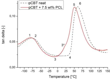
Mohd Ishak, Karger-Kocsis and their research team published a series of articles regarding polymerization and composites of CBT [75-78]. In one of these articles [78], related to a modulated differential scanning calorimetry (MDSC) study on CBT polymerization, it was
found that polymerization of CBT may not be athermic, if the exothermic peak found on the non-reversing belongs to the polymerization. This shows a heat release of 22 J/g. The authors draw a consequence on the basis of additional rheological measurements that this peak belongs to the initiation of the reaction. So the athermic reaction is a sum of an exothermic initiation/polymerization and a subsequent melting of the resulting pCBT, which is endothermic. An also interesting result is the ‘double melting characteristics’
which appears during the polymerization above the melting point (Tm) of (the resulting) PBT. This phenomenon is assigned to the remelting/recrystallization process, which is already known among PBTs.
Another article by Karger-Kocsis et al. [77] is also based on modulated DSC, and was published about organoclay-modified pCBT. Samples were produced in two ways, dry and melt blending, and then polymerization was studied. Results showed that sample preparation affects crystallization and melting behavior, and the presence of organoclay induces more perfect crystals to grow.
Lehmann and Karger-Kocsis [79] studied the isothermal and nonisothermal crystallization kinetics of CBT and compared it to classic PBT. For this study CBT XB3, CBT160, PBT B4520 and B6550 (the latter is the raw material of CBT) was used. In case of isothermal experiments at 250°C morphology of the growing crystals do not change with crystallization temperature except for PBT B6550 where geometry of growing crystal phase depends on the crystallization temperature. For the different kinds of CBT athermal nucleation was assumed due to the presence of the catalyst. In case of CBT160, the Avrami exponent is n~3, showing a spherical crystal growth, while n~2 for CBT XB3 indicating a plate-like two dimensional crystal growth. These results were compared to commercial PBTs: in case of B4520, the Avrami exponent was found to be n~4 showing thermal nucleation with spherical crystal growth and for PBT B6550 n~3 was found and in this case n~3 means athermal nucleation with three-dimensional crystal growth or thermal nucleation plate-like crystal growth. Additionally their results showed that crystallization of pCBTs occurs in a temperature range where a change in activation energy takes place.
Drying of CBT
CBT as a polyester is very sensitive to air humidity before processing. It takes the humidity up from the air which hinders polymerization through deactivating the catalyst so conversion will not be completed. According to [46] the aim is to reach a moisture content below 200 ppm. The necessary times for drying regarding the forms (eg. pellet or powder)
of CBT and the drying methods are depicted in Figure 12. After drying CBT should be kept in a desiccator or stored under nitrogen atmosphere [46]. For industrial use an on-line drying system may be useful. After polymerization pCBT has the same moisture uptake and excellent outdoor resistivity properties as conventional PBT.
Figure 12. Necessary drying times for different forms of CBT with different methods [46]
Rheological properties
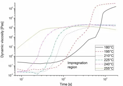
Dynamic viscosity of CBT changes in time and temperature during its processing (see Figure 13) [76]. This property is very important in case of processing CBT, so researchers have studied it in detail, as presented in the followings. Rheological properties were examined by Mohd Ishak et al. [76]. They stated that viscosity curves below 210°C have a constant initial stage where viscosity is below 1 Pas which is ideal for impregnation [80, 81]. After this constant stage viscosity starts to increase. The speed of this increase and the slope of the curve is related to polymerization speed [76].
Figure 13. Dynamical viscosity of CBT in function of time and temperature [76]
2.4.2. Properties of polymerized cyclic butylene terephthalate
CBT can be polymerized into pCBT by different methods, as it is presented here by summing up the results of some research teams. For the detailed values see Table 3. Parton et al. [64] used resin transfer molding (RTM) with a subsequent in-situ polymerization step at different temperatures, 190 and 230°C respectively. According to their results, higher polymerization temperature resulted led to higher tensile strength, elongation at break and molecular weight (MW). Crystallinity of this higher temperature sample was lower, which explains the better mechanical performance.
Abt et al. [82] used in-situ polymerization method in a hot press at 250°C. This resulted in high elongation at break and low crystallinity, but low MW and moderate tensile strength and Young’s modulus.
Baets et. al. [83-85] used similar RTM method like Parton at 190°C and achieved good results: a Young’s modulus above 3 GPa, and tensile strength above 60 MPa. Crystallinity of the samples were different, and the highest value resulted in rigid material with only 1.9% elongation at break.
Mohd Ishak et al. [75] used in-situ polymerization method in a hot press, like Abt, but at 190°C. Their results show high crystallinity, and as a consequence, low elongation at break and moderate Young’s modulus and tensile strength.
From the above one can conclude that some kind of toughening is necessary for CBT to reduce its brittle nature. The known solutions for this problem are discussed in the next chapter.
Processing
temperature [°C] E [MPa] σbreak
[MPa] εbreak [%] χc [%]
(DSC)
MW
[kg/mol] Reference 190 3.2±0.1 54±5 1.6±0.2 47±2 61.4±0.5 Paron et al.
[64]
230 3.1±0.2 73±14 2.3±0.7 42±2 73.3±0.6
250 2.7±0.3 56±8 6.7±2.9 29.6 22.6
Abt et al.
[82]
190 3.2±0.1 74±4 3.8±0.7 43 104
Baets et al.
[83]
190 3.1±0.1 74±4 3.9±0.7 42.5 -
Baets et al.
[84]
190 3.5±0.1 61±3 1.9±0.1 44±1 78
Baets et al.
[85]
190 2.3±0.1 58±2 2.3±1.6 48.6 - Mohd Ishak
et al. [75]
Table 3. Properties of in-situ polymerized cyclic butylene terephthalate samples
2.4.3. Chemical modification and other toughening methods of pCBT
Chemical modification or other kind of toughening of pCBT may be necessary due to its rigid nature caused by the crystalline structure, and the high crystalline fraction (Table 3).
Increasing toughness is possible through making crystals less perfect or using chain extenders and nonisothermal processing methods [53, 86]. Most of these methods are patented without industrial realization only studied by researchers [87-89].
Polycaprolactone (PCL) is a polyester, that polymerizes via ring-opening polymerization from ε-caprolactone monomers and is used as an additive to modify the end use properties of polymer products. As a catalyst for ROP TiN-based materials are used like in the case of CBT. So either the monomer or the polymer may be used as a toughening agent for pCBT because during the ROP, CBT can either copolymerize with ε-caprolactone monomer or PCL [90]. Based on the above these materials were examined by several research groups [85, 91, 92]. These works are reviewed in the followings.
Tripathy et al. [91] used CBT and ε-caprolactone to produce copolymers. A CBT without catalyst was used. First, liquid CBT was mixed with ε-caprolactone then stannoxane catalyst was added. Polymerization temperature was 180-185°C. The obtained material was investigated by the following methods: GPC, NMR Spectra, FTIR, DSC, DMA, WAXS. Dielectric and mechanical properties were also determined. Results showed that conversion was around 95% with a number-average molecular weight varying between 30- 40.000 g/mol and a polydispersity index of 2. The reaction between CBT and ε- caprolactone with stannoxane catalyst is a transesterification reaction. According to their DSC results the onset of PBT melting point decreases with the increasing caprolactone content – this is common for such random copolymers where only one component has segments long enough to allow crystallization to take place. DSC and WAXS results showed a decreasing crystallinity with increasing caprolactone content. X-ray scattering showed also that PCL sequences were not long enough to form crystalline domains if the polymer contains more than 50% pCBT. Concerning mechanical properties, increasing caprolactone content decreased tensile strength but increased the strain at break.
Baets and his coworkers [85] used polycaprolactone to form a copolymer and through this they reduced crystallinity and made pCBT tougher in this way. The structure of the formed copolymer is depicted in Figure 14.
Figure 14. Structure of the pCBT-PCL copolymer [93]
CBT-XB0-C (an unanalyzed experimental batch), as catalyst Fascat 4101 and polycaprolactone from Sigma Aldrich with an average molecular weight of 10.000 g/mol was used. Composites were also produced with an uniaxial and a biaxial E-glass fabric from Ahlstrom and Saertex Wagener, respectively. Processing method was an RTM-like vacuum-assisted process at 190°C. These composites were compared to unreinforced ones and to injection molded PBT samples. All of these samples were subjected to mechanical, viscosity, DSC and GPC tests. According to the results, initial viscosities (Figure 15/a) do not change significantly with the addition of polycaprolactone. A shifting of the melting point indicated that a copolymer was formed (Figure 15/b). GPC measurements showed that the presence of polycaprolactone hinders polymerization (Figure 15/c) but a final conversion of 99% was reached. Tensile testing of the matrix showed an increase in failure strain from ~2% to 4% with a decrease in Young’s modulus and tensile strength. In case of composites, PCL causes an increase in strain-at-break and impact resistance is more than doubled.
a)
b) c)
Figure 15. Initial viscosity at 190°C (a), differential scanning calorimetry traces (b) and conversion curves (c) of neat and 7 wt% PCL containing pCBT samples [85]
Effect of polycaprolactone on the crystallization and melting behavior of CBT was also studied by Wu and Huang [92]. Applied materials were CBT160 and Capa 6500 from Solvay Chemicals with an average molecular weight of 50.000 g/mol, and 7 wt% of PCL was added to CBT. Crystallization kinetics were studied by DSC in the following method:
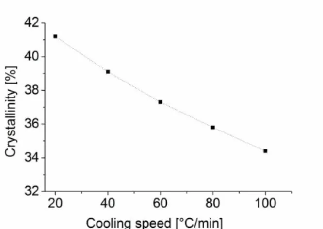
samples were heated up to 230°C, held there for 30 minutes to ensure polymerization then cooled down with different cooling speeds. Finally specimens were heated up to 265°C at a heating speed of 20°C/min to study melting properties. According to FTIR results copolymerization between CBT and PCL was a transesterification reaction. DSC results also prove copolymerization with no clear glass transition and a shifted melting point of the copolyester. An interesting phenomenon is the change of melting peaks and enthalpies caused by different heating rates. If cooling speed is below 5°C/min, only one melting peak is seen, but if cooling speed exceeds 5°C/min, two peaks can be observed due to the instable crystalline structure (two peaks: recrystallization and a subsequent melting). The slower the cooling, the higher is the melting enthalpy due to the higher crystallinity.
According to DSC results, authors stated that crystallization occurs in the cooling phase, not simultaneously with polymerization as it was reported by Baets [85]. There is a possibility for this at a temperature range between 190-202°C but supercooling is very limited so the latter process is not favorable for processing. So according to Wu’s results faster cooling results in lower crystallinity which means from a producer’s point of view that a faster cooling is necessary. This also corresponds with Steeg’s results regarding the cooling speed [46]. Note, that from one side fast cooling reduces crystallinity and results in a tougher material, from the other side this instable crystalline structure may lead to changes in the mechanical properties in longer periods of time.
Baets et al. [94] used quenching which was designated as a ‘nonisothermal method’ to toughen pCBT. The aim of this was to reduce crystallinity by fast cooling. For this work CBT100 and CBT160 and basalt fibers (ROV 1600 roving and BSL 200 weave) from Basaltex were used. Specimens were produced in a special prepreg method with a drumwinder followed by compression molding. Film-stacking was also utilized (these methods are discussed later in Chapter 2.4.5.). Two cooling speeds were applied, 8 and 100°C/min, respectively. The effect of cooling speed is clearly seen in the results of three point bending: quenched samples showed much higher flexural strength and failure strain than the slow-cooled ones. Quenching seemed to be better also in case of mode II interlaminar fracture toughness tests. Crack propagation fracture toughness was doubled by
fast cooling. This phenomenon was explained by reduced crystal perfection caused by quenching. Degree of crystallinity was the same but quenching caused defects in the crystalline structure. Changes in the crystalline structure was not studied above the glass transition range, however, it could show some recrystallization phenomenon and changes in mechanical properties.
Abt and coworkers [82] used tetrahydrofuran (THF) to toughen CBT. They found that 1.5 wt% of THF increased the molecular weight and caused a narrower molecular weight distribution. According to their DSC scans THF hindered crystallization which has effect on the mechanical properties. Their most important result is that THF increased toughness and resulted in a strain at break well above 100% in a tensile test. Other mechanical properties, such as tensile strength, tensile modulus and glass transition temperature were not significantly affected.
2.4.4. Composites made with pCBT matrix
CBT with its low melt viscosity is an ideal matrix material for both nano and macro-scale reinforcements as mentioned above. This was studied by several research groups.
Lanciano et al. [95] prepared nanocomposites of CBT and montmorillonite (MMT) and followed polymerization by DSC then crystalline structure was studied by WAXS. It was found that CBT polymerizes and crystallizes below its equilibrium melting point, but if CBT and MMT are premixed, polymerization takes place above the melting point and the material crystallizes during the cooling stage. Further results showed that if CBT polymerizes and crystallizes below its melting point then the resulting crystals have higher lamellar thickness.
Berti and coworkers [96] polymerized CBT at 205°C and used MMT to prepare nanocomposites. Results were promising since the low viscosity of molten CBT ensures good nanoclay dispersion. Beside this, better thermomechanical properties and high molecular weight were achieved.
The only work regarding the fiber-matrix adhesion is Mäder and her colleagues’ article [97]. According to their results obtained by single fiber pull-out tests and atomic force microscopy (AFM) surface topography showed sizings containing aminosilane and epoxy film former improved interfacial adhesion strength and critical energy release rate for CBT glass fiber composites. In this article it was also stated that increasing the polymerization temperature increases chain mobility which will increase interfacial properties.
Composite sheets were produced by Mohd Ishak and his colleagues [75] with woven glass fabric reinforcement by compression molding with both pressure and displacement control.
These sheets were compared to unreinforced pCBT sheets and commercial injection molded PBT sheets. Their results are shown in Table 4 and Table 5.
Density [g/cm3]
Tensile strength [MPa]
Tensile modulus [GPa]
Tensile strain at break [%]
Flexural strength [MPa]
Flexural Modulus [GPa]
IM-PBT 1.3 55.9±3.5 2.4±0.2 8.0±1.4 112.4±4.2 2.3±0.1
ISP-PBT 1.32 58.6±2.5 2.3±0.1 2.3±1.6 104.2±9.2 2.4±0.7
Table 4. Density, tensile and flexural data of injection molded (IM) and unreinforced in-situ polymerized (ISP) PBT [75]
Tensile modulus [GPa]
Tensile strength [MPa]
Tensile strain at break [%]
Flexural strength [MPa]
Flexural Modulus [GPa]
Inter-laminar shear [MPa]
WGF-PBT (DC) 18.8±0.8 302±5 1.8±0.03 482±13 22.3±0.1 28.2±1.5
WGF-PBT (PC) 20.6±0.3 356±9 1.5±0.04 578±8 24.5±0.3 34.3±1.1
Table 5. Tensile, flexural and interlaminar shear strength (ILS) of woven glass fabric reinforced (WGF) pCBT prepared by displacement control (DC) or pressure control (PC) [75]
According to these results applying pressure during composite processing resulted in higher strength and modulus both in flexion and tension. Fiber wetting was studied by scanning electron microscopy and found to be appropriate [75].
Baets, Parton and their colleagues published a series of articles about processing CBT into a proper matrix material with different methods [64, 98], and also toughening CBT with isothermal [83] and nonisothermal [94] methods. They tested some additives like polycaprolactone [85] and used basalt fibers [94] and carbon nanotubes [84]. Both Baets [93] and Parton [99] wrote a PhD about processing CBT. Their results are discussed in the following pages.
Parton and Verpoest [98] prepared composites with CBT matrix and investigated its properties compared to unreinforced ones. According to their GPC results, presence of fibers resulted in a lower conversion (92% compared to the 98% of the unreinforced ones) owing to an interference of the fiber sizing in the measurements. In spite of this low conversion and molecular weight values, the molecular weight of this pCBT is comparable to commercially available PBTs.
Also the application of a thermoplastic RTM process was examined by Parton [64].
CBT100 was used and catalyst was added prior to injection. Two polymerization temperatures were examined: 190 and 230°C, respectively. Lower processing temperature resulted in higher strength but these materials were brittle owing to the high degree of crystallinity. Even though, these composites were brittle, these experiments showed the applicability of a thermoplastic RTM process with CBT resin.
Nanocomposites were also prepared with pCBT matrix by Tripathy et al. [100]. They used Cloisite 20A montmorillonite (MMT) produced by Southern Clay Products and uncatalyzed CBT. Production method was the following: catalyst (cyclic stannoxane), and clay were dissolved in an antioxidant (Irganox 1010; Sigma-Aldrich), then the CBT powder was added and the solvent was evaporated. Then this mixture was polymerized at 190°C. According to WAXS measurements, most of the MMT was exfoliated but some agglomerates were still present in the polymerized CBT which was also supported by transmission electron microscopy (TEM). Thermogravimetrical analysis in nitrogen atmosphere showed an increased thermal stability, 8-10°C shift in the onset temperature, due to the presence of nanoclays. Mechanical properties were not studied; however their effect would be interesting for example on the tensile properties.
Hybrid composites with multiwalled carbon nanotubes (MWCNT) and E-glass UD fabric were produced by Baets [93]. He used CBT100 in a vacuum-assisted RTM (VARTM) process, amount of CNTs varied between 0 – 0.1wt%. During production a faster polymerization reaction was experienced so a lower catalyst amount (0.2 wt%) was used than the conventional 0.45 wt% (equal to 3 mol‰). The lower catalyst amount did not affect final conversion but led to a slightly tougher material. Mixing was ‘rotational mixing’ of the molten CBT for 5 minutes which resulted in a good dispersion according to TEM pictures. For unreinforced samples, 0.05 wt% of CNTs caused an increase in stiffness and strength, but their presence decrease failure strain and had no effect on crystallinity. In case of hybrid systems glass fibers acted as filters so dispersion of CNTs was not satisfactory.
2.4.5. Reactive processing techniques for CBT
CBT needs a processing technique which allows the ROP reaction to be completed at temperatures around or above 200°C. So conventional composite processing methods are not applicable here. Hot consolidation, thermoplastic prepreg methods and pultrusion may be suitable for CBT. Hot consolidation is a simple method where CBT powder and reinforcing agents are layered upon each other and then heated up. After ROP the composite is cooled down and the part is ready [101]. The existing processing methods for CBT are discussed here – cable core manufacturing technique development is based on these methods.
Prepregs were produced by Baets [93, 94] via a special drumwinder. CBT was molten in a resin bath at 180°C and a basalt roving was pulled through it. This resin bath was small in
order to reduce residence time of molten CBT. This impregnated roving was wound onto a drum to form a quasi-unidirectional (UD) prepreg. Finally, this prepreg was hot-pressed into a composite sheet. Beside this prepreg method a VARTM process was also developed [84] where uncatalyzed CBT was used. First, the resin is heated up to 190°C and as the whole amount melts, catalyst is added, stirred for 20 sec and then vacuum infused into a closed mold. Vacuum pressure is important, because too high vacuum would lead to too fast mold filling that would result in a porous structure. Too low vacuum would lead to slow mold filling and the increasing viscosity hinders proper mold filling and impregnation.
Steeg built a so-called interval hot press (IHP) [46] to produce composite sheets with pCBT matrix (Figure 16). For this device first a ‘powder-prepreg’ was made in a tunnel- oven at 140°C. In this process molten CBT flows among the reinforcement and so a prepreg is formed. During the melting process the conversion of CBT runs only up to 5- 10% so complete polymerization takes place inside the press. The press-tool was 1000 mm long with a 700 mm long heating and a 300 mm long cooling zone. Temperatures were the following in the heating zone: 140, 200, 260, 260, 230°C and 50 and 20°C in the cooling side for 10 m/h process speed. With this press a production speed up to 62 m/h was realized. Composites were tested for interlaminar shear strength (ILS) and was found that these values were between 30 – 40 MPa in Short Beam Shear (SBS) arrangement [46].
This is a pultrusion-like process capable to produce post-formable sheets.
Figure 16. Intervall hot press to produce composite sheets with pCBT matrix [46]
Besides IHP, a special hot press system called ‘Cage System’ (see Figure 17) was also tested by Steeg. Its advantage is the rapid heating by magnetic induction (up to 700°C/min
heating speed) and its capability to cool down the samples rapidly (up to 300°C/min cooling speed). Via this ‘Cage System’ method can the lowest viscosity and perfect impregnation be reached. Drawbacks of this machine are the price and its enormous energy consumption. However, high quality composites were produced with it [46].
Figure 17. Sketch of the Cage System™ [46]
2.5. Pultrusion
Pultrusion is a method for manufacturing composite profiles with continuous cross- sections, high fiber volume fraction and high strength. Usually these products are unidirectionally reinforced but multiaxial or mat reinforcements are also applicable. With this method fiber volume fractions up to 70-80% can be achieved. So pultrusion seems to be adequate for producing HVTL cable cores [102].
Pultrusion may be classified on the basis of the applied resin or the mode of matrix impregnation. A classification is presented in Table 6 and Figure 18 on the basis of Luisier’s work [103]. In this work thermosetting pultrusion will be introduced first as pultrusion was developed on the basis of this kind of resin.
Table 6. Grouping of different pultrusion methods [103]
Pultrusion of Thermoset Materials Pultrusion of Thermoplastic Preforms Reactive Pultrusion of Thermoplastics Reinforcement Type
Wide variety available Limited to preimpregnated preforms Types available like thermoset pultrusion
Reaction-compatible resin Reinforcement structure Wide variety available, various
structures
Limited by preform Same as in thermoset pultrusion
Fibre content Variable wihtin limits, up to 80 m% Fixed by prefrom Same as in thermoset pultrusion
Resin Medium viscosity (~1Pas)
Adequate fiber wetting
High viscosity (1-10 Pas) Poor wetting
Low viscosity (0,01-0,1 Pas) Perfect wetting
Die Temperature
Critical for proper cure inside the die Less critical
Preheating is necessary for proper consolidation
Critical for proper polymerisation Preheat for fiber drying
Die Design
Straight die front Inlet with radius Long enough for curing Specified to profile geometry
Tapered die front Cooling zone
Same die for different profiles with on- line thermoforming
Injection port
Long enough for polymerisation Cooling zone
Same die for different profiles with on- line thermoforming
Pulling (process) Speed Critical
Has to be optimised
Critical
Has to be optimised
Critical
Has to be optimised
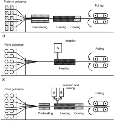
Figure 18. Sketches of different pultrusion processes: (a) non-reactive pultrusion of thermoplastic performs; (b) reactive pultrusion for thermoset composites; (c) reactive pultrusion for thermoplastic
composites [104]
According to Table 6 [103] application of thermosetting resins are the simplest from process control point of view compared to the other methods. Die temperature profile is to be kept constant beside the constant process speed. This ensures proper crosslinking and constant product quality. During thermosetting pultrusion (Figure 19) fibers (a) are led through guides into a resin bath (c) to impregnate with a thermoreactive resin, usually unsaturated polyester. The impregnated fiber structure is led into a heated die (d) which forms the composite and where the crosslinking reaction starts. Then comes the post curing (e) unit which is preheated and crosslinking is completed there. Thereafter the puller (f) is found which sets up process speed and is usually a reciprocating caterpillar device. After this the profile is cut by a pneumatically moved cutoff saw [102].
Thermoset pultrusion is widely used all over the world owing to its high productivity and constant good quality of these products. Construction profiles, antenna radomes, cable ducts, linings and any other constant cross section profiles are produced by this method [105].
![Figure 5. Graphene as a building material of all other dimensionalities: a – fullerenes; b – carbon nanotube; c – graphite; d – graphene nanoplatelets, SEM image [42]](https://thumb-eu.123doks.com/thumbv2/9dokorg/1311496.105487/15.892.146.785.364.641/graphene-building-material-dimensionalities-fullerenes-nanotube-graphite-nanoplatelets.webp)
![Figure 11. Polymerization of CBT160 in function of time and temperature (a); Time-Temperature- Time-Temperature-Conversion diagram for isothermal conditions (b, modeled values) [46]](https://thumb-eu.123doks.com/thumbv2/9dokorg/1311496.105487/20.892.140.756.532.758/polymerization-function-temperature-temperature-temperature-conversion-isothermal-conditions.webp)
![Figure 12. Necessary drying times for different forms of CBT with different methods [46]](https://thumb-eu.123doks.com/thumbv2/9dokorg/1311496.105487/23.892.266.649.234.488/figure-necessary-drying-times-different-forms-different-methods.webp)
![Figure 16. Intervall hot press to produce composite sheets with pCBT matrix [46]](https://thumb-eu.123doks.com/thumbv2/9dokorg/1311496.105487/31.892.229.688.732.1026/figure-intervall-press-produce-composite-sheets-pcbt-matrix.webp)
![Figure 22. Schematic of electrostatic impregnation process. Water misting is necessary to make glass fibers conductive [116]](https://thumb-eu.123doks.com/thumbv2/9dokorg/1311496.105487/36.892.194.716.280.453/figure-schematic-electrostatic-impregnation-process-misting-necessary-conductive.webp)