Ultrasonic welding of all-polypropylene composites Kiss Z., Temesi T., Bitay E., Bárány T., Czigány T.
Accepted for publication in Journal of Applied Polymer Science Published in -0001
DOI: 10.1002/app.48799
Powered by TCPDF (www.tcpdf.org)
Ultrasonic Welding of All-Polypropylene Composites
Zoltán Kiss, Tamás Temesi, Enikő Bitay, Tamás Bárány, Tibor Czigány
*Dr. Zoltán Kiss, Department of Polymer Engineering, Faculty of Mechanical Engineering, Budapest University of Technology and Economics. Műegyetem rkp. 3., H-1111 Budapest, Hungary.
Tamás Temesi, Department of Polymer Engineering, Faculty of Mechanical Engineering, Budapest University of Technology and Economics. Műegyetem rkp. 3., H-1111 Budapest, Hungary.
Dr. Enikő Bitay, Faculty of Technical and Human Sciences, Sapientia Hungarian University of Transylvania. 540485 Târgu-Mureş, Op. 9., Cp. 4., Romania.
Dr. Tamás Bárány, Department of Polymer Engineering, Faculty of Mechanical Engineering, Budapest University of Technology and Economics. Műegyetem rkp. 3., H-1111 Budapest, Hungary.
Prof. Dr. Tibor Czigány, Department of Polymer Engineering, Faculty of Mechanical Engineering, Budapest University of Technology and Economics. Műegyetem rkp. 3., H-1111 Budapest, Hungary.
Prof. Dr. Tibor Czigány, MTA–BME Research Group for Composite Science and Technology, Műegyetem rkp. 3., H-1111 Budapest, Hungary.
* Corresponding author, e-mail: czigany@eik.bme.hu
Keywords: all-polymer composites, polypropylene, ultrasonic welding, shear strength
Abstract
In this study, the mechanical properties of ultrasonic welded lap joints of all-polypropylene composite (APPC) were investigated and compared to the interlaminar properties of the composite sheet itself. The process control parameter was welding time: welded samples were prepared with an ultrasonic welding machine in the 0.1–1.0 second time range. In most cases, the shear strength of the welded samples exceeded that of the unwelded APPC. Although it was found that during the ultrasonic welding process, the reinforcing tapes partially melted in the welding zone, the seam remained strong enough since the heat released and the pressure applied during the welding process further improved the consolidation of the APPC layers.
1. Introduction
Polypropylene (PP) is one of the most frequently used polymer materials, owing to its low price, good processability and mechanical properties. [1-3] In order to achieve mechanical properties similar to those of engineering materials, neat PP has to be reinforced. [4-7] The most frequently used reinforcement is glass fibre (GF), which can improve both the modulus and the strength of the matrix material. The main problem is that the adhesion of glass fibres to the strongly non-polar PP is poor, therefore fibres must be treated with a sizing material and/or a coupling agent needs to be added to the PP matrix or copolymerization of the PP material may be necessary. [8, 9] Another disadvantage of GF reinforcement is during the mechanical recycling of reinforced polymers, glass fibres become too fragmented, and lose their reinforcing ability.
[10] Due to environmental concerns, improving the recyclability of composite materials is already in the EU’s automotive industrial regulations. [11] Therefore easily recyclable and reprocessible all-polymer composite materials are increasingly used; they exhibit similar mechanical properties (when the difference in density is considered) to composites with traditional (for example glass or carbon fibre) reinforcements. [12-17]
In all-polymer composites, both the reinforcement and the matrix material belong to the same material family, therefore the mass of the all-polymer composite can be as much as 30%
lower than the mass of a glass fibre-reinforced composite with the same amount of reinforcement. Three main methods are generally used for the production of all-polymer composite materials: hot compaction, consolidation of coextruded tapes and film stacking. [18-
20] Many papers focus on the mechanical properties of various all-polymer composites and the consolidation process of the matrix and fibre components. [16, 17, 21-26] Studies have also
confirmed that all-PP composites can be prepared by injection moulding. [21, 24] There are numerous uses of self-reinforced and all-polymer composites in the automotive industry, especially as interior components. [27]
Plastics can be joined with several methods, ranging from snap fits through adhesive bonding to welding processes. [28-32] Ultrasonic welding is one of the most frequently used welding technologies, especially in the electric, electronic and automotive industries. [33] A major advantage of this technology is that it is fast, economic to use in large series production and can also be easily controlled and automated. [34] When mechanical vibrations, produced by the ultrasonic welding machine, reach a thermoplastic polymer, sinusoidal standing waves are generated inside the material. The inherent energy of the vibrations is transformed into heat during welding in two ways: at the start of the welding process, heat is generated on the border between the two overlapped specimens because of friction. The amount of heat generated depends on the surface roughness and friction coefficient between the specimens. With enough heat and friction, the geometrical features on the surface (i.e. the surface roughness) melt and disappear. Heat is also generated when vibrations are dampened because of the resistance of primary chemical bonds between atoms, molecules and polymer chains. Secondary bonds can also break, promoting chain movement at elevated temperatures. [35]
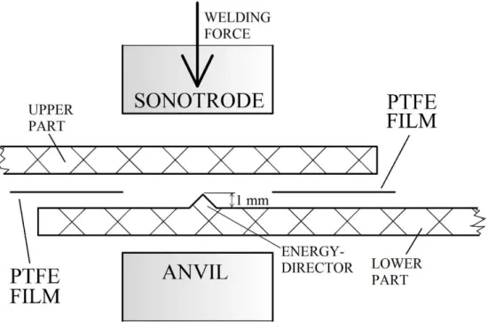
During ultrasonic welding, the parts must be firmly clamped in a controllable manner, for which an anvil (a counter-support under the welded parts) is used. Mechanical vibrations are transmitted to the seam by the so-called sonotrode, which also clamps the welded parts together (Figure 1). [34, 35] The quality of the welded seam can be considerably improved with an energy director, which is a geometrical feature on the welded product. The energy director transforms the plane-to-plane contact of the welded surfaces into plane-to-linear or even plane-to-point contacts, concentrating the energy of ultrasonic vibrations and thus increasing heat release rates.
The design and shape of the energy director greatly determines the strength of the welded joint and the transformation of ultrasonic energy to heat. [36] In applications where hermetic seals must be formed, a solid joint can hardly be achieved without the use of an energy director.
Composites with a thermoplastic matrix can also be joined by ultrasonic welding. [37]
In this study, the mechanical properties of ultrasonic-welded APPC lap joints welded with various welding times, with and without an energy director were analysed and compared to the interlaminar properties of the all-PP composite laminates with mechanical and optical tests.
2. Materials and Methods
The matrix material of the APPC sheets was a 0.18 mm thick film extruded from Tipplen R351 PP copolymer pellets (MFI=8.5 g/10 min (2.16 kg at 230 °C); manufacturer: MOL Petrolkémia Zrt., Tiszaújváros, Hungary). The reinforcement was a woven fabric (manufacturer: Stradom S.A., Częstochowa, Poland) composed of highly stretched, split PP tapes with a nominal weight of 180 g/m2. The reinforcing tape had a melting temperature of Tm=172.4 °C (determined by DSC in accordance with ISO 11357-4, in the temperature range of -100…+250 ºC, at a heating rate of 7.5 ºC/min in 50 ml/min N2 flow), and a tensile strength of 465±32 MPa (measured on five samples cut out from a single tape). The matrix films (7 layers) and the reinforcing woven fabrics (6 layers) were assembled with a cross-ply lay-up to make the resulting sheets orthotropic. 2 mm thick composite sheets with a base area of 350 x 350 mm were prepared by film-stacking in a heated press with the following parameters: the sheets were held at 167 ºC for 30 seconds at atmospheric pressure in the closed press, then they were compression moulded at 6 MPa pressure for 90 seconds, followed by cooling under 6 MPa to 50 ºC at a cooling rate of 7.5 ºC/min. Nominal reinforcement content was 50 wt%. Specimens with a triangle-shaped energy director (Figure 1) were also manufactured with the same process parameters with a mould with a corresponding triangle-shaped groove. As there is no ideal angle for the energy director published in the literature, the following parameters were used:
90º main angle and 1 mm height, as used in other publications. [20, 22] 25 mm wide strips were cut from the APPC sheets for mechanical testing and welding.
Welding experiments were done on a Herrmann Ultraschalltechnik HiQ Evolution Speed Control ultrasonic welding machine. A catenoidal sonotrode with a 70x11 mm flat welding surface, together with a flat anvil was used. The APPC specimens were clamped together in an overlapped position and were welded as shown in Figure 2. The vibration amplitude transformation constant of the sonotrode was 1:2.6, while the amplification factor of the booster amplifier was 1:1.25, meaning that the amplitude of the vibrations was 39 µm. The welding frequency was 20 kHz.
The welding machine was able to control the welding process in various modes, i.e. time mode, energy mode, power consumption mode and displacement mode. We selected time control mode as it is the simplest and is commonly used in the industry. Welding was performed in the range of 0.1-1 seconds, with a clamping force of 300 N, which was found to be optimal in our preliminary experiments. After the vibrations stopped, the sonotrode clamped the seam for 2 more seconds with 300 N, therefore it was under pressure during the cooling period. A
clamping force of 300 N set on the welding machine translated into 1.1 MPa of pressure at the overlapping area of the welded sheets.
We compared the mechanical properties of the APPC sheet and the welded joints by lap shear tests and determined the interlaminar strength of the composite laminates with a double- notched shear test according to ASTM D3846, on five specimens cut and prepared from the APPC sheets. Test speed was 5 mm/min for both mechanical testing methods, as recommended by the ASTM D3846 standard. Mechanical tests were performed on a Zwick Z020 type universal testing machine at room temperature. Cross-sections of the seams were examined with an Olympus BX51 optical microscope.
Figure 3 shows the geometry of the tested specimens. Figure 3/a shows the specimen cut from the APPC sheet, prepared for the double-notched in-plane shear test, during which the shear stress between the reinforcement and matrix layers were measured. Figure 3/b shows the lap shear test arrangement of the welded joints. In this case, both tensile, shear and torsion forces loaded the specimen, with shear force being the dominant loading component. The ultimate lap shear strength (ULSS) of the specimens was calculated.
3. Results and Discussion
3.1. Shear Strength of the Raw Material and the Welded Joint
At first, we welded the APPC specimens together without inserting a PTFE film between them. Then we examined the joints with an Olympus optical microscope and found that the sheets were welded together not only in the area between the sonotrode and the anvil but also further away from the compressed surface. Thus, we could not calculate the exact strength of the joint as the area of the welded surfaces differed from specimen to specimen. To eliminate this effect, we placed a thin film made of PTFE between the APPC sheets during welding so that the width of the seam was equal to the width of the sonotrode (11 mm), as shown in Figure 1 and 3. This way, we were able to significantly reduce the standard deviation of the measured data.
The strength of the lap joints is described by the ratio of the force needed for failure divided by the overlapping surface area. 5 samples were welded and measured for each welding time value. The maximum shear strength of welded specimens (8.5±0.4 MPa) was higher than the 4.8±0.8 MPa measured for the APPC sheet. Furthermore, interlaminar shear strength was approximated or even surpassed by the shear strength of the welded joint in almost the entire
welding time range: the strength of the joints became significantly lower only in the case of very short (0.1-0.2 s) welding times.
Figure 4 shows that there was an optimal welding time range, below which weld shear strength decreased, along with the reproducibility of the welded joint (as can be seen through the increase in the standard deviation of strength values). With this welding arrangement, the greatest shear strength (approximately 8.5 MPa) was achieved with a welding time of 0.5-0.7 s. The reinforcing tapes also partly melted and recrystallized, thus adhesion between the matrix material and the reinforcing tapes also changed. The shear strength increased and the trendline of average values resembled a saturation curve until 0.7 s welding time. When welding time was longer than 0.7 s, the matrix material of the laminates melted and was partly pushed out from between the sonotrode and the anvil, flash was formed near the seam and the sonotrode made a distinct indentation, thus a weak region was formed in the material. In these cases, the joints failed near the seam, in the welding zone (WZ), by tensile fracture of the APPC, thus we could not determine the shear strength of the specimens (the characteristic failure modes of the specimens as a function of welding time are noted in Figure 4).
3.2. Shear Strength of the Welded Joint Manufactured with an Energy Director
Shear strength was slightly greater when an APPC specimen with an energy director and a simple APPC specimen were welded together (Figure 1) compared to the instances when APPC sheets without an energy director were welded together. A thin PTFE film was also placed between the APPC specimens, so that the width of the seam was equal to the width of the sonotrode (11 mm), and shear strength could be compared with the shear strength of APPC specimens without an energy director. Figure 5 shows that above the 0.7 sec welding time threshold, the shear strength of the welded joint exceeded 9.0 MPa. However, above the 1.0 s welding time threshold, the sonotrode made an indentation on the surface of the welded sheets (Figure 6/d and 6/e) and a weak region near the edge of the seam was formed.
The characteristic failure mode of the welded samples was tape-matrix delamination when the welding time was below 0.9 s. Up to 0.8 s welding time, there were no visible marks or defects left by the sonotrode on the surfaces of the welded sheets (Figure 6/a and Figure 6/b).
Figure 6/c shows a side view of the lap joint (welding time: 0.7 s) after the shear test. Both the matrix and the reinforcing materials of the APPC partially melted and recrystallized, causing interfacial properties to change and improving the shear strength of the joints. At a welding time of 1.0 s (Figure 6/d and 6/e), the sonotrode significantly sank into the material of the welded sheets, leaving an indentation at the edge of the seam. As a result, the seam was thinner
and flash was pushed out perpendicularly to the longitudinal axis of the specimens, while the joint failed at the edge of the seam by tensile fracture. Because of this, we could not determine the shear strength values of any specimens welded with more 0.9 s welding time.
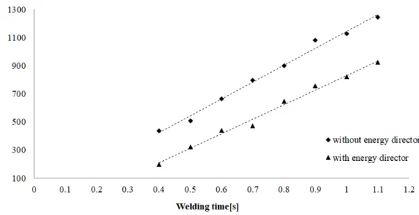
The effect of the energy director on the quality of the seam was reflected not only in shear strength, but also in the welding energy measured by the ultrasonic welding machine. Figure 7 shows that both with and without an energy director, the energy needed to complete the welding process increased with welding time in a linear manner. However, when an energy director was used, significantly less energy was consumed, and the joint had better strength. This was caused by the energy director, which concentrated the heat generated from ultrasonic energy into a smaller heat-affected zone (HAZ). As a result, less energy was needed for the same effect and there were also fewer microstructural changes in the matrix material in the vicinity of the seam.
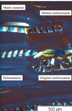
Figure 8 shows a transmitted light microscopy image of the cross-section of a welded seam where an energy director was used. The border between the two welded sheets completely disappeared. The reinforcing tapes at the lower and upper part of the figure (grey and black quasi-horizontal lines) are relatively intact but in the centre of the image, the tapes have completely melted: this was caused by a highly concentrated heat build-up in the vicinity of the energy director. In the polarized light microscopy image in Figure 9, the typical damage types of the APPC sheets can be seen: with long welding time, the reinforcing material can break into shorter pieces or melt and recrystallize even without the use of an energy director. Furthermore, tape-matrix debonding and delamination can also occur. These defects act as starting points for cracks, impairing the mechanical properties of the welded samples.
4. Conclusions
Shear tests were performed on all-polypropylene composite (APPC) sheets and ultrasonic welded APPC specimens cut from the same laminates (manufactured with and without an energy director) according to ASTM D3846, to examine the strength of the laminates and the joints. An ultrasonic welding machine was used in time-control mode (with a welding time of 0.1-1.0 second) and welded sheets had greater strength than the interlaminar shear strength of the unwelded APPC sheets. This can be explained by the improved tape-matrix connection, due to the combined effect of heat generated by ultrasonic vibrations and the applied welding pressure. It was also found that an energy director improves the quality of welding of APPC sheets, as it slightly improves the strength and reproducibility of the seams. It also decreases the energy needed for welding. When welding time was below or equal to 0.6-0.7 seconds, the sonotrode and the anvil left practically no marks on the surfaces of the welded sheets, and
therefore joints had good mechanical properties and were aesthetic. This light-weight composite structure (and the ultrasonic welding process used to join these parts together) has promising potential applications in the vehicle industry (as dashboard and bumper elements) and in other industries too (in the energy sector, in sports goods, etc).
Conflict of interest
The authors state that there is no conflict of interest.
Acknowledgements
The authors are grateful to Herrmann Ultraschalltechnik GmbH & Co. KG for providing the ultrasonic welding machine.
Funding
This work was supported by the National Research, Development and Innovation Office of Hungary (Grant number: NVKP_16-1-2016-0046), the ÚNKP-18-3 New National Excellence Program of the Ministry of Human Capacities of Hungary under grant no. ÚNKP-18-3-I-BME- 183, by the Higher Education Excellence Program of the Ministry of Human Capacities in the frame of Nanotechnology research area of Budapest University of Technology and Economics (BME FIKP-NANO) and by the National Research, Development and Innovation Fund (TUDFO/51757/2019-ITM, Thematic Excellence Program).
References
[1] Karger-Kocsis J. (editor), Polypropylene - an A-Z reference, Springer- Science+Business Media, B.V, Dordrecht, The Netherlands, 1999.
[2] Karian H. G. (editor), Handbook of Polypropylene and Polypropylene composites, Marcel Dekker Inc., New York, NY, USA, 2003.
[3] Karger-Kocsis J., Barany T. (eds), Polypropylene Handbook - Morphology, Blends and Composites, Springer International Publishing, New York, NY, USA, 2019.
[4] J. L. Thomason, G.E. Schoolenberg, Composites 1994, 25(3), 197.
[5] J. Szakács, L. Mészáros, Period. Polytech., Mech. Eng. 2017, 61(1), 74.
[6] A. Dong, F. Li, X. Fan, Q. Wang, Y. Yu, P. Wang, J. Yuan, A. Cavaco-Paulo, J. of Thermoplast. Compos. Mater. 2017, 31(4), 483.
[7] R. Chollakup, H. Askanian, F. Delor-Jestin, J. of Thermoplast. Compos. Mater. 2016, 30(2), 174.
[8] J. Karger-Kocsis, T. Harmia, T. Czigány, Compos. Sci. Tech. 1995, 54, 287.
[9] G. Acik, E. Sey, M. A. Tasdelen, Express Polym. Lett. 2018, 12(5), 418.
[10] V. Goodship (editor), Management, recycling and reuse of waste composites.
Woodhead Publishing, UK, 2009.
[11] Directive 2000/53/EC of European Parliament and of the Council of 18 September 2000.
[12] J. Andrzejewski, P. Przyszczypkowski, M. Szostak, Mater. Des. 2018, 153, 273.
[13] S. Fakirov, Advanced Industrial and Engineering Polymer Research 2018, 1(1), 40.
[14] L. Han, B. Wang, Y. Dai, Y. Zhang, H. Xu, X. Sui, L. Zhang, Y. Zhong, Z. Mao, Compos. Sci. Tech. 2018, 165, 331.
[15] K. Somord, K. Somord, O. Suwantong, C. Thanomsilp, T. Peijs, N. Soykeabkaew, Nanocomposites 2018, 4(3), 102.
[16] D. Vadas, Á. Kmetty, T. Bárány, G. Marosi, K. Bocz, Polym. Adv. Tech. 2018, 29(1), 433.
[17] S. Goutianos, L. Van der Schueren, J. Beauson, Composites, Part A 2019, 117, 169.
[18] Á. Kmetty, T. Bárány, J. Karger-Kocsis, Progr. Polym. Sci. 2010, 35(10), 1288.
[19] I. M. Ward, P. J. Hine, Polymer 2004, 45, 1413.
[20] N. J. Capiati, R. S. Porter, J. Mater. Sci. 1975, 10, 1671.
[21] Á. Kmetty, T. Tábi, J. G. Kovács, T. Bárány, Express Polym. Lett. 2013, 7(2), 134.
[22] J. C. Chen, C. M. Wu, F. C. Pu, C. H. Chiu, Express Polym. Lett. 2011, 5(3), 228.
[23] Á. Izer, T. Bárány, Express Polym. Lett. 2010, 4(4), 210.
[24] Á. Kmetty, T. Bárány, J. Karger-Kocsis, Compos. Sci. Tech. 2012, 73, 72.
[25] C. M. Wu, P. C. Lin, R. Murakami, Express Polym. Lett. 2017, 11(10), 820.
[26] A. Imran, S. Qi, C. Yan D. Liu, Y. Zhu, G. Yang, Composite Structures 2018, 204, 288.
[27] J. Rotheiser, Joining of Plastics - Handbook for Designers and Engineers, Carl Hanser Verlag, Munich, Germany, 1999.
[28] D. Biermann, J. Gausemeier, H-P. Heim, S. Hess, M. Petersen, A. Ries, T. Wagner, Production Engineering 2015, 9(3), 405.
[29] B. Patham, P. H. Foss, Polym. Eng. Sci. 2011, 51(1), 1.
[30] A. Yousefpour, M. Hojjati, J-P. Immarigeon, J. Thermoplast. Compos. Mater. 2016, 17(4), 303.
[31] S. Gao, C. S. Wu, G. K. Padhy, Sci. Technol. Weld. Joining 2018, 23(8), 693.
[32] H. A. Derazkola, A. Simchi, Sci. Technol. Weld. Joining 2017, 23(3), 209.
[33] J. Puiggali, Express Polym. Lett. 2018, 12(4), 284.
[34] M. J. Troughton, Handbook of Plastics Joining A Practical Guide, 2nd Edition, William Andrew Inc., Norwich, NY, USA, 2008.
[35] A. Benatar, in Power Ultrasonics (Eds: J. A. Gallego-Juárez, K. F. Graff), Cambridge, UK: Woodhead Publishing, Cambridge, UK, 2015.
[36] K. S. Suresh, M. R. Rani, K. Prakasan, R. Rudramoorthy, J. Mater. Process. Technol.
2007, 186(1-3), 138.
[37] Y. Luo, Z. Zhang, X. Wang, Y. Zheng, Microelectron. Eng. 2010, 87(11), 2429.
Figure 1. Side view of the welding configuration with the location and geometry of the energy director and the polytetrafluorethylene (PTFE) film
Figure 2. Arrangement of the overlapping sheets and the welding configuration
a) b)
Figure 3. Side view of the test specimens used in the shear strength tests.
a) Test specimen made of APPC raw material, prepared according to ASTM D3846, b) welded sample prepared for the lap shear strength test.
Figure 4. Shear strength of lap joints prepared without an energy director and the characteristic failure mode of the welded joints as a function of welding time
Figure 5. Shear strength of the test specimens welded with an energy director and the characteristic failure mode of the welded joints as a function of welding time
e
Figure 6. Side view of the samples a. During welding
b & c. After welding (welding time < 0.7 s) d & e. After welding (welding time > 0.7 s) a
b d
c
Figure 7. The energy necessary for welding with and without an energy director, as a function of welding time
Figure 8. Transmitted light microscopy image of the cross-section of the seam welded with an energy director. The central, circumscribed part shows the melted zone produced by the
energy director.
White areas: matrix material, black or grey areas: reinforcing tapes
Figure 9. Polarized light microscopic image of the cross-section of a seam welded without an energy director
Short biographical notes of authors Zoltán Kiss
Dr. Zoltán Kiss received his PhD degree from the Budapest University of Technology and Economics (BME) in 2011. He has a strong background in joining and welding processes, especially in those used to join polymer parts together: in his thesis, Zoltán Kiss proved the applicability of joining polymer parts with the friction stir welding technology. His research interests also extend to the field of medical technology and biomechanics. He is the author of more than 20 publications with more than 100 independent citations, has an impact factor of more than 14 and an h-index of 4. https://orcid.org/0000- 0003-3069-1773
Tamás Temesi
Mr. Tamás Temesi earned his master’s degree in 2016 in mechanical engineering at the Budapest University of Technology and Economics (BME). He is currently a PhD student at the Department of Polymer Engineering. He has a background in the joining and welding of polymer structures, and in the area of manufacturing metal-polymer hybrid structures using laser welding, which is also the subject of his PhD thesis. He is the author of 2 publications and 3 proceedings. https://orcid.org/0000-0002-4869- 7498
Enikő Bitay
Dr. Enikő Bitay received her PhD at the Technical University of Cluj-Napoca in the field of materials engineering in 2003. She is presently associate professor at the Sapientia Hungarian University of Transylvania and an external member of the Hungarian Academy of Sciences. Her research topic covers the welding and laser marking of metals and biopolymer composites. She (co-)authored more than 180 publications in Hungarian, Romanian and English in books, international journals and conference papers. https://orcid.org/0000-0003-2991-7333
Tamás Bárány
Dr. Tamás Bárány received his PhD from the Budapest University of Technology and Economics (BME) in 2004. His main research topic is the development and examination of thermoplastic elastomers and self-reinforced and all-polymer composites and also the recyclability and reusability of polymer materials. He is also the head of the Department of Polymer Engineering at BME. He is the author of more than 60 publications with more than 1000 independent citations, has an impact factor of 122 and an h-index of 19. https://orcid.org/0000-0002-9196-7852
Tibor Czigány
Tibor Czigány is currently a professor at the Department of Polymer Engineering at the Budapest University of Technology and Economics (BME). He received his mechanical engineering master’s degree in 1988 and his PhD in 1997 from BME. He is a full member of the Hungarian Academy of Science (MTA) and leader of the MTA-BME Research Group for Composite Science and Technology.
His research focuses on polymer engineering, composite materials and materials testing. He is the author of more than 250 papers and proceedings with more than 4000 independent citations, while his cumulative impact factor is almost 200 and his h-index is 36. https://orcid.org/0000-0002-5138-0141