Applied Catalysis A, General 620 (2021) 118155
Available online 20 April 2021
0926-860X/© 2021 The Author(s). Published by Elsevier B.V. This is an open access article under the CC BY license (http://creativecommons.org/licenses/by/4.0/).
Investigation of Ti-Mo mixed oxide-carbon composite supported Pt electrocatalysts: Effect of the type of carbonaceous materials
Irina Borb ´ ath
a,*, Emília T ´ alas
a, Zolt ´ an P ´ aszti
a, Krist of Zelenka ´
a, Ilgar Ayyubov
a, Khirdakhanim Salmanzade
a, Istv ´ an E. Saj o ´
b, Gy orgy S ¨ ´ afr ´ an
c, Andr ´ as Tompos
aaResearch Centre for Natural Sciences, Institute of Materials and Environmental Chemistry, E¨otv¨os Lor´and Research Network (ELKH), Magyar tud´osok k¨orútja 2, H- 1117, Budapest, Hungary
bUniversity of P´ecs, Szent´agothai Research Centre, Ifjúsag u. 20. H-7624, P´ ´ecs, Hungary
cCentre for Energy Research, Institute for Technical Physics and Materials Science, E¨otv¨os Lor´and Research Network (ELKH), Konkoly-Thege M. út 29-33, H-1121, Budapest, Hungary
A R T I C L E I N F O Keywords:
Composite materials TiMoOx
Graphite oxide Pt electrocatalysts Long-term stability test
A B S T R A C T
Ti0.8M0.2O2-C composites are novel supports for Pt-based fuel cell electrocatalysts with enhanced stability and CO-tolerance. In this work the effect of the type of the carbonaceous material (Vulcan XC-72, Black Pearls 2000 and graphite oxide) as well as the mixed oxide/carbon ratio was explored on the structure and the electro- chemical performance of the supports and the related electrocatalysts. The composites were prepared by opti- mized routes tailored to the special features of the carbonaceous materials.
Better CO tolerance was obtained on the catalysts containing 75 wt.% of the Ti0.8Mo0.2O2 as compared to those with high carbon content. However, the more homogeneous microstructure of the catalysts with high carbon content (75 wt.%) was identified as the key for enhanced long-term stability. Considering also the fact that the high oxide content of the catalyst increases the cell resistance, the Black Pearls-based Pt electrocatalysts with Ti0.8Mo0.2O2/C =25/75 ratio seem to be the most promising.
1. Introduction
Fuel cells convert chemical energy of hydrogen-rich fuels into elec- tricity without emission of greenhouse gases. An estimated 30 % of the price of a Polymer Electrolyte Membrane (PEM) fuel cell belongs to the electrocatalysts, which requires high amounts of platinum as the active element [1].
The key requirements for prospective electrocatalysts in PEM fuel cells involve [2]: (i) high stability in the anticipated pH/potential win- dow, (ii) high resistance against electrochemical corrosion, (iii) good electronic and proton conductivity, (iv) high specific surface area, (v) appropriate porosity for mass transfer of liquid fuels or oxygen gas and the minimization of water flooding in electrodes, and (vi) strong inter- action between the Pt nanoparticles and the support.
At present, Pt/C catalysts represent the most widespread choice for PEM fuel cells even if they are prone to eletrocorrosion under the working conditions of the cell, especially during start/stop cycles. The main reason for the catalyst degradation is that the cathode potential can locally rise to values up to 1.5 V during the initial phase when the
fuel gas purging is insufficient, causing aging of the carbon support as well as the platinum nanoparticles [3,4]. Corrosion results in either Pt dissolution or oxidation of the carbon support leading to detachment, Ostwald ripening and agglomeration of platinum nanoparticles [5–7].
Another issue of the traditional Pt/C catalysts is their sensitivity towards CO poisoning [8,9]. It is therefore important to explore alternative materials that can provide improved stability and increased CO tolerance.
A novel class of TiO2 supported Pt electrocatalysts with improved stability was developed to overcome the inherent limitations of the traditional Pt/C catalysts [10,11]. It has been demonstrated that elec- trocatalytic activity, CO tolerance and stability of platinum catalyst can be also substantially improved by doping titania with oxophilic metals such as W, Mo, Sn and Ta [12–15], but electronic conductivities of these materials are still substantially lower than those of carbon catalyst supports.
On the other hand, active carbon can be regarded as a locally graphitic material with long range disorder. The graphitic nature en- sures quite high conductivity (e.g., Vulcan XC-72: 4.5 S/cm, Black Pearls
* Corresponding author at: H-1519 Budapest, P.O. Box 286, Hungary.
E-mail address: borbath.irina@ttk.hu (I. Borb´ath).
Contents lists available at ScienceDirect
Applied Catalysis A, General
journal homepage: www.elsevier.com/locate/apcata
https://doi.org/10.1016/j.apcata.2021.118155
Received 30 October 2020; Received in revised form 5 March 2021; Accepted 7 April 2021
2000: 2.2 S/cm [16]). Materials composed of Pt nanoparticles (NPs), TiO2 and carbon materials are identified as efficient electrocatalysts since they combine the high conductivity of carbon and corrosion resistance of the oxide with the synergistic effect between metal oxides and Pt [17–21]. Composite support materials, such as TiO2-C also show improved stability in accelerated aging tests [22,23].
Furthermore, it is established that functionalization of the carbona- ceous support has a beneficial effect on the deposition of the metal oxide. The common procedure of functionalization consists of treatment with H2O2, citric acid, HNO3, or a mixture of HNO3 and H2SO4 acids [24–26]. Functionalizing the carbonaceous support with glucose, HNO3
or mixture of HNO3-H2SO4 acids facilitates the growth of uniform layer of very small TiO2 NPs on the carbon surface [27,28]. Results obtained on Pt/TiO2/C catalysts, prepared using glucose doped Vulcan XC-72, show superior oxygen reduction reaction (ORR) activity and better durability during accelerated stress tests [29].
Recently, new types of carbonaceous materials like carbon nano- tubes (CNT), graphene, reduced graphene oxides (rGO) has been re- ported to provide exciting properties to TiO2-carbonaceous composites due to their special electronic structure. Exfoliated graphite oxide (GO) with abundant oxygen-containing functional groups is a relatively cheap, promising new carbonaceous starting material for composites.
These functional groups [30] provide reactive and anchoring sites for nucleation and growth of nanomaterials when TiO2 is in situ prepared in the presence of GO [31]. The key point for usage of GO is its exfoliation also known as delamination. Slightly basic conditions can help to ach- ieve large degrees of dispersion, because GO layers decorated with functional groups with the same negative charge repel each other [32].
The rapid thermal exfoliation of GO leads to rGO, which contains a strongly defective single-layer and low-layer graphene sheet and can have a specific surface area of up to 800 m2/g [33].
Huge amount of work deals with the preparation and characteriza- tion of GO derived TiO2–carbonaceous material composites on the field of photo- [34–37] and electrocatalysis [38–40]. A Pt/graphene-TiO2 catalyst prepared by a microwave-assisted solvothermal method exhibited a significant improvement in activity and stability towards the ORR compared with Pt/C [41]. Enhanced methanol electrooxidation performance in single fuel cell tests was demonstrated on Pt/graphe- ne-TiO2 hybrid catalysts synthesized by one-pot solvothermal method [42]. A unique electrocatalyst composed of a dimensionally stable anode of graphene oxide and rGO combined with RuO2 and TiO2 nanoparticles has also been synthesized [43]. In the above work rGO was obtained by hydrazine reduction of GO prepared by the modified Hummers’s method from graphite [43]. In fact, a significant part of the works on TiO2-g- raphene composites has reported the use of rGO from GO [30].
Our concept of non-noble metal-doped TiO2 – active carbon com- posite supports is based on the idea of bringing together the excellent stability and nanoparticle-stabilizing ability of TiO2 with the good co- catalytic properties of doping metal (M =W, Mo) and with the good conductivity and large surface area of active carbon in a unique material system. We demonstrated [44,45] that exclusive incorporation of the doping metals into substitutional sites of the TiO2 lattice is a necessary requirement for practical realization of a mixed oxide – active carbon composite as a support for electrocatalysts in PEM fuel cells. Under such circumstances the TiO2 lattice protects the doping metal atoms from dissolution, while they can still provide CO tolerance.
In the synthesis of novel TiO2-rutile-based Ti(1-x)MxO2-C multifunc- tional composite support materials with predominant Pt-mixed oxide interactions [46] the focus was on diversity of compositional and syn- thetic variables. Slightly different multistep sol-gel-based synthesis procedures were optimized for the Mo- and the W-doped composites.
Our previous studies also revealed that (i) complete incorporation of the oxophilic metal can be achieved only into the TiO2-rutile lattice and (ii) the formation of the rutile phase TiO2 nucleus before the high-temperature treatment is prerequisite [47,48]. We demonstrated that the catalytic properties of the system are mainly determined by the
interaction between Pt and doping transition M metals (M =W, Mo); the electrochemical studies of the Mo-doped TiO2 - active carbon composite supported Pt catalysts were completed by model studies during which Mo was electrochemically deposited onto Pt electrodes [49].
The electrochemical stability tests revealed that the degradation rate of the composite supported electrocatalysts was much smaller than that of the Pt/C and PtRu/C catalysts [44,47,50]. Better performance of the Pt/Ti0.7M0.3O2-C (M =W, Mo) catalysts in a single cell test device using hydrogen containing 100 ppm CO compared to the reference Pt/C and PtRu/C catalysts was also demonstrated [51].
In case of Mo-doped composite supports an upper limit for Mo dopant incorporation exists around 20–30 % [48]; dopant material used in excess of this amount segregates in form of a separate MoO2 phase. A correlation was found between the extent of Mo incorporation and the stability of the electrocatalysts: composites with lower amount of segregated Mo-oxides showed better stability. Thus, Ti0.8Mo0.2O2–C composites with Ti/Mo =80/20 atomic ratio was used as an optimal composition. In our recent study [52] good CO tolerance of the catalyst was demonstrated by investigation of the impact of catalyst loading, pressure and composition of reformate gas on the PEM fuel cell perfor- mance of Ti0.8Mo0.2O2–C composite supportedanode catalyst with 20 wt.% Pt content. We found [52] that dilution of hydrogen with CO2 and CH4 in reformate gas had negligible negative impact on the fuel cell performance. Switching gas composition between hydrogen and refor- mate shows recovery of potential after CO poisoning.
However, it is known that high oxide content in the anode catalyst layer can result in some increase of the internal resistance of the cell and as a consequence in a performance loss [53]. Thus, upon the preparation of the oxide-containing composite supports the main goal is to deter- mine an optimal ratio between the oxide and the active carbon in the composites. In line with the requirement for lower cell resistance, literature data seems to favor composites with smaller oxide content.
Unfortunately, it appears that the synthesis method used for the prep- aration of TiO2 coating over carbon support has the most important influence on the electrochemical properties of the catalysts; depending on the selected synthesis method the optimal content of TiO2 in Pt/TiO2-C catalysts varies from 10 [54] to 40 wt.% [55] of oxide in various studies. In the Pt-Pd/C-TaNbTiO2 catalyst, the C/TaNbTiO2 ratio in the carbon-hybrid support 75/25 was chosen as the optimal compo- sition, which, along with excellent electrochemical properties, had good conductivity and high specific surface area [56].
Our aim in this study is to explore the behavior of electrocatalysts prepared on Ti0.8M0.2O2-C composite supports with different types of carbonaceous backbones and with varying mixed oxide/carbon ratio. In order to minimize the effect of the preparation route, our established method was optimized for synthesis of composites with different mixed oxide/carbon ratio using GO, Vulcan XC-72, unmodified and function- alized Black Pearls 2000 as carbon materials, while preserving the rutile structure of Mo-doped TiO2. Then using a combination of structural, spectroscopic and electrochemical methods we analyzed the effect of the mixed oxide/carbon ratio and the different carbon materials in the support on the stability and functionality of the Pt electrocatalysts, in order to determine the optimal composition for the composite supported catalyst with 20 wt.% Pt loading.
2. Experimental 2.1. Materials
NaOH and HNO3 (65 %, a.r.) were purchased from Reanal and Molar Chemicals, respectively. Titanium-isopropoxide (Ti(O-i-Pr)4, Aldrich, 97
%) and ammonium heptamolybdate tetrahydrate ((NH4)6Mo7O24 × 4H2O, Merck, 99 %) were used as Ti and Mo precursor compounds.
Black Pearls 2000 (BP) and Vulcan XC-72 (V), supplied by Cabot, were used as carbon materials. GO was obtained from graphite by the modi- fied Hummers’ method. In order to delaminate GO the pH of the GO
suspension was adjusted to 9 with NaOH followed by a short time (~30 min) sonication.
2.2. Preparation of composite supported catalysts
Throughout this paper the samples will be identified by a unique identifier, which contains the nominal composition of the composite materials denoted by the nominal weight percentage of the carbon with respect to the mixed oxide content, along with the type of carbon used (C
=BP, V, GO or functionalized F-BP): e.g., 25V means the composite of 75 wt.% of Ti0.8Mo0.2O2 and 25 wt.% of Vulcan carbon; in all cases the desired Ti/Mo atomic ratio was 80/20.
In our previous study [57] an optimized route for preparation of Ti0.8Mo0.2O2-C composite supports for Pt electrocatalysts with 75/25 and 25/75 oxide/carbon mass ratio containing mixed oxide with Ti/Mo atomic ratio of 80/20 (Ti0.8Mo0.2O2) was elaborated using commercial BP and functionalized F-BP carbon materials. In this work the same method was used for functionalization: commercial BP carbon previ- ously pre-treated in nitrogen at 1000 ◦C was modified using a two-step treatment with HNO3 and glucose (F-BP); in the composites denoted as 25F*-BP the functionalization of carbon was made without pre-treatment at 1000 ◦C (details of such treatments are given in the Ref. [57] and related Supplementary Material).
The preparation of the mixed oxide – carbon composites consisted of three main steps (see Fig. 1 route A and B): low temperature deposition of TiO2-rutile nuclei on the carbon backbone completed by an aging step, introduction of the Mo precursor and incorporation of the Mo into the TiO2-rutile crystallites using a high-temperature treatment step (HTT: Ar, 600 ◦C, 8 h). The main difference between the preparations of
composite materials with low (25C) and high carbon content (50C and 75C) were (i) the duration and temperature of the aging step (see Fig. 1 route A) as well as (ii) second addition of the cc. HNO3 before starting the aging procedure to compensate the whole acidity of the synthesis mixture. Upon the preparation of the composites with increased carbon content (Ti0.8Mo0.2O2/C =50/50 and 25/75) at the end of the 4-day aging procedure and before addition of Mo precursor compound the synthesis mixture was heated up to 65 ◦C for 8 h. Unmodified and functionalized BP- and V-containing composite materials with different Ti0.8Mo0.2O2/C ratios were prepared similarly (for more details see Table 1).
In order to prepare GO derived composite support with a 75:25 mixed oxide/GO mass ratio (see Fig. 1, route B), a transparent acidic TiO2 colloidal solution was prepared. For exfoliation of GO NaOH so- lution (pH~ 14) was added to the GO suspension till its pH became ~9.
This suspension was sonicated for 25 min. Then the colloidal TiO2 so- lution was poured to the GO suspension quickly under vigorous stirring.
After that aqueous HNO3 solution (prepared from 0.4 mL cc. HNO3 and 7.9 mL H2O) was added into the slurry. The pH of the slurry was adjusted to that of TiO2 sol with cc. HNO3 and the reaction mixture was stirred continuously for 6 days at room temperature for aging in order to facilitate rutile nuclei formation. After six days of aging, the mixture was centrifuged. The solid part was washed three times with diluted nitric acid in order to remove the well soluble NaNO3. Finally, after washing the solid was re-suspended in diluted HNO3 of the same volume. After the removal of NaNO3 the molybdenum precursor compound [(NH4)6Mo7O24× 4H2O] was added into the acidic slurry and it was stirred for 2 h at room temperature. After that the slurry was evaporated at 65 ◦C, then the evaporated sample was dried overnight in the oven at
Fig. 1.Route A: flow chart for preparing Vulcan, unmodified and functionalized BP-containing Ti0.8Mo0.2O2-C composite support materials with different mixed oxide/carbon mass ratio (Ti0.8Mo0.2O2/C =75/25 (denoted as 25C), 50/50 (50C) and 25/75 (75C)). Route B: flow charts for preparing GO-derived 75 wt.%
Ti0.8Mo0.2O2 – 25 wt.% C composite support materials (denoted as 25GO). HTT: high-temperature treatment.
85 ◦C. As a final step of the synthesis of the catalyst support material, HTT at 600 ◦C in Ar atmosphere was performed for the molybdenum incorporation.
The BP-, V- and GO-containing support materials were loaded with 20 wt.% Pt via a modified, sodium borohydride (NaBH4) assisted ethylene-glycol (EG) reduction-precipitation method in order to obtain platinum containing electrocatalyst (for further details see our earlier works [48,57]).
2.3. Physicochemical characterization
X-ray powder diffraction (XRD) patterns were obtained in a Philips model PW 3710 based PW 1050 Bragg-Brentano parafocusing goniom- eter using CuKα radiation (λ =0.15418 nm), graphite monochromator and proportional counter. Silicon powder (NIST SRM 640) was used as an internal standard. Lattice parameters were determined using a full profile fit (Pawley-fit) [58]. The cell parameters of the crystalline phases were determined from the fitted values.
Nitrogen adsorption measurements were carried out at temperature of liquid nitrogen using Thermo Scientific Surfer automatic volumetric adsorption analyzer (Thermo Fischer Scientific, Berlin, Germany). The specific surface area was calculated by the BET method in the range of relative pressures from 0.05 to 0.30.
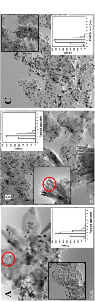
Transmission Electron Microscopy (TEM) studies of the samples were made by use of a JEOL 3010 high resolution transmission electron mi- croscope operating at 300 kV. Particle size of composite supported Pt catalysts were determined by measuring the diameters of no less than 900 randomly selected metal particles in at least ten micrographs of each sample taken from non-aggregated areas using the ImageJ software.
X-ray photoelectron spectroscopy (XPS) measurements were per- formed using an electron spectrometer manufactured by OMICRON Nanotechnology GmbH (Germany). MgKα (1253.6 eV) radiation was used as excitation source and data were acquired with 1 eV spectral resolution (30 eV pass energy). The powdered composite supports and catalysts were suspended in isopropanol or hexane and drops of this suspension were dried onto stainless steel sample plates. Spectra were processed with the CasaXPS package [59] by fitting the measured data with a combination of Gaussian-Lorentzian product peaks over a Shirley-type background, while quantitative evaluation of the data was performed with the XPSMultiQuant package [60,61] during which a homogeneous depth distribution was assumed for all components.
Chemical states were identified using the NIST database [62], the pub- lication [63] or other literature as indicated. Binding energies were referenced to the lowest binding energy contribution of the C 1s enve- lope, which was assigned to graphite-like (sp2-hybridized) carbon in the carbon backbone (284.4 eV).
2.4. Electrochemical characterization
A Biologic SP 150 potentiostat and a standard three-electrode elec- trochemical cell were used for the electrochemical measurements. The applied electrolyte was 0.5 M H2SO4 solution, which was prepared by
using Milli-Q water and concentrated H2SO4.
Glassy carbon (GC; d=0.3 cm) electrode with 0.0707 cm2 surface area was used as working electrode. Platinum wire was used as counter electrode and a hydrogen electrode as reference electrode. All potentials are given on RHE scale. The details of the working electrode prepara- tion, the catalyst ink composition and electrocatalytic measurements were described in Refs. [45,48]. The Pt loading of the electrodes was 10 μg cm−2. Taking into account the possible inhomogeneity of the sam- ples, usually at least three independent electrochemical measurements were carried out.
Electrocatalytic performance of the 20 wt.% Pt/Ti0.8Mo0.2O2-C electrocatalysts was studied by cyclic voltammetry and COads-stripping voltammetry measurements combined with stability test involving 500 polarization cycles and the second COads-stripping voltammetry mea- surement. In the long-term stability test, the samples were submitted to cyclic polarization at a 100 mV s−1 scan rate for 10,000 cycles between 50 and 1000 mV potential limits; these measurements took ca. 54 h.
The charges associated with hydrogen underpotential deposition, QoxHupd, were calculated using conventional baseline correction. From the oxidation charge of the monolayer hydrogen the electrochemically active Pt surface area (ECSAHupd) can be calculated using the Eq. 1 [64]:
ECSAHupd (cm2) =QoxHupd (μC) / 210 (μC/cm2),w (1) here ECSAHupd is the electrochemical surface area determined from the amount of underpotentially deposited hydrogen on the platinum sur- face; QoxHupd is the oxidation charge of underpotentially deposited hydrogen obtained from the CV experiment and 210 (μC/cm2) is the amount of charge required to oxidize monolayer hydrogen adsorbed on 1 cm2 of polycrystalline platinum surface.
Results concerning on the change of the electrochemically active Pt surface area upon the N-cycle stability test are presented as ECSAN (N:
500, 2,500, 5000 and 10,000) normalized to ECSA1 measured in the first cycle on the same sample. Another measure of the change of the elec- trochemically active Pt surface area is the ΔECSA value defined in Eq. 2 [57]:
ΔECSAN={1-(ECSAN/ECSA1)}×100 % (2) After every stability test the electrolyte was changed to fresh one to avoid the re-deposition of the dissolved metals. Electrochemical per- formance of the Pt/Ti0.8Mo0.2O2-C electrocatalysts was compared with that of 20 wt.% Pt/C (Quintech) commercial one.
3. Results and discussion
3.1. Influence of the phase composition and microstructure of the composites on the electrochemical performance of the related Pt catalysts.
Preliminary results
In the Introduction we emphasized the importance of the exclusive formation of the rutile mixed oxide phase on the carbon and the good incorporation of Mo in order to get stable electrocatalysts. Without adaption of the synthesis procedure to the surface chemical features of Table 1
Nominal composition and preparation details of the carbon-containing (C =BP, F-BP and Vulcan) and GO derived composites with the different Ti0.8Mo0.2O2/C ratios.
N◦ Samples nominal composition a TiO2 sol Suspension of carbon Mo prec.b(g)
H2O (ml) HNO3 (ml) Ti prec.b (ml) C (g) H2O (ml) HNO3c (ml)
25C 75Ti0.8Mo0.2O2-25C 21 2.35 2.05 0.25 10 – 0.2989
50C 50Ti0.8Mo0.2O2-50C 14 1.55 1.36 0.50 12.5 0.39 0.1993
75C 25Ti0.8Mo0.2O2-75C 7 0.78 0.68 0.75 15 0.78 0.0997
25GO 75Ti0.8Mo0.2O2-25C 21 1.11 0.79 0.17d – – 0.1172
aExpected composition of composites with different Ti0.8Mo0.2O2/C mass ratio.
b Ti and Mo precursor compounds: (Ti(O-i-Pr)4 and (NH4)6Mo7O24 ×4H2O).
ccc. HNO3 (65 %, Molar Chemicals, a.r.).
dGO in a suspension of 0.95 wt.%, pH adjusted to 9 with NaOH solution.
the carbon material, often a mixture of rutile and anatase was formed, sometimes along with excessive segregation of Mo-oxides. In this section XRD and electrochemical results obtained on catalysts with multiple oxide phases will be discussed in order to justify our efforts for opti- mization of the composite preparation.
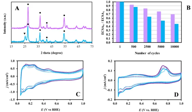
Fig. 2A shows the XRD patterns obtained on Ti0.8Mo0.2O2-C com- posite materials prepared using HNO3 and glucose functionalized BP carbon, with (25F-BP) and without previous treatment in nitrogen at 1000 ◦C (25F*-BP). As can be seen in Fig. 2A in the case of the 25F-BP sample only the reflections of the TiO2-rutile crystallites were observed, but in the 25F*-BP sample the mixture of the TiO2-rutile and anatase phases was detected.
According to our previous studies [57], the percentage of the surface oxygen functional groups (FGs) of the HNO3-glucose functionalized BP carbon materials and the BET surface area of the corresponding com- posites were quite similar, irrespectively to the pre-treatment of carbon at 1000 ◦C (FG =19.5 and 22 % and SBET =135 and 147 m2/g for the 25F*-BP and 25F-BP, respectively). However, the ratio between the surface oxygen FGs decomposed below and above 500 ◦C was different;
pre-treatment of carbon at 1000 ◦C resulted in higher content of the FGs decomposed above 500 ◦C [57]. It has been demonstrated in our pre- vious studies [48,51] that preliminary formation of the rutile-TiO2 phase in the presence of carbon at room temperature (RT) is prerequisite for complete dopant (Mo, W) incorporation into the TiO2 lattice upon high-temperature treatment. In order to facilitate the formation of rutile nuclei, the duration of the RT aging of the Ti-sol in the presence of carbon and the acidity of the synthesis mixture were optimized. How- ever, when using composite materials prepared with various function- alized carbons, one more variable should be considered: despite using the same preparation procedure, it is likely that various surface oxygen FGs of different character (hydroxyl, carboxylic, lactone, ether groups, etc. [57]) have different influence on the deposition of TiO2 nuclei on the carbon backbone during the first preparation step, resulting in exclusive formation of TiO2-rutile or mixture the rutile and anatase
phases.
According to the literature [65–67] and our recent study [57], the mass losses in the low temperature range from 200 to 500 ◦C on the TGA curves of the samples treated with (HNO3 +glucose) can be related (i) to elimination of hydroxyl and carboxyl groups (227 ◦C and 273 ◦C, respectively) as well as (ii) to the decomposition of the stronger chem- ical bonds in glucose (337 ◦C). Thus, it can be concluded that the presence of higher content of the FGs decomposed below 500 ◦C has negative influence on the exclusive formation of TiO2-rutile.
Moreover, we demonstrated [57] that the major part of the FGs (65
%) of carbon functionalized without pre-treatment at 1000 ◦C can be eliminated upon treatment in N2 at 500 ◦C for 1 h. Since for incorpo- ration of Mo into rutile lattice treatment at 600 ◦C is needed [48,51], the presence of higher content of FGs, which decomposed above 500 ◦C, can be beneficial for the increase of the composite stability. In this respect, the final dispersion of deposited metal oxides and resistance to sintering are more negatively affected by the presence of the less stable FGs.
As derived from the CV-s in Fig. 2.C, during the 500-cycle stability tests very small performance loss was observed on both catalysts (7,0 % and 12.6 % on the Pt/25F-BP and Pt/25F*-BP, respectively, see also Fig. 2B). Electrochemically active Pt surface area calculated from the CVs of fresh catalysts was 60.9 m2/gPt and 58.9 m2/gPt for the Pt/25F-BP and Pt/25F*-BP, respectively. Moreover, very similar behaviour in the COads stripping measurements (Fig. 2D) was observed on both electro- catalysts. However, according to the results of the 10,000-cycle long- term stability test (see Fig. 2B) pronounced difference was observed between the two catalysts: the ΔECSA values calculated for the Pt/25F- BP and Pt/25F*-BP catalysts were 30.5 and 54.2 %, respectively. These results clearly demonstrate that the presence of the mixed oxide in the form of different crystalline phases in the composite materials nega- tively affects the long-term stability of the corresponding catalyst.
In the next set of experiments Ti0.8Mo0.2O2-C composite supported catalysts with high mixed oxide content prepared using unmodified (25V) and HNO3-glucose-functionalized Vulcan (25F-V) were compared
Fig. 2.(A) XRD patterns of functionalized BP-containing Ti0.8Mo0.2O2-C composites (25F-BP ( ) and 25F*-BP ( )) after HTT; ●- rutile, ▾- anatase. (B) Comparison of the electrochemically active Pt surface measured after N cycles normalized to ECSA measured in the 1st cycle (ECSAN/ECSA1) of the Pt/25F-BP ( ) and Pt/25F*-BP ( ) catalysts as a function of the number of cycles (N). (C) CVs and (D) COads stripping voltammograms of the Pt/25F-BP and Pt/25F*-BP catalysts recorded before (solid line) and after 500 cycles (dotted line) of the stability test. Obtained in 0.5 M H2SO4 at 100 mV/s (C) and 10 mV/s (D), T=25 ◦C. Preparation details of the functionalization of BP carbon are given in Ref. [55].
(Fig. 3).
In our recent study it has been demonstrated [57] that functionali- zation of carbon, resulting in a more uniform mixed oxide coating, un- fortunately leads to a marked decrease in the specific surface area (SSA) and total pore volume of the composite support materials; in addition, the higher the oxide content, the more pronounced the decrease in surface area. Thus, the lowest value of the SBET =147 m2/g was obtained for the functionalized F-BP-based composite with 75 wt.% of mixed oxide (see 25F-BP in Table 2). Unfortunately, the use of Vulcan as a carbon source in the preparation of composites with high mixed oxide content (see sample 25V in Table 2) results in materials with surface area below the recommended value for electrocatalyst support (100 m2/g). Moreover, our results showed that a decrease of the surface area of the composite largely hinders the incorporation of Mo into the TiO2
lattice. According to XRD pattern of the 25V composite studied after HTT the reflections of the TiO2-rutile were found together with minor
amount of the MoO2 crystalline phase (see Fig. 3A). However, a mixture of the TiO2-rutile with relatively big amount of anatase phases was detected in the 25F-V sample (see Fig. 3A). It is necessary to mention that according to our previous results the TiO2-anatase phase is not suitable for Mo doping with our technique [48,57]. Consequently, the presence of certain amount of unincorporated amorphous MoO2 located on the surface of the composite support can be expected.
Despite the low surface area of the composite materials high ECSA calculated from CVs (Fig. 3C) and relatively small ΔECSA in the 500- cycle stability test were obtained for both catalysts (ECSA =81.3 m2/ gPt and 88.4 m2/gPt; ΔECSA =9.0 and 12.2 % for the Pt/25V and Pt/
25F-V, respectively).
The CO electrooxidation (the so-called “pre-peak”) started on both catalysts at ca. 50 mV (see Fig. 3D). As shown in Fig. 3D the main dif- ference observed on these two catalysts was the intensity of the “pre- peak” area; quite pronounced “pre-peak” area was characteristic for the Fig. 3.(A) XRD patterns of Vulcan-containing Ti0.8Mo0.2O2-C composites (25V ( ) and 25F-V ( )) after HTT; ●- rutile, ▾- anatase, ◼- MoO2. (B) Comparison of the electrochemically active Pt surface area measured after N cycles normalized to ECSA measured in the 1st cycle (ECSAN/ECSA1) of the Pt/25V ( ) and Pt/25F-V ( ) catalysts as a function of the number of cycles (N). (C) CVs and (D) COads stripping voltammograms of the Pt/25V and Pt/25F-V catalysts recorded before (solid line) and after 500 cycles (dotted line) of the stability test. Obtained in 0.5 M H2SO4 at 100 mV/s (C) and 10 mV/s (D), T=25 ◦C.
Table 2
Characterization of the Ti0.8Mo0.2O2-C composites and the related Pt catalysts by TEM, XRD and nitrogen adsorption measurements.
Sample Nominal composition C type a SBET, m2/g b Pore volume, cm3/g b Pt size, nm (TEM) Lattice parameters, Å c Mo subst., % Pt, % (XRD) 25BP 75Ti0.8Mo0.2O2-25C BP 248 d 0.51 2.9 ±0.8 d a=4.630, c=2.940 18 –
50BP 50Ti0.8Mo0.2O2-50C BP 411 1.02 2.3 ±0.5 a=4.630, c=2.940 18 –
75BP 25Ti0.8Mo0.2O2-75C BP 1120 d 2.01 2.7 ±0.7 d a=4.630, c=2.940 18 – 25F-BP 75Ti0.8Mo0.2O2-25C F-BP 147 d 0.39 2.5 ±0.6 d a=4.630, c=2.940 18 –
50F-BP 50Ti0.8Mo0.2O2-50C F-BP 455 0.81 3.1 ±0.7 a=4.630, c=2.940 18 –
75F-BP 25Ti0.8Mo0.2O2-75C F-BP 726 d 1.32 2.8 ±0.7 d a=4.630, c=2.940 18 –
25V 75Ti0.8Mo0.2O2-25C V 47 0.28 2.0 ±0.6 a=4.630, c=2.940 18 –
50V 50Ti0.8Mo0.2O2-50C V 108 0.38 2.4 ±0.6 a=4.630, c=2.940 18 –
75V 25Ti0.8Mo0.2O2-75C V 175 0.48 2.0 ±0.6 a=4.630, c=2.940 18 –
25GO 75Ti0.8Mo0.2O2-25C GO 130 0.39 2.4 ±0.9 a=4.640, c=2.935 23 –
Pt/25GO 20 Pt/75Ti0.8Mo0.2O2-25C GO – – 2.4 ±0.9 a=4.640, c=2.935 23 17.1
Pt/25BP 20 Pt/75Ti0.8Mo0.2O2-25C BP – – 2.9 ±0.8 a=4.630, c=2.940 18 21.4
aBP: Black Pearls 2000, V: Vulcan; GO: Graphite Oxide derived carbon; F-BP: BP carbon pre-treated at 1000 ◦C in nitrogen for 3 h before functionalization, then functionalized with HNO3 and glucose.
b Specific surface area and total pore volume of the composite support materials determined by nitrogen adsorption measurements.
cLattice parameters of the rutile phase obtained after HTT; Pure rutile TiO2: a=4.593 Å, c=2.959 Å.
dFrom Ref. [57].
Pt/25F-V catalyst. We demonstrated earlier [45] that only CO adsorbed on specific Pt sites, where Pt and Mo atoms are in atomic closeness, can be oxidised below 400 mV potential. Thus, taking into account the high intensity of the “pre-peak” area it can be assumed that the number of MoOx particles in the close vicinity of the Pt in the Pt/25F-V catalyst may be higher. It is necessary to mention that the intensity of Mo redox peak pair observed on this sample was also higher comparing to the Pt/25V catalyst as shown in Fig. 3C.
Nevertheless, the stability of these catalysts is among the worst compared to the other ones studied in this work. Significant degradation was observed on both catalysts after 10,000 polarization cycles: ΔECSA
=43.6 and 46.5 % for the Pt/25V and Pt/25F-V catalysts, respectively.
Apart from the complicated phase composition, the fast degradation seems also to be connected to the low SSA of the Vulcan-containing composite. This issue will be further discussed at the end of the paper.
These results demonstrate that not only the phase composition, but also the surface area of the catalyst support, especially that of its mixed oxide part, plays an important role in the development of promising electrocatalysts.
3.2. Characterization of the Ti0.8Mo0.2O2-C composites and the related Pt catalysts by XRD. Optimization of the preparation procedure
As was mentioned above the main goal of this study was to use Vulcan, BP and GO as carbon materials to develop the synthesis of a composite with different mixed oxide/carbon ratio and rutile structure of Mo-doped TiO2 to create highly efficient and stabile electrocatalysts with an optimal ratio between Ti0.8Mo0.2O2 and carbon.
In order to adapt the composite preparation method for GO, we had to overcome the difficulty that strong acidic media is necessary for the formation of the rutile nuclei (consequently to Mo incorporation), whereas mild basic media is necessary for the delamination of GO.
During the preparation we choose the strong acidic media (0.69 M HNO3) to form rutile nuclei and we added the delaminated solution of GO (pH adjusted to 9 with NaOH) suddenly to the reaction mixture by use of vigorous stirring. The original pH was then restored with cc.
HNO3 (see Fig. 1B in Experimental part). According to the XRD pattern of the samples obtained after the drying step at 85 ◦C and before HTT this procedure resulted in rutile nuclei beside the amorphous part (see Fig. 4A). Subjecting these samples to HTT, further crystallization occurred. After HTT the XRD patterns of the 25GO samples showed the presence of rutile phase with trace of the MoO2 phase (Fig. 4A).
Literature dealing with rutile-based mixed oxides indicates that W- or Mo-incorporation results in a characteristic distortion of the rutile- TiO2 cell [68] and the change in the cell parameters measured by X-ray diffraction can be used for characterization of the amount of incorpo- rated doping cations. According to this, changes of lattice parameters presented in Table 2 (a =4.640, c=2.935 Å, while pure rutile TiO2 structure has a=4.593 Å, c=2.959 Å) indicated 23 % of Mo substitution
for the mixed oxide – GO composite. It should be noted that the degree of Mo incorporation (calculated Mosubst = 23 %) was higher than the nominal Mo content (nominal Mosubst =20 %) only in case of the GO derived composite materials. The application of the additional washing step with diluted nitric acid for NaNO3 removal before the introduction of the Mo precursor compound was a distinctive feature of the synthesis of GO-based composite materials. As a result, certain part of TiO2-rutile nuclei, deposited onto the carbon backbone may have been removed.
Consequently, the real Ti/Mo ratio could be smaller than the nominal one. According to our previous studies upon the preparation of the composite support containing mixed oxide with Ti/Mo ratio of 80/20 and 70/30 the degree of Mo incorporated into the unit cell was 21 and 25 %, respectively [48]; based on above results, the actual Ti/Mo ratio during the GO-based synthesis could be between 80/20 and 70/30.
Broad reflections at 2 theta values of 39.6, 47.4, 67.1◦, arise from the (111), (200), and (220) planes of the fcc structure of platinum, respec- tively [69]. The broad diffraction peaks indicate the presence of nano- dispersed Pt crystallites in the Pt/25GO catalyst (Fig. 4A).
As shown in Fig. 4B only the reflections of the TiO2-rutile crystallites were observed in the XRD pattern of the 25V composite studied before HTT; no reflections characteristic to Mo oxides were found. However, after HTT the reflections of the TiO2-rutile and very small amount of MoO2 crystalline phase were detected (see Fig. 4B). The characteristic distortion in the lattice parameters of the rutile phase obtained after HTT on the 25V composite (a=4.630 Å, c= 2.940 Å, see Table 2) confirmed the incorporation of Mo into TiO2-rutile lattice with Mosubst = 18 %. It should be noted that the relatively small surface area of Vulcan can be a reason of the presence of some amount of unincorporated MoO2
crystalline phase (especially in the case of the V-based composites with high oxide content (25V)).
Therefore, in the preparation of Vulcan-containing composites, one more step was added: after introduction of the Mo precursor compound the synthesis mixture was treated at 65 ◦C under continuous stirring for additional 2 h; then, as usual, the solvent was evaporated overnight at 65 ◦C. Our experience shows that the addition of this new step results in pronounced decrease of the reflections characteristic to the crystalline MoO2 phase. As shown in Fig. 1 (route A), the preparation of all com- posites presented in this study was done with the inclusion of this additional treatment.
As shown in Fig. 4B the deposition of platinum resulted again in the appearance of the broad lines characteristic to the reflections of very small Pt crystallites.
The influence of the type of carbonaceous material on the structure and composition of the 25C (C=BP, V and GO) composite supported Pt catalysts was demonstrated in Fig. 5A. As shown in Fig. 5A taking into account the peculiarities of various carbonaceous materials optimal synthesis method was developed for the preparation of the 25C com- posites with high mixed oxide content and total Mo incorporation into the rutile-TiO2 lattice; no reflections characteristic to unincorporated
Fig. 4. XRD patterns of the GO- (A) and Vulcan-containing Ti0.8Mo0.2O2-C composites (B) with low carbon content (25C) before and after HTT as well as after Pt loading. ●- Rutile, ◼- MoO2.
MoOx oxides were found. Moreover, in all Pt/25C catalysts the platinum is present in nanodispersed form. As seen from Fig. 5A, using an opti- mized synthesis, it was possible to prepare catalysts with very similar phase composition.
Furthermore, Pt loading has no influence on the lattice parameters and degree of Mo incorporation characteristic for these composite ma- terials (cf. 25BP and Pt/25BP, 25GO and Pt/25GO in Table 2). Platinum content of Pt/25B and Pt/25GO estimated by XRD analysis was in a good agreement with the 20 wt.% used in the catalysts preparation.
The influence of the mixed oxide/carbon ratios (Ti0.8Mo0.2O2/C = 75/25, 50/50 and 25/75) in the composite supports containing BP, F-BP and Vulcan on the structure and phase composition of Pt catalysts is shown in Table 2 and Fig. 5B–D. In our previous study [57] the method of the preparation of BP- and functionalized F-BP-based composite supports for Pt electrocatalysts with 75/25 and 25/75 oxide/carbon mass ratio was already demonstrated. It has been emphasized above (see Experimental part), that the synthesis of composites with high carbon content (50C and 75C) of Mo-doped TiO2 rutile structure differed from synthesis of composite materials with low carbon content (25C) in the duration and temperature of the aging step. In addition, it was necessary to compensate the whole acidity of the synthesis mixture by one more addition step of cc. HNO3 before starting the aging procedure. Fig. 5B–D show, that despite of all difficulties, these problems were successfully resolved.
As seen from Fig. 5B–D and Table 2 in all BP, F-BP and Vulcan- containing samples (i) only the reflections of the TiO2-rutile crystal- lites were present; (ii) no reflections characteristic to MoO2 or MoO3
oxide phase were found; (iii) the platinum was present in highly dispersed form; and (iv) no changes in the lattice parameters connected to the degree of Mo incorporation were observed (a=4.630 Å, c=2.940 Å and Mosubst =18 %).
It is necessary to mention that the less sharp diffraction peaks (see Fig. 5B–D) observed in the XRD pattern of the samples with low mixed oxide content in the carbon matrix (75C) may be attributed to the small
amount of the mixed oxide in the composite material.
3.3. Microstructure of the composite supported Pt electrocatalysts 3.3.1. N2 adsorption measurements
As was mentioned above one of the main requirements for the promising electrocatalyst supports is to have a SSA not less than 100 m2/ g [2]. As can be seen from data in Table 2 (and Table S1 in the Sup- plementary Materials), the SSA of Ti0.8Mo0.2O2-C composites was basi- cally determined by two main factors (i) the mixed oxide/carbonaceous material ratio and (ii) the nature or SSA of the parent carbonaceous material. Upon decreasing the content of the carbonaceous material in the BP, functionalized F-BP and Vulcan-containing composites the SSA also decreased gradually; the lowest SSA values were obtained for the composites with Ti0.8Mo0.2O2/C =75/25 ratio (see 25C (C=BP, F-BP and V) samples in Table 2).
When SSA of the parent electrically conductive carbon blacks was large enough, such as for BP (SBET=1635 m2/g according to Ref. [16]
and 1485 m2/g according to Ref. [70]), the presence of even 25 wt.% of carbon in the Ti0.8Mo0.2O2-C composite materials was sufficient to get the expected SSA (see Table 2). In the case of Vulcan with much smaller SSA (SBET=245 m2/g according to Ref. [16] and 232 m2/g according to Ref. [70]), with decreasing carbon content in composites, the changes in SSA values were as follows: 175 m2/g (75V) >108 m2/g (50V) >47 m2/g (25V). However, although the 25V composite has the lowest SSA, the surface area of this composite is still higher than that can be achieved for carbon-free mixed oxides.
Electrically conductive carbon blacks, consisting of nearly spherical primary particles fused together in aggregates, like BP have usually high SSA, but contain a significant volume of micropores, too [16]. However, it should be noted that one of the important requirements for the implementation in PEM fuel cells is an appropriate porosity of the support material in order to facilitate mass transfer of liquid fuels or oxygen gas and to minimize water flooding in electrodes [2]; in this Fig. 5. XRD patterns of Pt/Ti0.8Mo0.2O2-C catalysts: (A) Influence of the type of carbonaceous material used on the structure of the 25C (C=BP, V and GO) composite supported Pt catalysts. Influence of the Ti0.8Mo0.2O2/C ratios (Ti0.8Mo0.2O2/C =75/25, 50/50 and 25/75) in the composite supports containing BP (B), F-BP (C) and Vulcan (D) on the structure of Pt catalysts. ●- Rutile.
regard, the presence of micropores in BP carbon has negative influence on the performance of the electrocatalysts.
Both total pore volumes (Table 2) and micropore volumes (Table S1 in the Supplementary Materials) decreased parallel with the decrease of the carbon content of the Ti0.8Mo0.2O2-C composites. This trend was valid for composites containing Vulcan, unmodified and functionalized BP carbon and was in good agreement with literature results obtained on TiO2-coated activated carbon materials [71,72]. In this series of exper- iments (see Table S1 in the Supplementary Materials) the 25V composite has the smallest total pore volume (0.14 cm3/g) and practically no mi- cropores (<0.01 cm3/g).
A comparison of samples with the same mixed oxide/carbon ratio (cf. 25F-BP and 25BP; 75F-BP and 75BP samples in Table 2) showed that both SSA and the pore volume were smaller on the functionalized F-BP- based composite in comparison to the unmodified BP-based ones. This may also indicate that a more uniform mixed oxide layer was formed on the functionalized carbon than on the unmodified one. Tentatively, it can be assumed that mixed oxide particles tend to block micropores of the carbonaceous material. Then a uniform coating would result in complete loss of the surface area within the pores for nitrogen adsorp- tion. On the contrary, if only a few large grains of the mixed oxide were formed, the measured surface area should even increase somewhat, corresponding to the additive contribution of the separated species.
The shape of the isotherms obtained by nitrogen adsorption mea- surements also significantly depended on both the nature of the carbo- naceous material and the mixed oxide/carbon ratio (see Fig. S1 in Supplementary Materials). Unmodified BP- and functionalized F-BP- based composites with 75 wt. % of carbonaceous content showed typical H1 type of hysteresis loop according the UPAC classification [73] (see Fig. S1 in the Supplementary Material). Upon increasing the mixed oxide content, the hysteresis loop became very narrow which indicates space amongst the aggregated particles rather than a well-defined cylindrical pore structure. The narrow hysteresis loop was also characteristic for all Vulcan-based samples. Contrary, isotherm of 25GO sample had a hys- teresis loop of a typical H3 shape (see Fig. S1 in Supplementary Mate- rials), which referred to the presence of aggregated flat particles and reflects the structure of the parent carbonaceous material, i.e. the graphene-oxide sheets of the delaminated GO.
In summary, all composite had a sufficiently large specific surface area to be used as a support for electrocatalysts in PEM fuel cells with the exception of the sample 25V as it has been mentioned in Chapter 3.1.
3.3.2. XPS investigations
Similarly to the phase composition, the general qualitative electron spectroscopic features of the composite materials and the related elec- trocatalysts were rather similar, irrespectively to the type of the carbon material or the mixed oxide/carbon ratio. The carbon content of all studied samples was predominantly graphitic (main C 1s peak at 284.4 eV binding energy). Only the graphite oxide-derived materials con- tained oxidized species in a somewhat larger amount (a small peak slightly above 286 eV arose from carbon atoms singly bound to oxygen, like in C–OH or in C–O–C in epoxide or lactone groups and another one around 288.5 eV appeared due to highly oxidized carbon species (carboxylic or anhydride functionalities [74,75]). This indicates that the steps applied during composite synthesis largely reduced even the graphite oxide. The narrow and sharp Ti 2p3/2 peak at 458.8 eV confirmed the exclusive presence of Ti4+in the composite materials. The Mo 3d spectra of all samples showed the characteristics of Mo in the mixed oxide – carbon composite material as described in our previous works [45,46]. Based on XRD and XPS results no Mo-carbide formation was observed in any of our Ti0.8Mo0.2O2 - C composite support materials due to the relatively low temperature of HTT compared to the commonly used carbide production methods [76]. The general appearance of the Mo 3d spectra were rather similar in all samples, regardless to the type of the carbonaceous material, the mixed oxide/carbon ratio or the Pt loading in the electrocatalysts (as a representative example, spectra for the mixed oxide-rich 25BP, 25V and 25GO composites are shown in Fig. S2 in Supplementary Materials). Shortly, the Mo 3d spin-orbit splitted doublet was in all cases slightly asymmetric towards the low binding energies; its main contribution arose from the Mo6+ionic state (Mo 3d5/2 peak around 232.5 eV [77]), which was accompanied by weaker (around 10–20 %) Mo5+(3d5/2 peak around 231 eV [77]) and Mo4+(leading peak around 230 eV [77,78]) contributions. The O 1s spectrum in all cases consisted of a strong leading peak slightly above 530 eV binding energy (arising from O ions bound to metal (Ti- or Mo) cations), which was accompanied by a tail region towards high binding energies containing contributions from hydroxyl groups on the mixed oxide and C–O–C groups in epoxide from the carbon backbone (around 531 eV) and hydroxyl and carboxyl groups on the carbon backbone along with adsorbed water (around 533 eV) [74,75]. The platinum content in all electrocatalyst was predominantly metallic (Pt 4f7/2 peak slightly above 71 eV binding energy).
In spite of the general similarity of the carbon, titanium, molybde- num or platinum chemical states in the studied samples, notable Table 3
Composition of the mixed oxide composite supports and the studied electrocatalysts from XPS measurements.
Sample Ti/Moa (at%/at%)
Ti +Mo +O)/C (wt%/wt%) Ptb (wt%)
XPS ICP XPS ICP
25BP 2.5/1 – 58.4/41.6 – –
50BP 2.9/1 – 46.2/53.8 – –
75BP 3.3/1 – 22.7/77.3 – –
25V 1.9/1 – 70.0/30.0 – –
25Vc 3.8/1 – 58.0/42.0 – –
25GO 1.6/1 – 60.1/39.9 – –
Pt/25BP 3.5/1 5.2/1 (5.0/1)d 58.0/42.0e 44.0 18.5 (22.2)d
Pt/50BP 3.8/1 4.7/1 40.3/59.7e 35.6 18.7
Pt/75BP 4.9/1 5.1/1 19.0/81.0e 22.0 16.2
Pt/25F-BP 3.6/1 5.1/1 70.0/30.0e 53.0 16.3
Pt/50F-BP 4.3/1 5.7/1 32.7/67.3e 39.1 17.7
Pt/75F-BP 5.2/1 6.0/1 20.0/80.0e 33.0 18.3
Pt/25V 3.8/1 5.2/1 61.9/38.1e 48.3 18.4
Pt/50V 3.6/1 5.0/1 37.2/62.8e 42.5 18.8
Pt/75V 4.1/1 5.7/1 19.1/80.9e 41.5 17.2
Pt/25GO 2.4/1 n.d. 54.8/45.2e 39.1 n.d.
aNominal Ti/Mo=4:1.
b The nominal Pt content: 20 wt.%.
c“Blank Pt-loading experiment”: all steps of Pt loading were performed without addition of Pt precursor.
dData in brackets were obtained by X-ray fluorescence (XRF) and energy dispersive X-ray spectroscopy (EDX).
eCalculated without the Pt content; n.d.=no data.